EP0747224A1 - Messsystem der Menge ausgestossener Tinte während des Druckens - Google Patents
Messsystem der Menge ausgestossener Tinte während des Druckens Download PDFInfo
- Publication number
- EP0747224A1 EP0747224A1 EP96303812A EP96303812A EP0747224A1 EP 0747224 A1 EP0747224 A1 EP 0747224A1 EP 96303812 A EP96303812 A EP 96303812A EP 96303812 A EP96303812 A EP 96303812A EP 0747224 A1 EP0747224 A1 EP 0747224A1
- Authority
- EP
- European Patent Office
- Prior art keywords
- ink
- discharged
- amount
- density
- discharging
- Prior art date
- Legal status (The legal status is an assumption and is not a legal conclusion. Google has not performed a legal analysis and makes no representation as to the accuracy of the status listed.)
- Granted
Links
- 238000007639 printing Methods 0.000 title claims description 67
- 238000007599 discharging Methods 0.000 claims abstract description 124
- 238000000034 method Methods 0.000 claims abstract description 124
- 238000012545 processing Methods 0.000 claims description 30
- 238000002835 absorbance Methods 0.000 claims description 27
- 238000005303 weighing Methods 0.000 claims description 10
- 238000002474 experimental method Methods 0.000 claims description 5
- 230000006870 function Effects 0.000 claims description 3
- 238000013213 extrapolation Methods 0.000 claims 1
- 239000011521 glass Substances 0.000 abstract description 18
- 239000000976 ink Substances 0.000 description 299
- 238000005259 measurement Methods 0.000 description 30
- 239000007788 liquid Substances 0.000 description 12
- 239000002250 absorbent Substances 0.000 description 9
- 239000012530 fluid Substances 0.000 description 8
- 238000010438 heat treatment Methods 0.000 description 7
- 238000012937 correction Methods 0.000 description 6
- 230000008569 process Effects 0.000 description 5
- 238000009835 boiling Methods 0.000 description 4
- 239000000463 material Substances 0.000 description 4
- 230000003287 optical effect Effects 0.000 description 4
- 239000007787 solid Substances 0.000 description 4
- 239000004372 Polyvinyl alcohol Substances 0.000 description 2
- 238000003705 background correction Methods 0.000 description 2
- 230000008859 change Effects 0.000 description 2
- 230000003247 decreasing effect Effects 0.000 description 2
- 230000000694 effects Effects 0.000 description 2
- 238000012986 modification Methods 0.000 description 2
- 230000004048 modification Effects 0.000 description 2
- 229920002451 polyvinyl alcohol Polymers 0.000 description 2
- 230000004043 responsiveness Effects 0.000 description 2
- 230000002745 absorbent Effects 0.000 description 1
- 238000004140 cleaning Methods 0.000 description 1
- 239000003086 colorant Substances 0.000 description 1
- 238000007796 conventional method Methods 0.000 description 1
- 230000007423 decrease Effects 0.000 description 1
- 238000009826 distribution Methods 0.000 description 1
- 238000001704 evaporation Methods 0.000 description 1
- 230000008020 evaporation Effects 0.000 description 1
- 238000007641 inkjet printing Methods 0.000 description 1
- 230000031700 light absorption Effects 0.000 description 1
- 238000005457 optimization Methods 0.000 description 1
- 238000005192 partition Methods 0.000 description 1
- 239000011295 pitch Substances 0.000 description 1
- 238000002360 preparation method Methods 0.000 description 1
- 238000011084 recovery Methods 0.000 description 1
- 230000004044 response Effects 0.000 description 1
- 239000000126 substance Substances 0.000 description 1
- 238000009834 vaporization Methods 0.000 description 1
- 230000008016 vaporization Effects 0.000 description 1
Images




Classifications
-
- B—PERFORMING OPERATIONS; TRANSPORTING
- B41—PRINTING; LINING MACHINES; TYPEWRITERS; STAMPS
- B41J—TYPEWRITERS; SELECTIVE PRINTING MECHANISMS, i.e. MECHANISMS PRINTING OTHERWISE THAN FROM A FORME; CORRECTION OF TYPOGRAPHICAL ERRORS
- B41J2/00—Typewriters or selective printing mechanisms characterised by the printing or marking process for which they are designed
- B41J2/005—Typewriters or selective printing mechanisms characterised by the printing or marking process for which they are designed characterised by bringing liquid or particles selectively into contact with a printing material
- B41J2/01—Ink jet
- B41J2/015—Ink jet characterised by the jet generation process
- B41J2/04—Ink jet characterised by the jet generation process generating single droplets or particles on demand
- B41J2/045—Ink jet characterised by the jet generation process generating single droplets or particles on demand by pressure, e.g. electromechanical transducers
- B41J2/04501—Control methods or devices therefor, e.g. driver circuits, control circuits
- B41J2/04598—Pre-pulse
-
- B—PERFORMING OPERATIONS; TRANSPORTING
- B41—PRINTING; LINING MACHINES; TYPEWRITERS; STAMPS
- B41J—TYPEWRITERS; SELECTIVE PRINTING MECHANISMS, i.e. MECHANISMS PRINTING OTHERWISE THAN FROM A FORME; CORRECTION OF TYPOGRAPHICAL ERRORS
- B41J2/00—Typewriters or selective printing mechanisms characterised by the printing or marking process for which they are designed
- B41J2/005—Typewriters or selective printing mechanisms characterised by the printing or marking process for which they are designed characterised by bringing liquid or particles selectively into contact with a printing material
- B41J2/01—Ink jet
- B41J2/015—Ink jet characterised by the jet generation process
- B41J2/04—Ink jet characterised by the jet generation process generating single droplets or particles on demand
- B41J2/045—Ink jet characterised by the jet generation process generating single droplets or particles on demand by pressure, e.g. electromechanical transducers
- B41J2/04501—Control methods or devices therefor, e.g. driver circuits, control circuits
- B41J2/04508—Control methods or devices therefor, e.g. driver circuits, control circuits aiming at correcting other parameters
-
- B—PERFORMING OPERATIONS; TRANSPORTING
- B41—PRINTING; LINING MACHINES; TYPEWRITERS; STAMPS
- B41J—TYPEWRITERS; SELECTIVE PRINTING MECHANISMS, i.e. MECHANISMS PRINTING OTHERWISE THAN FROM A FORME; CORRECTION OF TYPOGRAPHICAL ERRORS
- B41J2/00—Typewriters or selective printing mechanisms characterised by the printing or marking process for which they are designed
- B41J2/005—Typewriters or selective printing mechanisms characterised by the printing or marking process for which they are designed characterised by bringing liquid or particles selectively into contact with a printing material
- B41J2/01—Ink jet
- B41J2/015—Ink jet characterised by the jet generation process
- B41J2/04—Ink jet characterised by the jet generation process generating single droplets or particles on demand
- B41J2/045—Ink jet characterised by the jet generation process generating single droplets or particles on demand by pressure, e.g. electromechanical transducers
- B41J2/04501—Control methods or devices therefor, e.g. driver circuits, control circuits
- B41J2/04558—Control methods or devices therefor, e.g. driver circuits, control circuits detecting presence or properties of a dot on paper
-
- B—PERFORMING OPERATIONS; TRANSPORTING
- B41—PRINTING; LINING MACHINES; TYPEWRITERS; STAMPS
- B41J—TYPEWRITERS; SELECTIVE PRINTING MECHANISMS, i.e. MECHANISMS PRINTING OTHERWISE THAN FROM A FORME; CORRECTION OF TYPOGRAPHICAL ERRORS
- B41J2/00—Typewriters or selective printing mechanisms characterised by the printing or marking process for which they are designed
- B41J2/005—Typewriters or selective printing mechanisms characterised by the printing or marking process for which they are designed characterised by bringing liquid or particles selectively into contact with a printing material
- B41J2/01—Ink jet
- B41J2/015—Ink jet characterised by the jet generation process
- B41J2/04—Ink jet characterised by the jet generation process generating single droplets or particles on demand
- B41J2/045—Ink jet characterised by the jet generation process generating single droplets or particles on demand by pressure, e.g. electromechanical transducers
- B41J2/04501—Control methods or devices therefor, e.g. driver circuits, control circuits
- B41J2/0458—Control methods or devices therefor, e.g. driver circuits, control circuits controlling heads based on heating elements forming bubbles
-
- B—PERFORMING OPERATIONS; TRANSPORTING
- B41—PRINTING; LINING MACHINES; TYPEWRITERS; STAMPS
- B41J—TYPEWRITERS; SELECTIVE PRINTING MECHANISMS, i.e. MECHANISMS PRINTING OTHERWISE THAN FROM A FORME; CORRECTION OF TYPOGRAPHICAL ERRORS
- B41J2/00—Typewriters or selective printing mechanisms characterised by the printing or marking process for which they are designed
- B41J2/005—Typewriters or selective printing mechanisms characterised by the printing or marking process for which they are designed characterised by bringing liquid or particles selectively into contact with a printing material
- B41J2/01—Ink jet
- B41J2/015—Ink jet characterised by the jet generation process
- B41J2/04—Ink jet characterised by the jet generation process generating single droplets or particles on demand
- B41J2/045—Ink jet characterised by the jet generation process generating single droplets or particles on demand by pressure, e.g. electromechanical transducers
- B41J2/04501—Control methods or devices therefor, e.g. driver circuits, control circuits
- B41J2/04588—Control methods or devices therefor, e.g. driver circuits, control circuits using a specific waveform
-
- B—PERFORMING OPERATIONS; TRANSPORTING
- B41—PRINTING; LINING MACHINES; TYPEWRITERS; STAMPS
- B41J—TYPEWRITERS; SELECTIVE PRINTING MECHANISMS, i.e. MECHANISMS PRINTING OTHERWISE THAN FROM A FORME; CORRECTION OF TYPOGRAPHICAL ERRORS
- B41J2/00—Typewriters or selective printing mechanisms characterised by the printing or marking process for which they are designed
- B41J2/005—Typewriters or selective printing mechanisms characterised by the printing or marking process for which they are designed characterised by bringing liquid or particles selectively into contact with a printing material
- B41J2/01—Ink jet
- B41J2/015—Ink jet characterised by the jet generation process
- B41J2/04—Ink jet characterised by the jet generation process generating single droplets or particles on demand
- B41J2/045—Ink jet characterised by the jet generation process generating single droplets or particles on demand by pressure, e.g. electromechanical transducers
- B41J2/04501—Control methods or devices therefor, e.g. driver circuits, control circuits
- B41J2/04591—Width of the driving signal being adjusted
-
- B—PERFORMING OPERATIONS; TRANSPORTING
- B41—PRINTING; LINING MACHINES; TYPEWRITERS; STAMPS
- B41J—TYPEWRITERS; SELECTIVE PRINTING MECHANISMS, i.e. MECHANISMS PRINTING OTHERWISE THAN FROM A FORME; CORRECTION OF TYPOGRAPHICAL ERRORS
- B41J2/00—Typewriters or selective printing mechanisms characterised by the printing or marking process for which they are designed
- B41J2/005—Typewriters or selective printing mechanisms characterised by the printing or marking process for which they are designed characterised by bringing liquid or particles selectively into contact with a printing material
- B41J2/01—Ink jet
- B41J2/21—Ink jet for multi-colour printing
- B41J2/2121—Ink jet for multi-colour printing characterised by dot size, e.g. combinations of printed dots of different diameter
- B41J2/2128—Ink jet for multi-colour printing characterised by dot size, e.g. combinations of printed dots of different diameter by means of energy modulation
-
- B—PERFORMING OPERATIONS; TRANSPORTING
- B41—PRINTING; LINING MACHINES; TYPEWRITERS; STAMPS
- B41J—TYPEWRITERS; SELECTIVE PRINTING MECHANISMS, i.e. MECHANISMS PRINTING OTHERWISE THAN FROM A FORME; CORRECTION OF TYPOGRAPHICAL ERRORS
- B41J29/00—Details of, or accessories for, typewriters or selective printing mechanisms not otherwise provided for
- B41J29/38—Drives, motors, controls or automatic cut-off devices for the entire printing mechanism
- B41J29/393—Devices for controlling or analysing the entire machine ; Controlling or analysing mechanical parameters involving printing of test patterns
Definitions
- a printing apparatus such as an ink-jet printer, which has a head consisting of a plurality of fine nozzles
- ink is discharged at a fixed interval for a predetermined time period, and the amount (weight) of used ink in the time period is measured by a chemical balance or the like (care must be used to minimize vaporization of ink during performing this operation). Thereafter, by dividing the amount of ink used by the number of discharging operation performed, an average amount of ink droplet in each discharging operation can be obtained.
- This method uses the relationship between concentration of solution and light absorption, which is known as Lambert-Beer's law. More specifically, solution having a certain concentration is poured in a container having a fixed depth, and light having intensity I0 is incidented on the container from one side, then intensity I of the light transmitted through the solution in the container is measured. Since a part of the incidented light is absorbed in the solution in the container, its intensity is lowered while passing the solution. It is known that how the intensity is lowered proportional to the concentration of the solution.
- the concentration of the solution including ink is determined. Then, the amount of ink mixed in the solution can be found by taking the amount of the pure solution into consideration. Then the obtained amount of ink is divided by the number of discharging operations, thereby finding an average amount of ink discharged in each discharging operation.
- the present invention has been made in consideration of the above situation, and has as its object to provide a method and apparatus capable of measuring the amount of ink discharged from a nozzle instantaneously.
- the method comprising: a density measuring step of measuring the density of an ink dot formed by an ink discharged from the printhead on a predetermined medium; and a determining step of determining the amount of ink discharged on the basis of the density of the ink dot measured at the density measuring step.
- the method comprising: a preliminary measuring step of measuring the amount of ink discharged from each of a plurality of ink-discharging nozzles of the printhead in a single discharging operation under a predetermined condition in advance; a first density measuring step of measuring densitys of ink dots made of ink discharged from at least two different ink-discharging nozzles which discharge different amounts of ink from each other out of the plurality of ink-discharging nozzles onto a predetermined medium under the predetermined condition; a calibration line generating step of generating a calibration line representing correlation between the amount of ink discharged in a single discharging operation and a density of an ink dot on the basis of data on the densitys of the ink dots, measured at the first density measuring step, formed with the ink discharged from the at least two ink-discharging nozzles and data on the amount of ink, measured at the preliminary measuring step, discharged
- the apparatus comprising: density determination means for determining a density of an ink dot formed by an ink discharged from the ink-jet type printhead on a receiving medium for receiving the discharged ink; memory means for storing a calibration line representing correlation between the amount of ink discharged and a density of an ink dot formed by the discharged ink on the receiving medium in a single discharging operation; and operation means for finding the amount of the discharged ink on the basis of the density of the ink dot determined by the density determining means and the calibration line.
- the method comprising: a density measuring step of measuring the density of an ink dot formed by an ink discharged from the printhead on a receiving medium for receiving the discharged ink; and a determining step of determining the amount of ink discharged on the basis of the density of the ink dot measured at the density measuring step.
- the method comprising: a preliminary measuring step of measuring the amount of ink discharged from each of a plurality of ink-discharging nozzles of the printhead in a single discharging operation under a predetermined condition in advance; a first density measuring step of measuring densitys of ink dots made of ink discharged from at least two different ink-discharging nozzles which discharge different amounts of ink from each other out of the plurality of ink-discharging nozzles onto a receiving medium for receiving ink under the predetermined condition; a calibration line generating step of generating a calibration line representing correlation between the amount of ink discharged in a single discharging operation and a density of an ink dot on the basis of data on the densitys of the ink dots, measured at the first density measuring step, formed with the ink discharged from the at least two ink-discharging nozzles and data on the amount of ink,
- the method comprising: a density measuring step of measuring the density of a line of a line pattern formed with an ink discharged from the printhead on a predetermined medium; and a determining step of determining an amount of ink discharged on the basis of the density of the line of the line pattern measured at the density measuring step.
- the apparatus comprising: receiving means for receiving an ink discharged from the printhead; density determining means for determining the density of a line of a line pattern formed with the discharged ink on the receiving means; memory means for storing a calibration line representing correlation between the amount of ink discharged and the density of an ink dot formed by the discharged ink on the receiving means in a single discharging operation; and operation means for finding an amount of the discharged ink on the basis of the density of the line of the line pattern determined by the density determining means and the calibration line.
- ink discharged from each nozzle in a single discharging operation is uniformly absorbed by the ink-absorbent layer 12 and forms a round-shaped dot.
- the material of the ink-absorbent layer 12 a material which is as transparent and colorless as possible (i.e., which do not absorb light) is preferred.
- an image of the focused dot is inputted by the color CCD camera 5 to the image processing unit 1.
- a single color image can be decomposed into images of red (R), green (G) and blue (B) which are the three primary colors of light of optics, to form three monochromatic images, namely, a monochromatic image representing luminance level of light in the red (R) wavelength range, a monochromatic image representing luminance level of light in the green (G) wavelength range, and a monochromatic image representing luminance level of light in the blue (B) wavelength range.
- R red
- G green
- B blue
- These monochromatic images are formed with minimal pixel units to which the image processing unit 1 can resolve, and each minimal pixel can express luminance level in 256 tones, between 0 and 255 tone, in accordance with the intensity of the transmitted light through each pixel.
- a band-pass filter which selectively transmits light in the blue wavelength range is provided over a dot printed with red ink, and the luminance level of the transmitted light is measured in the monochromatic image which shows luminance levels of light in the blue wavelength range.
- the luminance level of the red dot in the blue monochromatic image since the overlapping wavelength range between the red wavelength range and the green wavelength range is wider than the overlapping wavelength range between the red wavelength range and the blue wavelength range.
- a dot pattern to be measured shown in Fig. 2 are printed with blue ink on the glass plate 10. Therefore, luminance levels of the dots are measured in the red monochromatic image because of the aforesaid reason.
- an image of a pixel subjected to measurement inputted as described above is marked with a fixed sized frame (called “window”, hereinafter) as shown in Fig. 3.
- window a fixed sized frame
- a window whose size is large enough to surely includes the entire dot subjected to measurement (including its surrounding) is used to specify an area, then all the luminance levels of the minimal pixels in the window are summed up. The sum is considered as the total luminance of the dot subjected to measurement.
- the window size can be arbitrarily determined in consideration with the size of a dot subjected to measurement. However, if the window size is set too large, the luminance level in too large a background area which is essentially nothing to do with the dot density is included, which degrades accuracy of the measured data. Therefore, too large a window size is not preferable.
- a part which does not include a printed dot is first marked by the window, and the total luminance inside of the window is measured.
- This total luminance is defined as a reference total luminance which indicates a state in that light absorbance is the minimum (i.e., minimum density).
- the actually measured total luminance of the dot subjected to measurement is divided by the reference total luminance, then the reciprocal of the quotient or the logarithm of the reciprocal is defined as the absorbance (density data) of the dot subjected to measurement.
- an amount of ink discharged in a single discharging operation usually indicates an ink droplet.
- an expression "an amount of ink discharged in a single discharging operation" is used instead of "an ink droplet”.
- amounts of ink discharged from at least two different nozzles which discharge different amounts of ink from each other as much as possible among a plurality of nozzles of an ink-jet head, subjected to measurement of amount of ink discharged, in a single discharging operation under a fixed condition are measured by using the weighing method or the absorbance method which have been described as the prior arts.
- the amounts of ink discharged from four different nozzles which are known to discharge different amounts of ink in a single discharging operation under a fixed condition are measured in advance by using the weighing method.
- ink is discharged again under the same condition as that the discharging amounts are measured as above from the four nozzles whose discharging amounts of ink in a single discharging operation have been found as above, and the densitys of the ink dots formed with the discharged ink on the glass plate is measured in the aforesaid method.
- the amounts of ink discharged from the four nozzles and the densitys of the ink dots formed with the discharged ink can be found in one-to-one relationship.
- the density data of ink dots printed by the four nozzles were found as averages of sampled densitys of 50 dots printed. Standard deviation of the density data in the aforesaid measurement was within 5% with respect to the averages.
- Fig. 4 is a graph of densitys of ink dots formed on the glass plate 10 with respect to amounts of ink, forming the ink dot, discharged in each discharging operation of four nozzles.
- small black points show the densitys of ink dots with respect to the amounts of ink discharged from the four nozzles.
- four points are approximately on a single straight line. Therefore, by drawing a straight line which fits the four points and using it, density of an ink dot corresponding to an arbitrary amount of ink discharged can be found based on the straight line in one-to-one relationship. This straight line is called a "calibration line".
- the calibration line is expressed by a straight line, at least two points on the graph are necessary to plot the calibration line. Therefore, it is possible to find the calibration line by using minimum of two nozzles, instead of using four nozzles as above.
- the accuracy of the used measuring method directly affects the method of measuring an amount of ink discharged in this embodiment. Therefore, it is considered to be preferable to use more than two nozzles to find the calibration line.
- the calibration line needs to be independently measured each time when ink to be used is changed.
- Fig. 5 is a printing apparatus which contains the apparatus for measuring the amount of ink discharged as described above.
- reference numeral 51 denotes a personal computer (referred as "PC", hereinafter), having image processing function, for controlling the printing apparatus and the apparatus of measuring the amount of ink discharged;
- 52 a printer main body;
- 53 a printer stage where a printing medium is set;
- 54 an ink-jet type printhead which prints as moving left-to-right in this embodiment.
- PC personal computer
- reference numeral 55 denotes a printing medium, such as a paper sheet; 56, a CCD camera; 57, a microscope for magnifying a printed dot; 58, a stage of the microscope 57 (has a hole in the central part so that it can utilize a light source); 59, a light source; 60, a transparent plate, such as a glass plate; and 61, a roller used for moving the transparent plate 60 on the stage 58 of the microscope 57.
- a printing medium such as a paper sheet
- 56 a CCD camera
- 57 a microscope for magnifying a printed dot
- 58 a stage of the microscope 57 (has a hole in the central part so that it can utilize a light source)
- 59 a light source
- 60 a transparent plate, such as a glass plate
- 61 a roller used for moving the transparent plate 60 on the stage 58 of the microscope 57.
- the PC 51 can predict which nozzle is used continuously for how long time.
- the PC 51 decides a timing to measure amount of ink discharged in accordance with the prediction. Therefore, there would be a case where amount of ink discharged is not measured at all during a printing operation, depending on a printing pattern.
- This series of control can be arbitrary changed by changing a control program stored in the PC 51.
- the heater board 104 and the ceiling plate 106 are positioned such that the position of each heater 102 coincides with that of a corresponding fluid passage 110, and are assembled into the state shown in Fig. 6.
- Fig. 6 shows only two heaters 102, the heater 102 is actually arranged in correspondence with each fluid passage 110.
- a predetermined driving pulse is supplied to the heater 102 in the assembled state shown in Fig. 6, an ink above the heater 102 is led to film boiling and a bubble is produced, and the ink is pushed and discharged from the discharging opening 108 upon volume expansion of the bubble. Therefore, the size of a bubble can be adjusted by controlling a driving pulse applied to the heater 102, e.g., controlling the magnitude of electric power. That is, the volume of the ink discharged from each discharging opening can be controlled as desired.
- Fig. 7 is a timing chart for explaining a method of controlling the amount of ink discharged by changing electric power supplied to each heater in the aforesaid manner.
- the two pulses are a preheat pulse and a main heat pulse (to be simply referred to as a heat pulse hereinafter) as shown in Fig. 7.
- the preheat pulse is a pulse for heating the ink to a predetermined temperature before the ink is actually discharged.
- the pulse width of this pulse is set to be smaller than a minimum pulse width t5 required to discharge the ink. Therefore, the ink is not discharged by this preheat pulse.
- the preheat pulse is applied to each heater 102 to increase the initial temperature of the ink to a predetermined temperature in advance so as to always make the amount of ink discharged constant when a constant heat pulse is applied to the heater 102 afterward.
- the temperature of the ink may be adjusted in advance by adjusting the width of a preheat pulse. In this case, for the same heat pulse, the amount of ink discharged can be changed.
- the preparation time required to discharge the ink upon application of the heat pulse can be shortened, which improves the responsiveness of the printhead to the heat pulse.
- the heat pulse is a pulse for actually discharging the ink.
- the pulse width of the heat pulse is set to be larger than the minimum pulse width t5 required to discharge the ink.
- Energy generated by each heater 102 is proportional to the width (application time) of a heat pulse. Therefore, variations in the characteristics of the heaters 102 can be adjusted by adjusting the width of each heat pulse.
- the amount of ink discharged can be also adjusted by adjusting the interval between a preheat pulse and a heat pulse to control the dispersing state of heat upon application of the preheat pulse.
- the amount of ink discharged can be controlled both by adjusting the application time of a preheat pulse or a heat pulse and by adjusting the interval between application of a preheat pulse and that of a heat pulse. Therefore, by adjusting the application time of a preheat pulse and a heat pulse or the interval between application of a preheat pulse and that of a heat pulse as needed, the amount of ink discharged or the responsiveness of the printhead discharging the ink to an applied pulse can be adjusted as desired.
- the ink is discharged in different amounts from the discharging openings (nozzles) 108a, 108b, and 108c upon application of the same energy, as shown in Fig. 7. More specifically, assume that when predetermined energy is applied at a predetermined temperature, the amount of ink discharged from the nozzle 108a is 36 pl (pico-liters); the amount of ink discharged from the nozzle 108b, 40 pl; and the amount of ink discharged from the nozzle 108c, 40 pl, and the resistance of heaters 102a and 102b respectively corresponding to the nozzles 108a and 108b is 200 ⁇ , and the resistance of a heater 102c corresponding to the nozzle 108c is 210 ⁇ . Further, assume that the amounts of ink discharged from the nozzles 108a, 108b, and 108c are to be adjusted to 40 pl.
- the widths of a preheat pulse and a heat pulse may be adjusted to adjust the amounts of ink discharged from the nozzles 108a, 108b, and 108c to the same amount.
- Various combinations of the widths of preheat pulses and heat pulses are conceivable.
- the amounts of energy generated by heat pulses are made equal for the three nozzles, and the amounts of ink discharged are adjusted by adjusting the widths of preheat pulses.
- the amounts of energy generated by heat pulses can be made equal by applying voltage pulses having the same width to the heaters 102a and 102b.
- the width of each voltage pulse is set to be t3 which is longer than the width t5.
- the ink is discharged in different amounts, i.e., 36 pl and 40 pl, from the nozzles 108a and 108b upon application of identical energy.
- a preheat pulse having a width t2 longer than a width t1 of a preheat pulse applied to the heater 102b is applied to the heater 102a.
- the amounts of ink discharged from the heaters 108a and 108b can be adjusted to 40 pl.
- the heater 102c for the nozzle 108c has a resistance of 210 ⁇ , which is higher than the resistance of the two other heaters 102a and 102b. For this reason, in order to cause the heater 102c to generate the same amount of energy as that generated by the two other heaters, the width of a heat pulse must be set to be longer than that of the above heat pulse. In this embodiment, therefore, the width of the heat pulse is set to be t4 which is longer than the width t3. Since the amounts of ink discharged from the nozzles 108b and 108c upon application of the same amount of energy are the same, the width of a preheat pulse required is equal to that of a preheat pulse applied to the heater 102b. That is, a preheat pulse having the width t1 is applied to the heater 102c.
- the same amount of ink can be discharged from the nozzles 108a, 108b, and 108c which discharge an ink in different amounts upon application of a predetermined energy to corresponding heaters having different resistance from each other.
- the amounts of ink discharged may be intentionally made different from each other. Note that preheat pulses are used to reduce variations in the amount of ink discharged from each nozzle.
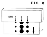
- Figs. 8 to 10 show a method of correcting differences between amounts of ink discharged from a plurality of nozzles of the ink-jet head IJH (called "bit correction", hereinafter).
- a nozzle 1, a nozzle 2 and a nozzle 3, for example, of the ink-jet head IJH is made discharge ink onto a predetermined plate P. Then, the sizes of ink dots made of the ink discharged from respective nozzles 1, 2 and 3 on the plate P are measured, and the amount of ink discharged from each nozzle is found.
- heat pulses (refer to Fig. 7) to be applied to heaters of the nozzles are first set to a fixed pulse width, and the preheat pulse widths (refer to Fig. 7) are changed as already described above. As a result, as shown in Fig.
- Figs. 11 to 13 show a method of correcting unevenness in printing in the scanning direction of the ink-jet head (called “shading correction", hereinafter) by adjusting density of dots (i.e., the number of dots printed in a unit area) printed by ink-discharging nozzles.
- the amount of ink discharged from the nozzle 3 of the ink-jet head is defined as reference
- the amount of ink discharged from the nozzle 1 is about 10% less then the reference
- the amount of ink discharged from the nozzle 2 is about 20% more than the reference.
- the heater of the nozzle 1 is applied with heat pulses once every nine reference clocks
- the heater of the nozzle 2 is applied with heat pulses once every 12 reference clocks
- the heater of the nozzle 3 is applied with heat pulses once every 10 reference clocks as shown in Fig. 12.
- the number of discharging operations in the scanning direction can be adjusted for each nozzle, thereby it is possible to set density of printed ink dots in the scanning direction to a uniform density, thus preventing unevenness in printing.
- shading correction To correct density of printed ink dots in the scanning direction as described above is called "shading correction". In this embodiment, this correction achieves correction range of the density of ink discharged by about 30% of the density. Further, it is possible to control the distance between each dots to be infinitely short (i.e., to increase resolution) theoretically. However, if doing so, the amount of data greatly increases, which makes the processing speed slower. Therefore, about 10% increase in resolution is the substantial limitation.
- the light source which emits white light is used.
- a proper band-pass filter which transmits light in red (R) wavelength range is placed between the light source and the dot, then absorbance of a dot is measured from the light transmitted through the band-pass filter and the dot (light in red wavelength range).
- R red
- to increase the tones of luminance levels may further increases accuracy of measured data.
- the image processing unit is used to measure the density of a dot in the aforesaid first and second embodiments, however, the present invention is not limited to this.
- transmitted light may be received by PMT (Photoelectron Magnification Tube), then the output from the PMT may be analog-digital converted into a signal in luminance level.
- PMT Photoelectron Magnification Tube
- A/D converter having higher resolution, better measurement accuracy can be achieved as mentioned in the second embodiment.
- luminance level (quantity of light) of the transmitted light is found as a density in the above embodiments, however, the present invention is not limited to the transmitted light, and reflected light received can be used instead.
- Fig. 14 depicts a configuration of a measuring apparatus according to a fourth embodiment of the present invention.
- reference numeral 201 denotes an image processing unit for measuring density
- 202 a personal computer (referred as "PC", hereinafter) used to control the image processing unit 201 and an X control stage 204
- 203 an optical system for magnifying an image
- 204 the X control stage used when densitys of an object subjected to measurement are measured continuously
- 205 a line sensor camera for inputting an image of the object subjected to measurement into the image processing unit 201
- 206 a light source set under the X control stage 204.
- the central part of the surface of the X control stage 204 is made of glass so that an image of the object to be measured can be inputted by the line sensor camera 205 by utilizing light from the light source 206.
- the PC 202 controls the X control stage 204 via RS232C or GPIB interface as well as controls the image processing unit 201.
- Fig. 15 shows a line pattern formed by discharging ink from a plurality of different nozzles of an ink-jet printer onto a transparent glass plate 210. Further, 'same nozzle direction' in Fig. 15 indicates the direction of ink lines discharged from an identical nozzle, and 'different nozzle direction' indicates the direction of ink discharged from a plurality of different nozzles. It should be noted that, since ink and glass are incompatible with each other, a special process for mediating between the discharged ink and the glass plate 210 is to be necessarily applied on the glass plate 210 (the glass plate is coated with polyvinyl alcohol to form an ink-absorbent layer 212 in this example).
- ink discharged from each nozzle is uniformly absorbed by the ink-absorbent layer 212 and forms the line pattern as shown in Fig. 15.
- a material which is as transparent and colorless as possible i.e., which do not absorb light is preferred.
- the optical system 203 focuses on an arbitrary line of the line pattern as shown in Fig. 15 and the magnification of the optical system 203 and the intensity of light from the light source 206 are properly adjusted. Under this condition, an image of the focused image is inputted by the line sensor camera 205 into the image processing unit 201.
- the magnification is 5, however, the present invention is not limited to this.
- the line sensor camera 205 in this embodiment is a black-and-white line sensor.
- An image inputted by this line sensor camera 205 consists of a collection of minimal pixel units that the image processing unit 201 can resolve, and each minimal pixel can represent luminance level in 256 tones, between 0 and 255 tones, in accordance with the intensity of the transmitted light.
- a line subjected to measurement inputted as described above by using the line sensor camera is enclosed by a fixed sized frame (called “window”, hereinafter) as shown in Fig. 16.
- window it is preferred to sum up all of the luminance levels of the minimal pixels of a line subjected to measurement to measure its density, however, when the line is actually observed through the microscope, it is very difficult to determine the border between the line and the background since the density in the edge part of the line is low. Therefore, a window whose size is large enough to include the entire line subjected to measurement (including its surrounding) is used to specify an area, then all the luminance levels of the minimal pixels in the window are summed up. The obtained sum is considered as a total luminance of the line subjected to measurement.
- the window size can be arbitrarily determined in consideration with the size of the line subjected to measurement. However, if the window size is set too large, the luminance level in too large background area which is essentially nothing to do with the line density is included, which degrades accuracy of the measured data. Therefore, too large window size is not preferable.
- the part which does not include the line pattern i.e., the part where only the ink-absorbent layer 12 exists
- the window of the same size shown in doted line
- This total luminance is defined as a reference total luminance which indicates a state in that light absorbance is the minimum (i.e., minimum density).
- the actually measured total luminance of the line subjected to measurement is divided by the reference total luminance, then the common logarithm of the reciprocal of the quotient is defined as the absorbance (density data) of the line subjected to measurement.
- Absorbance (density data) Log((reference total luminance) ⁇ (total luminance))
- Fig. 17 shows a case where the reference total luminance is found near the line pattern. According to experiments conducted by the applicants of the present invention, better result was obtained when the reference total luminance was calculated near the line pattern as shown in Fig. 17 than the reference total luminance was calculated in the area apart from the line patterns by some distance. The reason for this would be effect of the spatial distribution of the quantity of light from the light source.
- the line pattern can be continuously inputted. Thereafter, each line of the line pattern is marked with the window after inputting the line pattern, absorbances of all the lines of the line pattern can be found.
- a calibration line obtained in advance (a method of measuring the calibration line is the same as that in the first embodiment), it is easy to convert the density of each line of the line pattern into an amount of ink discharged in a single discharging operation by using the PC 202.
- line pattern density method a method of finding the amount of ink discharged in a single discharging operation based on the density of a line of the line pattern
- dot density method a method of finding an amount of ink discharged in a single discharging operation based on the density of an ink dot
- the obtained result is fed back to the printing apparatus so that printing on a printing medium is performed without unevenness in density of each ink dot by adjusting an amount of ink to be discharged by using an adjusting method as described in the first embodiment.
- the line sensor camera is used for inputting an image of the line pattern, however, a CCD camera, or other area sensors can be used instead. Further, by increasing the number of luminance levels used in the image processing operation (256 tones are used in the fourth embodiment), accuracy of the measured data can be further increased.
- Each apparatus described in the embodiments described above comprises means (e.g., an electrothermal transducer, laser beam generator, and the like) for generating heat energy as energy utilized upon execution of ink discharge, and causes a change in state of an ink by the heat energy, among the ink-jet printers.
- means e.g., an electrothermal transducer, laser beam generator, and the like
- heat energy as energy utilized upon execution of ink discharge
- causes a change in state of an ink by the heat energy among the ink-jet printers.
- the arrangement using U.S. Patent Nos. 4,558,333 and 4,459,600 which disclose the arrangement having a heat acting portion arranged in a flexed region is also included in the present invention.
- the present invention can be effectively applied to an arrangement based on Japanese Patent Laid-Open No. 59-123670 which discloses the arrangement using a slot common to a plurality of electrothermal transducers as a discharge portion of the electrothermal transducers, or Japanese Patent Laid-Open No. 59-138461 which discloses the arrangement having an opening for absorbing a pressure wave of heat energy in correspondence with a discharge portion.
- a full line type printhead having a length corresponding to the width of a maximum printing medium which can be printed by the printer
- either the arrangement which satisfies the full-line length by combining a plurality of printheads as disclosed in the above specification or the arrangement as a single printhead obtained by forming printheads integrally can be used.
- an exchangeable chip type printhead which can be electrically connected to the apparatus main unit and can receive an ink from the apparatus main unit upon being mounted on the apparatus main unit
- a cartridge type printhead in which an ink tank is integrally arranged on the printhead itself can be applicable to the present invention.
- recovery means for the printhead, preliminary auxiliary means, and the like provided as an arrangement of the printer of the present invention since the printing operation can be further stabilized.
- examples of such means include, for the printhead, capping means, cleaning means, pressurization or suction means, and preliminary heating means using electrothermal transducers, another heating element, or a combination thereof. It is also effective for stable printing to provide a preliminary discharge mode which performs discharge independently of printing.
- an ink may be situated opposite electrothermal transducers while being held in a liquid or solid state in recess portions of a porous sheet or through holes, as described in Japanese Patent Laid-Open No. 54-56847 or 60-71260.
- the above-mentioned film boiling system is most effective for the above-mentioned inks.
- the amount of ink discharged from an arbitrary nozzle can be easily found by referring to the correlation and the measured density of the ink dot or the line formed by the ink discharged from the nozzle.
- the density of the ink dot or the line pattern by forming ink dots or a line pattern on a transparent plate, inputting an image of them by using a camera while illuminating the ink dots or the line pattern with light, and applying image processing to the input image.
- the amount of ink discharged from an arbitrary nozzle under an arbitrary condition can be determined from the calibration line and the density of an ink dot or a line of a line pattern formed with the ink discharged from the arbitrary nozzle.
- the weighing method or the absorbance method can be used, thereby the amount of ink discharged from the nozzle can be correctly determined.
Landscapes
- Ink Jet (AREA)
- Particle Formation And Scattering Control In Inkjet Printers (AREA)
Applications Claiming Priority (6)
| Application Number | Priority Date | Filing Date | Title |
|---|---|---|---|
| JP131444/95 | 1995-05-30 | ||
| JP13144495 | 1995-05-30 | ||
| JP13144495 | 1995-05-30 | ||
| JP10541796A JP2907772B2 (ja) | 1995-05-30 | 1996-04-25 | インク吐出量の測定方法及び測定装置及びプリント装置及びプリント装置におけるインク吐出量の測定方法 |
| JP105417/96 | 1996-04-25 | ||
| JP10541796 | 1996-04-25 |
Publications (2)
| Publication Number | Publication Date |
|---|---|
| EP0747224A1 true EP0747224A1 (de) | 1996-12-11 |
| EP0747224B1 EP0747224B1 (de) | 2003-02-26 |
Family
ID=26445708
Family Applications (1)
| Application Number | Title | Priority Date | Filing Date |
|---|---|---|---|
| EP19960303812 Expired - Lifetime EP0747224B1 (de) | 1995-05-30 | 1996-05-29 | Messsystem der Menge ausgestossener Tinte während des Druckens |
Country Status (3)
| Country | Link |
|---|---|
| EP (1) | EP0747224B1 (de) |
| JP (1) | JP2907772B2 (de) |
| DE (1) | DE69626340D1 (de) |
Cited By (12)
| Publication number | Priority date | Publication date | Assignee | Title |
|---|---|---|---|---|
| EP0854039A3 (de) * | 1996-12-19 | 1999-05-19 | Canon Kabushiki Kaisha | Verfahren und Vorrichtung zum Messen der Menge ausgestossener Tinte, Druckvorrichtung und Verfahren zum Messen der Menge ausgestossener Tinte in der Druckvorrichtung |
| EP0832745A3 (de) * | 1996-09-30 | 1999-06-23 | Canon Kabushiki Kaisha | Tintenstrahldruckverfahren und Tintenstrahldruckvorrichtung, Farbfilter, Anzeigevorrichtung, Apparat mit einer Anzeigevorrichtung, Vorrichtung und Verfahren zum Justieren einer Tintenstrahlkopfeinheit und Tintenstrahlkopfeinheit |
| EP0900656A3 (de) * | 1997-08-26 | 1999-07-28 | Eastman Kodak Company | Drucken mit Tinte mit Trennung von Tropfen mit veränderlichem Volumen |
| EP1002655A3 (de) * | 1998-11-17 | 2001-03-14 | Pitney Bowes Inc. | Vorrichtung und Verfahren zur Echtzeitmessung der Qualität von Digitaldrucken |
| WO2001039486A1 (en) * | 1999-11-19 | 2001-05-31 | Koninklijke Philips Electronics N.V. | Multi-function monitoring module for a printer |
| US6270178B1 (en) | 1995-05-30 | 2001-08-07 | Canon Kabushiki Kaisha | Method and apparatus for measuring the amount of discharged ink, printing apparatus, and method of measuring the amount of ink discharged in the printing apparatus |
| WO2002004220A1 (en) * | 2000-07-10 | 2002-01-17 | Olivetti Tecnost S.P.A. | Ink jet printing system and method for controlling the printing quality |
| US6350006B1 (en) | 1998-11-17 | 2002-02-26 | Pitney Bowes Inc. | Optical ink drop detection apparatus and method for monitoring operation of an ink jet printhead |
| US6435642B1 (en) | 1998-11-17 | 2002-08-20 | Pitney Bowes Inc. | Apparatus and method for real-time measurement of digital print quality |
| US6582048B1 (en) | 1996-09-30 | 2003-06-24 | Canon Kabushiki Kaisha | Ink-jet print method and apparatus, color filter, display device, apparatus having display device, ink-jet head unit adjusting device and method, and ink-jet head unit |
| US6623095B1 (en) | 1996-08-01 | 2003-09-23 | Hewlett-Packard Company | Print-quality control method and system |
| EP3647060A4 (de) * | 2017-06-29 | 2020-06-17 | Konica Minolta, Inc. | Tintenabgabeoperationanpassungsverfahren und tintenstrahlaufzeichnungsvorrichtung |
Families Citing this family (17)
| Publication number | Priority date | Publication date | Assignee | Title |
|---|---|---|---|---|
| JP2002200741A (ja) * | 2000-12-28 | 2002-07-16 | Sony Corp | プリンタ |
| JP4865155B2 (ja) * | 2001-07-17 | 2012-02-01 | キヤノン株式会社 | 液滴量測定方法、液滴量測定装置及びそれを備えたインクジェットプリンタの製造システム |
| JP4722551B2 (ja) * | 2005-05-16 | 2011-07-13 | 日本電信電話株式会社 | 溶液吐出量評価装置及び方法 |
| JP4635842B2 (ja) * | 2005-11-16 | 2011-02-23 | セイコーエプソン株式会社 | 吐出パターンデータ補正方法、吐出パターンデータ補正装置、液滴吐出装置、並びに電気光学装置の製造方法 |
| JP2008080728A (ja) | 2006-09-28 | 2008-04-10 | Fujifilm Corp | インク吐出量測定方法及びインク吐出量測定システム |
| JP5073301B2 (ja) * | 2007-01-31 | 2012-11-14 | 東レエンジニアリング株式会社 | 塗布装置 |
| JP2009195868A (ja) * | 2008-02-25 | 2009-09-03 | Seiko Epson Corp | 吐出ヘッドの検査方法、吐出ヘッド検査装置及び描画方法 |
| JP4876287B2 (ja) * | 2008-03-27 | 2012-02-15 | 国立大学法人 大分大学 | 音響インピーダンス及び吸音率の測定方法 |
| JP5182280B2 (ja) * | 2009-12-25 | 2013-04-17 | セイコーエプソン株式会社 | 吐出パターンデータ補正方法 |
| JP5387598B2 (ja) * | 2011-03-10 | 2014-01-15 | セイコーエプソン株式会社 | 評価方法 |
| JP6966876B2 (ja) * | 2017-06-05 | 2021-11-17 | テラベース株式会社 | 極低温透過型電子顕微鏡用試料作成装置 |
| CN110126467B (zh) * | 2019-04-28 | 2021-06-11 | 华中科技大学 | 一种适用于大面积基板打印的融合墨液检测装置及方法 |
| JP7523036B2 (ja) * | 2020-07-27 | 2024-07-26 | パナソニックIpマネジメント株式会社 | 液滴観察装置およびミスト発生判定方法 |
| JP7710196B2 (ja) | 2020-10-07 | 2025-07-18 | パナソニックIpマネジメント株式会社 | 印刷装置及び印刷方法 |
| KR20240168963A (ko) | 2022-03-30 | 2024-12-02 | 파나소닉 아이피 매니지먼트 가부시키가이샤 | 인쇄 장치 및 인쇄 방법 |
| JP2024006461A (ja) | 2022-07-01 | 2024-01-17 | パナソニックIpマネジメント株式会社 | インクジェット装置、制御方法、及び、基板 |
| WO2024024342A1 (ja) | 2022-07-25 | 2024-02-01 | パナソニックIpマネジメント株式会社 | 印刷装置、制御装置及び印刷方法 |
Citations (2)
| Publication number | Priority date | Publication date | Assignee | Title |
|---|---|---|---|---|
| EP0461759A2 (de) * | 1990-05-11 | 1991-12-18 | Canon Kabushiki Kaisha | Aufzeichnungsgerät mit Aufzeichnungskopf |
| US5387976A (en) * | 1993-10-29 | 1995-02-07 | Hewlett-Packard Company | Method and system for measuring drop-volume in ink-jet printers |
-
1996
- 1996-04-25 JP JP10541796A patent/JP2907772B2/ja not_active Expired - Fee Related
- 1996-05-29 EP EP19960303812 patent/EP0747224B1/de not_active Expired - Lifetime
- 1996-05-29 DE DE69626340T patent/DE69626340D1/de not_active Expired - Lifetime
Patent Citations (2)
| Publication number | Priority date | Publication date | Assignee | Title |
|---|---|---|---|---|
| EP0461759A2 (de) * | 1990-05-11 | 1991-12-18 | Canon Kabushiki Kaisha | Aufzeichnungsgerät mit Aufzeichnungskopf |
| US5387976A (en) * | 1993-10-29 | 1995-02-07 | Hewlett-Packard Company | Method and system for measuring drop-volume in ink-jet printers |
Cited By (15)
| Publication number | Priority date | Publication date | Assignee | Title |
|---|---|---|---|---|
| US6270178B1 (en) | 1995-05-30 | 2001-08-07 | Canon Kabushiki Kaisha | Method and apparatus for measuring the amount of discharged ink, printing apparatus, and method of measuring the amount of ink discharged in the printing apparatus |
| US6623095B1 (en) | 1996-08-01 | 2003-09-23 | Hewlett-Packard Company | Print-quality control method and system |
| EP0832745A3 (de) * | 1996-09-30 | 1999-06-23 | Canon Kabushiki Kaisha | Tintenstrahldruckverfahren und Tintenstrahldruckvorrichtung, Farbfilter, Anzeigevorrichtung, Apparat mit einer Anzeigevorrichtung, Vorrichtung und Verfahren zum Justieren einer Tintenstrahlkopfeinheit und Tintenstrahlkopfeinheit |
| US6582048B1 (en) | 1996-09-30 | 2003-06-24 | Canon Kabushiki Kaisha | Ink-jet print method and apparatus, color filter, display device, apparatus having display device, ink-jet head unit adjusting device and method, and ink-jet head unit |
| EP0854039A3 (de) * | 1996-12-19 | 1999-05-19 | Canon Kabushiki Kaisha | Verfahren und Vorrichtung zum Messen der Menge ausgestossener Tinte, Druckvorrichtung und Verfahren zum Messen der Menge ausgestossener Tinte in der Druckvorrichtung |
| US6498615B1 (en) | 1997-08-26 | 2002-12-24 | Eastman Kodak Company | Ink printing with variable drop volume separation |
| EP0900656A3 (de) * | 1997-08-26 | 1999-07-28 | Eastman Kodak Company | Drucken mit Tinte mit Trennung von Tropfen mit veränderlichem Volumen |
| EP1002655A3 (de) * | 1998-11-17 | 2001-03-14 | Pitney Bowes Inc. | Vorrichtung und Verfahren zur Echtzeitmessung der Qualität von Digitaldrucken |
| US6435642B1 (en) | 1998-11-17 | 2002-08-20 | Pitney Bowes Inc. | Apparatus and method for real-time measurement of digital print quality |
| US6350006B1 (en) | 1998-11-17 | 2002-02-26 | Pitney Bowes Inc. | Optical ink drop detection apparatus and method for monitoring operation of an ink jet printhead |
| US6561612B2 (en) | 1998-11-17 | 2003-05-13 | Pitney Bowes Inc. | Apparatus and method for real-time measurement of digital print quality |
| WO2001039486A1 (en) * | 1999-11-19 | 2001-05-31 | Koninklijke Philips Electronics N.V. | Multi-function monitoring module for a printer |
| WO2002004220A1 (en) * | 2000-07-10 | 2002-01-17 | Olivetti Tecnost S.P.A. | Ink jet printing system and method for controlling the printing quality |
| US6886902B2 (en) | 2000-07-10 | 2005-05-03 | Olivetti Tecnost S.P.A. | Ink jet printing system and method for controlling the printing quality |
| EP3647060A4 (de) * | 2017-06-29 | 2020-06-17 | Konica Minolta, Inc. | Tintenabgabeoperationanpassungsverfahren und tintenstrahlaufzeichnungsvorrichtung |
Also Published As
| Publication number | Publication date |
|---|---|
| JP2907772B2 (ja) | 1999-06-21 |
| JPH0948111A (ja) | 1997-02-18 |
| DE69626340D1 (de) | 2003-04-03 |
| EP0747224B1 (de) | 2003-02-26 |
Similar Documents
| Publication | Publication Date | Title |
|---|---|---|
| EP0747224B1 (de) | Messsystem der Menge ausgestossener Tinte während des Druckens | |
| US6270178B1 (en) | Method and apparatus for measuring the amount of discharged ink, printing apparatus, and method of measuring the amount of ink discharged in the printing apparatus | |
| US5528270A (en) | Method for correcting density unevenness for a recording head and an image formation apparatus provided with such a method | |
| US6645029B2 (en) | Color filter producing method and apparatus | |
| KR100253258B1 (ko) | 컬러 필터를 제조하기 위한 방법 및 장치,컬러 필터, 디스플레이 디바이스, 및이 디스플레이 디바이스를갖는 장치 | |
| US20030001918A1 (en) | Calibration method in ink jet printing apparatus | |
| US6431679B1 (en) | Calibration of print contrast using an optical-electronic sensor | |
| JPH10329381A (ja) | プリント装置およびプリント位置合わせ方法 | |
| JP4323580B2 (ja) | プリント装置およびそのヘッド駆動方法 | |
| KR19990014211A (ko) | 컬러-필터의 제조방법, 컬러 필터, 디스플레이 장치, 및 상기 디스플레이 장치를 포함한 장치 | |
| US8393704B2 (en) | Method for calibrating an inkjet printer and print product | |
| EP0942591A1 (de) | Bildverarbeitungsverfahren und -gerät, und Druckverfahren und Drucker | |
| EP1027679B1 (de) | Verfahren und vorrichtung zur kalibrierung eines bilderzeugungsgeräts mit mehreren bildausgängen | |
| JP4323587B2 (ja) | プリント位置合わせ方法、プリント装置およびプリントシステム | |
| KR100338616B1 (ko) | 칼라 필터 제조 장치 및 방법, 칼라 필터, 표시 장치,표시 장치를 구비한 장치, 및 잉크 순환에 의한 복수개의노즐간의 토출 체적 불균일성 감소 방법 | |
| EP0854039B1 (de) | Verfahren und Vorrichtung zum Messen der Menge ausgestossener Tinte, Druckvorrichtung und Verfahren zum Messen der Menge ausgestossener Tinte in der Druckvorrichtung | |
| US6211970B1 (en) | Binary printer with halftone printing temperature correction | |
| JPH0843174A (ja) | 検出装置、記録装置、容器、インクカートリッジ及び検出方法 | |
| US6886902B2 (en) | Ink jet printing system and method for controlling the printing quality | |
| JP2904343B2 (ja) | インク吐出量の測定方法及び測定装置及びプリント装置及びプリント装置におけるインク吐出量の測定方法 | |
| JP2938934B2 (ja) | 画像形成装置 | |
| JP2001105635A (ja) | プリント位置合わせ方法およびプリント装置 | |
| US5909229A (en) | Recording apparatus in which pressure interference between closely-spaced ink jets is reduced | |
| JP2001287351A (ja) | 印字マスクを生成する方法 | |
| JP2915081B2 (ja) | 画像形成装置 |
Legal Events
| Date | Code | Title | Description |
|---|---|---|---|
| PUAI | Public reference made under article 153(3) epc to a published international application that has entered the european phase |
Free format text: ORIGINAL CODE: 0009012 |
|
| AK | Designated contracting states |
Kind code of ref document: A1 Designated state(s): DE FR GB IT |
|
| 17P | Request for examination filed |
Effective date: 19970423 |
|
| 17Q | First examination report despatched |
Effective date: 19980820 |
|
| GRAG | Despatch of communication of intention to grant |
Free format text: ORIGINAL CODE: EPIDOS AGRA |
|
| GRAG | Despatch of communication of intention to grant |
Free format text: ORIGINAL CODE: EPIDOS AGRA |
|
| GRAH | Despatch of communication of intention to grant a patent |
Free format text: ORIGINAL CODE: EPIDOS IGRA |
|
| GRAH | Despatch of communication of intention to grant a patent |
Free format text: ORIGINAL CODE: EPIDOS IGRA |
|
| GRAA | (expected) grant |
Free format text: ORIGINAL CODE: 0009210 |
|
| AK | Designated contracting states |
Designated state(s): DE FR GB IT |
|
| PG25 | Lapsed in a contracting state [announced via postgrant information from national office to epo] |
Ref country code: IT Free format text: LAPSE BECAUSE OF FAILURE TO SUBMIT A TRANSLATION OF THE DESCRIPTION OR TO PAY THE FEE WITHIN THE PRESCRIBED TIME-LIMIT;WARNING: LAPSES OF ITALIAN PATENTS WITH EFFECTIVE DATE BEFORE 2007 MAY HAVE OCCURRED AT ANY TIME BEFORE 2007. THE CORRECT EFFECTIVE DATE MAY BE DIFFERENT FROM THE ONE RECORDED. Effective date: 20030226 Ref country code: FR Free format text: LAPSE BECAUSE OF NON-PAYMENT OF DUE FEES Effective date: 20030226 |
|
| REG | Reference to a national code |
Ref country code: GB Ref legal event code: FG4D |
|
| REF | Corresponds to: |
Ref document number: 69626340 Country of ref document: DE Date of ref document: 20030403 Kind code of ref document: P |
|
| PG25 | Lapsed in a contracting state [announced via postgrant information from national office to epo] |
Ref country code: DE Free format text: LAPSE BECAUSE OF FAILURE TO SUBMIT A TRANSLATION OF THE DESCRIPTION OR TO PAY THE FEE WITHIN THE PRESCRIBED TIME-LIMIT Effective date: 20030527 |
|
| PLBE | No opposition filed within time limit |
Free format text: ORIGINAL CODE: 0009261 |
|
| STAA | Information on the status of an ep patent application or granted ep patent |
Free format text: STATUS: NO OPPOSITION FILED WITHIN TIME LIMIT |
|
| EN | Fr: translation not filed | ||
| 26N | No opposition filed |
Effective date: 20031127 |
|
| PGFP | Annual fee paid to national office [announced via postgrant information from national office to epo] |
Ref country code: GB Payment date: 20140523 Year of fee payment: 19 |
|
| GBPC | Gb: european patent ceased through non-payment of renewal fee |
Effective date: 20150529 |
|
| PG25 | Lapsed in a contracting state [announced via postgrant information from national office to epo] |
Ref country code: GB Free format text: LAPSE BECAUSE OF NON-PAYMENT OF DUE FEES Effective date: 20150529 |