EP0747244A1 - Kupplungsvorrichtung zum Kuppeln eines Anhängers an ein Zugfahrzeug und Anhängerteil, geeignet für eine solche Kupplungsvorrichtung - Google Patents
Kupplungsvorrichtung zum Kuppeln eines Anhängers an ein Zugfahrzeug und Anhängerteil, geeignet für eine solche Kupplungsvorrichtung Download PDFInfo
- Publication number
- EP0747244A1 EP0747244A1 EP96201539A EP96201539A EP0747244A1 EP 0747244 A1 EP0747244 A1 EP 0747244A1 EP 96201539 A EP96201539 A EP 96201539A EP 96201539 A EP96201539 A EP 96201539A EP 0747244 A1 EP0747244 A1 EP 0747244A1
- Authority
- EP
- European Patent Office
- Prior art keywords
- vehicle
- coupling
- trailer
- coupling device
- moved
- Prior art date
- Legal status (The legal status is an assumption and is not a legal conclusion. Google has not performed a legal analysis and makes no representation as to the accuracy of the status listed.)
- Withdrawn
Links
Images


Classifications
-
- B—PERFORMING OPERATIONS; TRANSPORTING
- B60—VEHICLES IN GENERAL
- B60D—VEHICLE CONNECTIONS
- B60D1/00—Traction couplings; Hitches; Draw-gear; Towing devices
- B60D1/24—Traction couplings; Hitches; Draw-gear; Towing devices characterised by arrangements for particular functions
- B60D1/36—Traction couplings; Hitches; Draw-gear; Towing devices characterised by arrangements for particular functions for facilitating connection, e.g. hitch catchers
- B60D1/363—Hitch guiding or catching elements, e.g. V-shaped plates partially surrounding a coupling member for guiding the other coupling member
-
- B—PERFORMING OPERATIONS; TRANSPORTING
- B60—VEHICLES IN GENERAL
- B60D—VEHICLE CONNECTIONS
- B60D1/00—Traction couplings; Hitches; Draw-gear; Towing devices
- B60D1/48—Traction couplings; Hitches; Draw-gear; Towing devices characterised by the mounting
- B60D1/52—Traction couplings; Hitches; Draw-gear; Towing devices characterised by the mounting removably mounted
-
- B—PERFORMING OPERATIONS; TRANSPORTING
- B60—VEHICLES IN GENERAL
- B60D—VEHICLE CONNECTIONS
- B60D1/00—Traction couplings; Hitches; Draw-gear; Towing devices
- B60D1/48—Traction couplings; Hitches; Draw-gear; Towing devices characterised by the mounting
- B60D1/54—Traction couplings; Hitches; Draw-gear; Towing devices characterised by the mounting collapsible or retractable when not in use, e.g. hide-away hitches
-
- B—PERFORMING OPERATIONS; TRANSPORTING
- B60—VEHICLES IN GENERAL
- B60D—VEHICLE CONNECTIONS
- B60D1/00—Traction couplings; Hitches; Draw-gear; Towing devices
- B60D1/58—Auxiliary devices
- B60D1/62—Auxiliary devices involving supply lines, electric circuits or the like
- B60D1/64—Couplings or joints therefor
Definitions
- the invention relates to a coupling device suitable for coupling a vehicle and a trailer to be moved by said vehicle, which coupling device is provided with a vehicle part to be secured to said vehicle, and with a trailer part to be secured to said trailer, whereby said trailer part can be detachably coupled to said vehicle part.
- the invention also relates to a vehicle part and to a trailer part suitable for such a coupling device.
- tractor used herein is understood to mean a loading platform supported by wheels, a caravan, a collapsible caravan, a bicycle carrier, a luggage container or another construction which is coupled to a vehicle and which functions to extend the transport capacity of the vehicle.
- the vehicle part of a coupling device known per se is provided with a towbar comprising a ball, and the trailer part is provided with a cup-shaped cap, also called the coupling head, which engages around said ball.
- a drawback of such a coupling device is that people frequently bump into the towbar protruding from the vehicle and soil their clothes in the uncoupled position of the coupling device.
- the towbar defaces the rear side of the vehicle, and in the case of a relatively minor collision the towbar rather than a bumper of the vehicle will absorb the impact. This is undesirable in connection with possible damage to the supporting frame parts.
- a partial solution for this problem is provided by a so-called detachable towbar.
- the towbar may be removed from the vehicle after use.
- a drawback of a detachable towbar is the fact that detaching is laborious, as a result of which the towbar is frequently left in place in practice. In addition to that the presence of dirt and grease on the detached towbar make it undesirable to put the towbar in the vehicle.
- Detachable towbars of this type are known, inter alia from European Patent Applications EP-A1-0 533 270 and EP-A2-0 455 251.
- a detachable towbar and a part fixed to the trailer are needed in order to couple the vehicle and the trailer, however, which makes the coupling device relatively complicated.
- it is necessary to realize a separate electric connection between vehicle and trailer after the two have been mechanically coupled Generally this is done by connecting an electric lead, which is connected to the trailer, to a coupler socket on the vehicle by means of a plug. The lead hangs loose in the uncoupled position of the trailer, with the risk of the plug being damaged or becoming fouled.
- Another drawback of the electric connection which is known per se, is that the connection must be effected independently of the mechanical connection.
- the object of the invention is to provide a coupling device wherein the presence of projecting parts on the vehicle and of loose parts is avoided, whilst a mechanical and electric coupling between the vehicle and the container is obtained in a simple manner.
- the vehicle part comprises a tubular housing bounding a recess
- the trailer part comprises a coupling part, which can be partially slid into said recess and which can be locked with respect to said tubular housing, whereby said tubular housing and said coupling part are provided with electric contacts, which can be electrically connected by means of the coupling part which can be slid into said housing.
- the vehicle no longer comprises any projecting parts and the trailer can be coupled to the vehicle in a simple manner by sliding the coupling part into a tubular housing and locking it therein. There will be no loose parts after the trailer is uncoupled from the vehicle.
- One embodiment of the coupling device according to the invention is characterized in that the trailer part comprises an attaching part which is pivoted to said coupling part, which attaching part can be attached to a trailer.
- the trailer and the attaching part attached thereto are capable of pivoting movement with respect to the vehicle and with respect to the coupling part coupled to said vehicle.
- the pivoting function is provided on the trailer.
- FIG. 1 Another embodiment of a coupling device according to the invention is characterized in that said coupling part and said attaching part are pivotally interconnected by means of a ball, which is secured to one part, and a ring engaging around said ball, which is secured to another part.
- Said ball and said ring engaging around said ball form a relatively simple, reliable hinge between the coupling part and the attaching part. Said ball and said ring cannot be detached from each other other than for maintenance purposes.
- Another embodiment of the coupling device is characterized in that the coupling part is connected to the attaching part by means of at least one viscous damper.
- the viscous damper slows down relatively quick pivoting movements of the attaching part with respect to the coupling part, whilst relatively slow pivoting movements can take place without impediment.
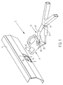
- FIG 1 is a perspective view of a coupling device according to the invention.
- the coupling device 1 is provided with a vehicle part 3 and a trailer part 5.
- the vehicle part 3 is attached to a vehicle, a rear bumper 7 of which is shown in the Figure.
- Vehicle part 3 comprises a tubular housing 9, which bounds a funnel-shaped recess 11 and which is provided with a slot 15 formed in a wall 13 thereof.
- Tubular housing 9 is fully recessed in rear bumper 7 and can be hidden from view by means of a covering cap (not shown).
- Figure 5 is a larger-scale perspective view of vehicle part 3.
- Trailer part 5 comprises a coupling part 17 and an attaching part 19 which is pivoted to said coupling part 17, which attaching part is attached to a caravan (not shown), for example.
- Coupling part 17 comprises a guide 21 shaped to be complementary to funnel-shaped recess 11, as well as a rectangular plug 23 extending from said guide. Coupling part 17 furthermore comprises a ball 25, around which a ring 29 engages, which ring is connected to said attaching part via a rod 27. Coupling part 17 and attaching part 19 are capable of pivoting movement with respect to each other via ball 25 and ring 29. Ball 25 and ring 29 are undetachably interconnected. The two parts 17 and 19 of trailer part 5 are also interconnected by means of two viscous dampers 31.
- guide 21 of coupling part 17 is slid into the funnel-shaped recess 11 of tubular housing 9. Due to the funnel shape it is relatively simple to insert guide 21 into recess 11.
- coupling device 1 The operation of coupling device 1 will be explained in more detail with reference to Figures 2A, 2B and 2C. Said Figures 2A, 2B and 2C illustrate the coupling, the coupled position and the uncoupling respectively.
- locking mechanism 35 comprises an unlocking slide 37, an operating slide 39, which is capable of movement parallel to unlocking slide 37, and a locking pin 41 which is capable of movement transversely thereto.
- Unlocking slide 37, operating slide 39 and locking pin 41 are shown in more detail in Figure 4. Slides 37 and 39 are supported in recesses 38, 40 of locking pin 41.
- unlocking pin 37 By moving coupling device 1 further in the direction indicated by arrow P1, one end of unlocking pin 37 comes into contact with a stop 43 positioned within housing 9, and is then moved in a direction indicated by arrow P2 against the spring force of a spring 45. Locking pin 41 butts with a surface 47 against a surface 49 of unlocking slide 37 under the spring force of a spring 51. Surface 49 is slid under surface 47 by moving unlocking slide 37, as a result of which locking pin 41 is moved in a direction indicated by arrow P3, into slot 15 of housing 9, by a spring force exerted by spring 51, as a result of which coupling part 17 is mechanically connected to housing 9.
- Figure 2B shows the mechanical and the electric coupling of vehicle part 3 to trailer part 5.
- the sloping surfaces 53, 55 prevent locking pin 41 from slipping out of slot 15.
- FIG. 2C shows the uncoupling of coupling device 1.
- an unlocking mechanism 65 is activated, which inter alia comprises the grip 33, which is capable of pivoting movement about a pivot 67 of coupling part 17.
- Unlocking mechanism 65 is activated by moving a knob 71 provided in grip 33 in a direction indicated by arrow P5 against a spring force exerted by a spring 69, as a result of which a lever 73 is pivoted about a pivot 75 and a catch 77 provided on lever 73, by means of which grip 33 is locked with respect to coupling part 17, is released from a notch 79 in coupling part 17.
- grip 33 is pivoted about pivot 67 in a direction indicated by arrow P6 against a spring force exerted by a spring 81.
- One end of a second lever 85 is movably mounted on grip 33 via a pin 83.
- the end of the second lever 85 is provided with a slot 87, in which pin 83 is supported.
- Another end of lever 85 is provided with a slot 89, in which a pin 91 is supported, which also engages in a groove 93 formed in operating slide 39.
- Lever 85 is capable of tilting movement about a pivot 95.
- Lever 85 is tilted about pivot 95 by moving grip 33 in the direction indicated by arrow P6, as a result of which operating slide 39 is moved in a direction indicated by arrow P7 against a spring force exerted by spring 57.
- a sloping surface 97 of operating slide 39 thereby comes into contact with a sloping surface 99 of locking pin 41, as a result of which locking pin 41 is moved in a direction indicated by arrow P8 against a spring force indicated by spring 51, and is moved out of slot 15 of vehicle part 3.
- trailer part 5 is moved in a direction indicated by arrow P9, as a result of which trailer part 5 is uncoupled from vehicle part 3.
- Unlocking slide 37 is moved in a direction indicated by arrow P10 against the spring force exerted by spring 45, and surface 49 is moved under surface 47 of locking pin 41, as a result of which locking pin 41 is locked in position.
- FIG 3 is a plan view of the coupled position of coupling device 1 shown in Figure 2.
- Dampers 31 each comprise a cylinder 101 and a piston 103, which is capable of movement within cylinder 101. Cylinders 101 are pivoted, via pivots 105, to attaching part 19 with their ends facing away from pistons 103. Pistons 103 are pivoted, via pivots 107, to coupling part 17 with their ends facing away from cylinders 101. Viscous dampers 31 prevent attaching part 19 from making relatively quick pivoting movements with respect to coupling part 17. Relatively slow movements are possible, however.
- Figure 6 shows an embodiment of a vehicle part 5 provided with a tubular housing 9, which is secured to a tubular section 109.
- Vehicle part 3 is secured to a vehicle by means of bolts inserted through holes 113 and flanges 111 extending parallel to and transversely to tubular section 109.
- the coupling device 1 may be made of plastic material or of a metal, for example.
- the coupling part of the trailer part with a bicycle rack or a luggage container.
- the trailer part does not comprise an attaching part which is pivoted to the coupling part.
- the proposed coupling device comprising a pivoted attaching part makes it possible to place the pivoting point of the trailer with respect to the vehicle closer to the vehicle than with a known towbar, which results in an improved road-holding of the vehicle and trailer.
Landscapes
- Engineering & Computer Science (AREA)
- Transportation (AREA)
- Mechanical Engineering (AREA)
- Vehicle Cleaning, Maintenance, Repair, Refitting, And Outriggers (AREA)
Applications Claiming Priority (2)
| Application Number | Priority Date | Filing Date | Title |
|---|---|---|---|
| NL1000504A NL1000504C2 (nl) | 1995-06-07 | 1995-06-07 | Koppelinrichting geschikt voor het koppelen van een voertuig en een door het voertuig te verplaatsen aanhanger, alsmede voertuigdeel en aanhangerdeel geschikt voor een dergelijke koppelinrichting. |
| NL1000504 | 1995-06-07 |
Publications (1)
| Publication Number | Publication Date |
|---|---|
| EP0747244A1 true EP0747244A1 (de) | 1996-12-11 |
Family
ID=19761122
Family Applications (1)
| Application Number | Title | Priority Date | Filing Date |
|---|---|---|---|
| EP96201539A Withdrawn EP0747244A1 (de) | 1995-06-07 | 1996-06-03 | Kupplungsvorrichtung zum Kuppeln eines Anhängers an ein Zugfahrzeug und Anhängerteil, geeignet für eine solche Kupplungsvorrichtung |
Country Status (2)
| Country | Link |
|---|---|
| EP (1) | EP0747244A1 (de) |
| NL (1) | NL1000504C2 (de) |
Cited By (9)
| Publication number | Priority date | Publication date | Assignee | Title |
|---|---|---|---|---|
| EP1757488A3 (de) * | 2005-08-25 | 2007-04-04 | WESTFALIA - Automotive GmbH | Trägeranordnung für ein Kraftfahrzeug und Halteranordnung dafür |
| WO2007091222A1 (en) * | 2006-02-10 | 2007-08-16 | Jakobus Nikolaas Steenkamp | Tow hitch |
| WO2012019955A1 (fr) * | 2010-08-11 | 2012-02-16 | Olivier Subrin | Système d'interconnection électromécanique. |
| EP2428404A1 (de) * | 2010-09-13 | 2012-03-14 | WESTFALIA - Automotive GmbH | Lastenträger-System |
| EP2431201A1 (de) * | 2010-09-20 | 2012-03-21 | Voith Patent GmbH | Kupplungskopf einer Kupplungsvorrichtung zum mechanischen Verbinden von zwei Einheiten, insbesondere Fahrzeugeinheiten |
| EP2428405A3 (de) * | 2010-09-13 | 2013-01-02 | WESTFALIA - Automotive GmbH | Kupplung für ein Lastenträger-System mit einem Spannteil |
| EP2428403A3 (de) * | 2010-09-13 | 2013-01-02 | WESTFALIA - Automotive GmbH | Kupplung für ein Lastenträger-System mit einer Kontakteinheit |
| EP2913208A1 (de) * | 2014-03-01 | 2015-09-02 | WESTFALIA - Automotive GmbH | Anhängekupplung mit einer Fahrzeug-Kontakteinheit |
| US11787246B2 (en) | 2020-08-07 | 2023-10-17 | Jon L. Whipple | Stabilizer system for an off-road trailer |
Citations (7)
| Publication number | Priority date | Publication date | Assignee | Title |
|---|---|---|---|---|
| US4603878A (en) * | 1984-11-20 | 1986-08-05 | Smith Jr Hoke | Automatic locking and centering wide range tow hitch |
| US4666177A (en) * | 1986-05-14 | 1987-05-19 | Beryl Vinchattle | Hitch |
| EP0231551A1 (de) * | 1985-12-20 | 1987-08-12 | Tobo Made B.V. | Trennbare Anhängerkupplung |
| EP0455251A2 (de) * | 1990-05-04 | 1991-11-06 | Al-Ko Kober Ag | Abnehmbare Anhängerkupplung |
| US5184839A (en) * | 1991-04-24 | 1993-02-09 | Guedry Harry R | Speedy hitch kit |
| EP0533270A1 (de) * | 1991-09-19 | 1993-03-24 | Jan Bolland | Anhängerkupplungsvorrichtung mit abnehmbarer Kugelkopfstange |
| EP0646482A1 (de) * | 1993-09-30 | 1995-04-05 | PLINI & GIGLIOTTI S.n.c. | Abnehmbare Kupplungsstange |
-
1995
- 1995-06-07 NL NL1000504A patent/NL1000504C2/xx not_active IP Right Cessation
-
1996
- 1996-06-03 EP EP96201539A patent/EP0747244A1/de not_active Withdrawn
Patent Citations (7)
| Publication number | Priority date | Publication date | Assignee | Title |
|---|---|---|---|---|
| US4603878A (en) * | 1984-11-20 | 1986-08-05 | Smith Jr Hoke | Automatic locking and centering wide range tow hitch |
| EP0231551A1 (de) * | 1985-12-20 | 1987-08-12 | Tobo Made B.V. | Trennbare Anhängerkupplung |
| US4666177A (en) * | 1986-05-14 | 1987-05-19 | Beryl Vinchattle | Hitch |
| EP0455251A2 (de) * | 1990-05-04 | 1991-11-06 | Al-Ko Kober Ag | Abnehmbare Anhängerkupplung |
| US5184839A (en) * | 1991-04-24 | 1993-02-09 | Guedry Harry R | Speedy hitch kit |
| EP0533270A1 (de) * | 1991-09-19 | 1993-03-24 | Jan Bolland | Anhängerkupplungsvorrichtung mit abnehmbarer Kugelkopfstange |
| EP0646482A1 (de) * | 1993-09-30 | 1995-04-05 | PLINI & GIGLIOTTI S.n.c. | Abnehmbare Kupplungsstange |
Cited By (12)
| Publication number | Priority date | Publication date | Assignee | Title |
|---|---|---|---|---|
| EP1757488A3 (de) * | 2005-08-25 | 2007-04-04 | WESTFALIA - Automotive GmbH | Trägeranordnung für ein Kraftfahrzeug und Halteranordnung dafür |
| EP2266842A3 (de) * | 2005-08-25 | 2011-04-06 | WESTFALIA - Automotive GmbH | Trägeranordnung für ein Kraftfahrzeug und Halteranordnung dafür |
| EP2284042A3 (de) * | 2005-08-25 | 2011-04-06 | WESTFALIA - Automotive GmbH | Trägeranordnung für ein Kraftfahrzeug und Halteranordnung dafür |
| WO2007091222A1 (en) * | 2006-02-10 | 2007-08-16 | Jakobus Nikolaas Steenkamp | Tow hitch |
| WO2012019955A1 (fr) * | 2010-08-11 | 2012-02-16 | Olivier Subrin | Système d'interconnection électromécanique. |
| EP2428404A1 (de) * | 2010-09-13 | 2012-03-14 | WESTFALIA - Automotive GmbH | Lastenträger-System |
| EP2428405A3 (de) * | 2010-09-13 | 2013-01-02 | WESTFALIA - Automotive GmbH | Kupplung für ein Lastenträger-System mit einem Spannteil |
| EP2428403A3 (de) * | 2010-09-13 | 2013-01-02 | WESTFALIA - Automotive GmbH | Kupplung für ein Lastenträger-System mit einer Kontakteinheit |
| EP2431201A1 (de) * | 2010-09-20 | 2012-03-21 | Voith Patent GmbH | Kupplungskopf einer Kupplungsvorrichtung zum mechanischen Verbinden von zwei Einheiten, insbesondere Fahrzeugeinheiten |
| CN102407863A (zh) * | 2010-09-20 | 2012-04-11 | 沃依特专利有限责任公司 | 用于机械地连接两个单元的连接装置的车钩头 |
| EP2913208A1 (de) * | 2014-03-01 | 2015-09-02 | WESTFALIA - Automotive GmbH | Anhängekupplung mit einer Fahrzeug-Kontakteinheit |
| US11787246B2 (en) | 2020-08-07 | 2023-10-17 | Jon L. Whipple | Stabilizer system for an off-road trailer |
Also Published As
| Publication number | Publication date |
|---|---|
| NL1000504C2 (nl) | 1996-12-10 |
Similar Documents
| Publication | Publication Date | Title |
|---|---|---|
| US6135482A (en) | Hitch adapter | |
| EP0747244A1 (de) | Kupplungsvorrichtung zum Kuppeln eines Anhängers an ein Zugfahrzeug und Anhängerteil, geeignet für eine solche Kupplungsvorrichtung | |
| US5277447A (en) | Trailer hitch with alignment adapter | |
| CN100425463C (zh) | 将两个车辆连接在一起的联结装置 | |
| US6575101B2 (en) | Coupling arrangement for a train of highway trailers | |
| MXPA00000901A (es) | Conjunto de enganche y remolque. | |
| US20020109335A1 (en) | Gooseneck coupler | |
| US20030015855A1 (en) | Fifth wheel hitch assembly with improved jaw mechanism | |
| CA2159945A1 (en) | Weight distributing hitch assembly | |
| US4666177A (en) | Hitch | |
| CA2399549A1 (en) | Fifth wheel hitch with rocker | |
| US6637765B2 (en) | Towing safety device | |
| US6179318B1 (en) | Hitch guide | |
| JP7703598B2 (ja) | 物体検出手段が取り付けられた牽引車両用の連結装置 | |
| US5094485A (en) | Retractable self-latching locking pin assembly | |
| US7543837B2 (en) | Single handed controlled trailer hitch | |
| US6186532B1 (en) | Trailer coupler | |
| US4893829A (en) | Self aligning coupling apparatus | |
| CA1307238C (en) | Quick connect/disconnect wheel cradle arrangement for wheel lift towing systems | |
| CN108367646A (zh) | 具有用于自动建立插接连接的可相对于挂接构件体运动的插接和对准构件的挂接构件 | |
| US7748548B1 (en) | Hitch assembly for a transporter | |
| CA2305916C (en) | Trailer coupler | |
| US4407617A (en) | Combination manual and automatic unlocking mechanism for trailer hitch head | |
| US20040070170A1 (en) | Jaw assembly for fifth wheel hitch assembly | |
| FI65039C (fi) | Skyddsanordning foer anslutning till bakaenden av en traktorstomme |
Legal Events
| Date | Code | Title | Description |
|---|---|---|---|
| PUAI | Public reference made under article 153(3) epc to a published international application that has entered the european phase |
Free format text: ORIGINAL CODE: 0009012 |
|
| AK | Designated contracting states |
Kind code of ref document: A1 Designated state(s): AT BE DE FR GB IT NL SE |
|
| STAA | Information on the status of an ep patent application or granted ep patent |
Free format text: STATUS: THE APPLICATION HAS BEEN WITHDRAWN |
|
| 17P | Request for examination filed |
Effective date: 19970606 |
|
| 18W | Application withdrawn |
Withdrawal date: 19970620 |