EP0747276B2 - Système automatique de freinage à logique floue pour avion - Google Patents
Système automatique de freinage à logique floue pour avion Download PDFInfo
- Publication number
- EP0747276B2 EP0747276B2 EP96201088A EP96201088A EP0747276B2 EP 0747276 B2 EP0747276 B2 EP 0747276B2 EP 96201088 A EP96201088 A EP 96201088A EP 96201088 A EP96201088 A EP 96201088A EP 0747276 B2 EP0747276 B2 EP 0747276B2
- Authority
- EP
- European Patent Office
- Prior art keywords
- error
- control signal
- fuzzy
- aircraft
- slope
- Prior art date
- Legal status (The legal status is an assumption and is not a legal conclusion. Google has not performed a legal analysis and makes no representation as to the accuracy of the status listed.)
- Expired - Lifetime
Links
- 238000011156 evaluation Methods 0.000 claims description 3
- 230000007704 transition Effects 0.000 claims description 2
- 238000004422 calculation algorithm Methods 0.000 description 6
- 238000004364 calculation method Methods 0.000 description 4
- 230000000052 comparative effect Effects 0.000 description 4
- 238000012360 testing method Methods 0.000 description 4
- 238000004088 simulation Methods 0.000 description 2
- 230000001419 dependent effect Effects 0.000 description 1
- 238000010304 firing Methods 0.000 description 1
- 238000007620 mathematical function Methods 0.000 description 1
- 238000000034 method Methods 0.000 description 1
Images



Classifications
-
- B—PERFORMING OPERATIONS; TRANSPORTING
- B60—VEHICLES IN GENERAL
- B60T—VEHICLE BRAKE CONTROL SYSTEMS OR PARTS THEREOF; BRAKE CONTROL SYSTEMS OR PARTS THEREOF, IN GENERAL; ARRANGEMENT OF BRAKING ELEMENTS ON VEHICLES IN GENERAL; PORTABLE DEVICES FOR PREVENTING UNWANTED MOVEMENT OF VEHICLES; VEHICLE MODIFICATIONS TO FACILITATE COOLING OF BRAKES
- B60T8/00—Arrangements for adjusting wheel-braking force to meet varying vehicular or ground-surface conditions, e.g. limiting or varying distribution of braking force
- B60T8/17—Using electrical or electronic regulation means to control braking
- B60T8/1701—Braking or traction control means specially adapted for particular types of vehicles
- B60T8/1703—Braking or traction control means specially adapted for particular types of vehicles for aircrafts
-
- B—PERFORMING OPERATIONS; TRANSPORTING
- B60—VEHICLES IN GENERAL
- B60T—VEHICLE BRAKE CONTROL SYSTEMS OR PARTS THEREOF; BRAKE CONTROL SYSTEMS OR PARTS THEREOF, IN GENERAL; ARRANGEMENT OF BRAKING ELEMENTS ON VEHICLES IN GENERAL; PORTABLE DEVICES FOR PREVENTING UNWANTED MOVEMENT OF VEHICLES; VEHICLE MODIFICATIONS TO FACILITATE COOLING OF BRAKES
- B60T8/00—Arrangements for adjusting wheel-braking force to meet varying vehicular or ground-surface conditions, e.g. limiting or varying distribution of braking force
- B60T8/17—Using electrical or electronic regulation means to control braking
- B60T8/174—Using electrical or electronic regulation means to control braking characterised by using special control logic, e.g. fuzzy logic, neural computing
-
- B—PERFORMING OPERATIONS; TRANSPORTING
- B64—AIRCRAFT; AVIATION; COSMONAUTICS
- B64C—AEROPLANES; HELICOPTERS
- B64C25/00—Alighting gear
- B64C25/32—Alighting gear characterised by elements which contact the ground or similar surface
- B64C25/42—Arrangement or adaptation of brakes
- B64C25/426—Braking devices providing an automatic sequence of braking
Definitions
- the present invention relates to autobrake systems for aircraft, and more particularly to fuzzy logic utilized for improved control of aircraft autobrake systems.
- Fuzzy logic as applied to control systems is exemplified in the patent literature by, e.g., US-A-4,842,342 , which describes a vehicle antiskid system (i.e., a system used to control braking on a single wheel in such a manner that the wheel lockup is prevented) based on fuzzy control.
- a vehicle antiskid system i.e., a system used to control braking on a single wheel in such a manner that the wheel lockup is prevented
- US-A-5,001,640 discloses a vehicle antilock braking system for providing a brake valve control signal on the basis of a plurality of input signals, including driver-selected inputs and vehicle deceleration signals, the antilock braking system comprising two fuzzy inference engines (termed fuzzy reasoning sections), each fuzzy inference engine including a plurality of rules and fuzzy sets and being responsive to a set of input signals for calculating an output signal, and a summing component responsive to output signals from the two fuzzy inference engines for providing an output control signal.
- one of the fuzzy inference engines is responsive to the (modified) output signal of the other fuzzy inference engine.
- US-A-4,007,970 An example of a conventional autobrake system for an aircraft is illustrated in US-A-4,007,970 .
- This prior art document discloses an aircraft automatic braking system for providing a brake valve control signal on the basis of a plurality of input signals, including predetermined pilot-selected inputs and aircraft pitch and deceleration signals, which automatic braking system comprises a plurality of electronic components responsive to a set of input signals for calculating an output signal.
- This prior art system specifically includes components for providing a nosedown output signal, an on-ramp control signal and a steady state control signal.
- the prior art system uses a combination of vehicle deceleration, wheel velocity, and wheel deceleration as a basis for control.
- the present invention uses fuzzy logic to automatically control the braking of an airplane to a desired setting upon landing or during an RTO rejected takeoff.
- the inputs to the control system are airplane deceleration and airplane pitch.
- the output from the control system is an electric current which is sent to a hydraulic servo valve.
- This valve meters hydraulic pressure to the brakes.
- the control logic is based on a set of rules which are vague, i.e., fuzzy.
- the rule base is evaluated in parallel each decision cycle. First, a weight is assigned to each rule based on how applicable the rule is at the given point in time. The output is then calculated using these weights by taking the weighted average of all of the rules.
- fuzzy logic is applied to aircraft brakes and that two separate rule bases are actually used, one to provide on-ramp braking, and the other to provide steady-state braking.
- a supervisory mixing module determines how much weight is given to each of the two rule bases.
- the present autobrake system controls the amount of electric current sent to an electronic servo valve, which in turn meters hydraulic pressure to the brakes of the airplane.
- the deceleration rate of the airplane and the pitch angle of the airplane are inputs to the control algorithm.
- the objective is to decelerate the airplane at a constant, pilot-selected deceleration (decel) rate, and to provide a smooth on-ramp to that decel rate ( FIG. 1 ).
- the present fuzzy system yields smoother braking and has been shown by comparison, as hereinafter illustrated, to yield both a smoother on-ramp, and tighter control to the steady-state set point.
- the fuzzy inference engine is a rule-based system of the following form: R 1 : If x 1 is A 11 AND x 2 is A 12 and .... x n ⁇ is A 1 ⁇ n THEN y is B 1 R 2 : If x 1 is A 21 AND x 2 is A 22 and ....
- x n ⁇ is A 2 ⁇ n THEN y is B 2 : : : : : : : : R m : If x 1 is A m ⁇ 1 AND x 2 is A m ⁇ 2 and .... x n ⁇ is A mn THEN y is B m
- a ij s are fuzzy sets, and the B i s are scalar values.
- a fuzzy set is a set which allows membership values in the [0,1] interval.
- a fuzzy set is defined on a universal set by a membership function which maps all elements of the universal set to the [0,1] interval: ⁇ ⁇ A ij x : X ⁇ 0 1 .
- the rule base is processed in parallel each time an inference is made. This process occurs in two steps:
- the present Fuzzy Autobrake Algorithm consists of an initial open loop brake fill region (which consists of a current spike) followed by a closed loop algorithm.
- the closed loop algorithm which executes with a 10 ms frame time, can be broken into 6 components ( FIG. 2 ).
- Component 1 Component to Calculate Decision Variables
- This component receives airplane decel and pitch as inputs, as well as the desired decel and desired on-ramp slope corresponding to the pilot's selection of the autobrake switch. It then calculates decel error, slope, slope error, and time, which are defined as follows:
- This component receives pitch and time as inputs, and calculates the value of "nosedown,” which can take values from 0 to 100. Nosedown represents the degree to which the nose of the airplane should be considered to be down, with 0 representing definitely not down and 100 representing definitely down.
- Nosedown represents the degree to which the nose of the airplane should be considered to be down, with 0 representing definitely not down and 100 representing definitely down.
- the two rules and four fuzzy set values are listed below.
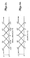
- Component 3 On-ramp Fuzzy Inference Engine (The on-ramp fuzzy sets are shown in FIGS. 4A, 4B, 4C, 4D, and 4E)
- This component receives decel, decel error, slope error, time, and nosedown as inputs, and calculates a value of ⁇ current (in 100,000ths of a mA).
- ⁇ current in 100,000ths of a mA.
- Component 4 Steady State Fuzzy Inference Engine (the steady state fuzzy sets are shown in FIGS. 5A and 5B where:
- This component receives decel error and slope as inputs, and calculates a value of ⁇ current (in 100,00ths of a mA).
- ⁇ current in 100,00ths of a mA.
- Component 5 Supervisory Mixing Component
- This component receives as inputs the ⁇ current from the On-ramp component, the ⁇ current from the Steady State Component, and the decel error, and calculates the ⁇ current by which the current will actually be increased.
- This calculation is a linear transition from On-ramp control to Steady State (S.S.) control as the decel error passes from less than -0.15 ms -2 to 0; i.e., ⁇ Current(out)
- the portion of control given to the S.S. component is held to a minimum of the highest value that it has attained so far. This means that the portion of control given to the S.S. component can never decrease, and that once the decel error reaches zero, all control will be from the S.S. component.
- Component 6 Summing and Limiting Component
- This component receives ⁇ current as an input, and calculates the current.
- the new current is equal to the previous current plus ⁇ current, limited to a minimum and maximum value.
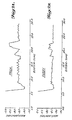
- FIGS. 7A and 7B show a comparison where the autobrake setting is 2.6 m/sec 2 deceleration with aircraft thrust reversers deployed.
- the present control logic is based on a set of rules which are vague, i.e. fuzzy.
- One example rule from the system is "If the Decel Error is Large Negative, and the Slope [Derivative of Decel Error] is Positive Small, then the ⁇ Current is Positive Very Small.”
- "Large Negative,” “Positive Small,” and “Positive Very Small” are defined by mathematical functions.
- the rule base is evaluated in parallel each decision cycle. First, a weight is assigned to each rule based on how applicable the rule is at the given point in time. The output is then calculated using these weights by taking the weighted average of all of the rules.
Landscapes
- Engineering & Computer Science (AREA)
- Mechanical Engineering (AREA)
- Transportation (AREA)
- Aviation & Aerospace Engineering (AREA)
- Physics & Mathematics (AREA)
- Fuzzy Systems (AREA)
- Mathematical Physics (AREA)
- Software Systems (AREA)
- Theoretical Computer Science (AREA)
- Feedback Control In General (AREA)
- Regulating Braking Force (AREA)
Claims (8)
- Système de freinage automatique pour avion pour générer un signal de commande de robinet de freinage sur la base d'une pluralité de signaux d'entrée, comprenant des entrées sélectionnées par le pilote prédéterminées ainsi que des signaux de tangage et de décélération de l'avion,
ledit système de freinage automatique étant caractérisé par :une pluralité de moteurs d'inférence de flou (2, 3, 4), chacun desdits moteurs d'inférence de flou (2, 3, 4) comprenant une pluralité de règles et de réglages de flou et étant sensible à un ensemble de signaux d'entrée choisis ou dérivés desdites entrées sélectionnées par le pilote prédéterminées et desdits signaux de tangage et de décélération de l'avion pour calculer un signal de sortie, etun composant de dosage de flou (5) sensible aux signaux de sortie en provenance de ladite pluralité de moteurs d'inférence de flou (2, 3, 4) pour générer un signal de commande de sortie. - Système de freinage automatique pour avion selon la revendication 1, dans lequel au moins un (3) desdits moteurs d'inférence de flou est sensible au signal de sortie d'au moins un (2) des autres moteurs d'inférence de flou.
- Système de freinage automatique pour avion selon la revendication 2, dans lequel le moteur d'inférence de flou (3) pour une commande de rampe est sensible au signal de sortie du moteur d'inférence de flou (2) pour une évaluation de piqué.
- Système de freinage automatique pour avion selon l'une quelconque des revendications précédentes, comprenant en outre :Un moyen de calcul (1) sensible auxdits signaux de tangage et de décélération de l'avion ainsi qu'auxdites entrées sélectionnées par le pilote prédéterminées, comprenant des entrées de pente de rampe pour générer des signaux représentatifs d'une erreur de décélération, de la pente, d'une erreur de pente et du temps,un premier moteur d'inférence de flou (2) sensible auxdits signaux de tangage et de temps pour générer un signal de sortie de piqué,un deuxième moteur d'inférence de flou (4) sensible auxdits signaux d'erreur de décélération et de pente pour générer un signal de sortie de commande de régime permanent,un troisième moteur d'inférence de flou (3) sensible auxdits signaux de décélération de l'avion, d'erreur de décélération, d'erreur de pente, de temps et de piqué pour générer un signal de sortie de commande de rampe, etun composant de dosage de flou (5) sensible audit signal de commande de rampe, audit signal de commande de régime permanent et audit signal d'erreur de décélération pour générer ledit signal de commande de sortie.
- Système de freinage automatique pour avion selon la revendication 4, dans lequel ledit signal de commande de sortie calculé par le moyen de dosage de flou (5) effectue une transition entre ledit signal de commande de rampe et ledit signal de commande de régime permanent lorsque l'erreur de décélération passe d'une valeur négative à zéro.
- Système de freinage automatique pour avion selon la revendication 5, dans lequel le poids relatif dudit signal de commande de régime permanent dans ledit signal de commande de sortie est toujours maintenu à un minimum de la valeur la plus élevée qu'il a atteint jusqu'à présent.
- Système de freinage automatique pour avion selon l'une quelconque des revendications 4 à 6, dans lequel ledit signal de commande de rampe, ledit signal de commande de régime permanent et ledit signal de commande de sortie en provenance dudit composant de dosage de flou (5) sont des signaux de courant incrémentiels en 100000èmes de mA.
- Système de freinage automatique pour avion selon la revendication 7, comprenant en outre un composant de sommation et de limitation (6) pour additionner les signaux de courant incrémentiels afin de générer ledit signal de commande de robinet de freinage limité à une valeur minimum et à une valeur maximum.
Applications Claiming Priority (2)
| Application Number | Priority Date | Filing Date | Title |
|---|---|---|---|
| US08/472,945 US5539642A (en) | 1993-05-21 | 1995-06-06 | Fuzzy logic autobrake system for aircraft |
| US472945 | 1999-12-27 |
Publications (4)
| Publication Number | Publication Date |
|---|---|
| EP0747276A2 EP0747276A2 (fr) | 1996-12-11 |
| EP0747276A3 EP0747276A3 (fr) | 1998-07-15 |
| EP0747276B1 EP0747276B1 (fr) | 2004-09-29 |
| EP0747276B2 true EP0747276B2 (fr) | 2009-12-09 |
Family
ID=23877533
Family Applications (1)
| Application Number | Title | Priority Date | Filing Date |
|---|---|---|---|
| EP96201088A Expired - Lifetime EP0747276B2 (fr) | 1995-06-06 | 1996-04-23 | Système automatique de freinage à logique floue pour avion |
Country Status (3)
| Country | Link |
|---|---|
| US (1) | US5539642A (fr) |
| EP (1) | EP0747276B2 (fr) |
| DE (1) | DE69633484T3 (fr) |
Families Citing this family (11)
| Publication number | Priority date | Publication date | Assignee | Title |
|---|---|---|---|---|
| US6088646A (en) * | 1996-10-25 | 2000-07-11 | The Boeing Company | Fuzzy logic antiskid control system for aircraft |
| US5968106A (en) * | 1997-08-05 | 1999-10-19 | The Boeing Company | Aircraft stop-to-position autobrake control system |
| US6510354B1 (en) * | 1999-04-21 | 2003-01-21 | Ching-Fang Lin | Universal robust filtering process |
| US6757569B2 (en) * | 2000-04-19 | 2004-06-29 | American Gnc Corporation | Filtering process for stable and accurate estimation |
| FR2857468B1 (fr) * | 2003-07-08 | 2005-09-30 | Airbus France | Systeme d'aide a la commande de la deceleration d'un aeronef roulant sur le sol |
| US7720579B2 (en) * | 2006-12-20 | 2010-05-18 | The Boeing Company | Method, system, and computer program product for performance monitored aircraft rejected takeoff braking |
| TR201613964A2 (tr) * | 2016-10-05 | 2016-11-21 | Selcuk Karaosmanoglu | Sifir ki̇li̇tlenme fren si̇stemi̇ |
| US10647306B2 (en) | 2018-04-23 | 2020-05-12 | Goodrich Corporation | Measurement of contact maintaining control valve current for a hydraulic actuator |
| FR3093993B1 (fr) * | 2019-03-21 | 2021-02-26 | Safran Aircraft Engines | Procédé de contrôle du freinage des roues d’un avion et contrôleur de freinage de roues associé |
| US11548625B2 (en) | 2019-12-13 | 2023-01-10 | Goodrich Corporation | Aircraft brake system |
| US12025994B2 (en) * | 2020-12-23 | 2024-07-02 | Rockwell Collins, Inc. | Rejected takeoff aircraft system and method |
Citations (1)
| Publication number | Priority date | Publication date | Assignee | Title |
|---|---|---|---|---|
| US4646242A (en) † | 1984-01-27 | 1987-02-24 | The Boeing Company | Aircraft automatic braking system |
Family Cites Families (18)
| Publication number | Priority date | Publication date | Assignee | Title |
|---|---|---|---|---|
| US4022513A (en) * | 1972-04-12 | 1977-05-10 | Crane Co., Hydro-Aire Division | Selective deceleration brake control system |
| US3920278A (en) * | 1973-08-30 | 1975-11-18 | Crane Co | Selective deceleration brake control system |
| US4076331A (en) * | 1973-09-06 | 1978-02-28 | The Boeing Company | Aircraft automatic braking system |
| US3926479A (en) * | 1973-11-12 | 1975-12-16 | Boeing Co | Aircraft automatic braking system having auto-brake control logic |
| US3920204A (en) * | 1974-11-11 | 1975-11-18 | Boeing Co | Rejected take-off (RTO) control for automatic braking system |
| US4007970A (en) * | 1975-09-30 | 1977-02-15 | The Boeing Company | Aircraft automatic braking system |
| US4327413A (en) * | 1979-09-12 | 1982-04-27 | Goodyear Aerospace Corporation | Automatic brake control circuit for aircraft |
| DE3231162C2 (de) * | 1982-08-21 | 1984-08-16 | Messerschmitt-Bölkow-Blohm GmbH, 8000 München | Verfahren für das beschleunigte Herbeiführen des Bodenkontaktes von Flugzeugen |
| US4610484A (en) * | 1983-09-23 | 1986-09-09 | The Boeing Company | Deceleration control brake system |
| JPH0698903B2 (ja) * | 1986-08-06 | 1994-12-07 | 本田技研工業株式会社 | 車両走行制御装置 |
| JP2681930B2 (ja) * | 1987-06-27 | 1997-11-26 | 株式会社デンソー | サーボ制御装置 |
| JPH01132450A (ja) * | 1987-11-17 | 1989-05-24 | Nissan Motor Co Ltd | アンチスキッドブレーキシステム |
| JP2536182B2 (ja) * | 1988-09-28 | 1996-09-18 | オムロン株式会社 | ファジイ・コントロ―ラ、ファジイ推論装置、ファジイル―ル管理装置、ファジイ・コントロ―ル方法、ファジイ推論方法及びファジイル―ル管理方法 |
| CN2044952U (zh) * | 1988-12-27 | 1989-09-27 | 青岛建筑工程学院 | 汽车气压应急制动装置 |
| US5136510A (en) * | 1990-02-20 | 1992-08-04 | Aircraft Braking Systems Corporation | Aircraft deceleration brake control system |
| JPH03258650A (ja) * | 1990-03-09 | 1991-11-18 | Toyota Motor Corp | 路面摩擦係数検出装置 |
| JP2668751B2 (ja) * | 1991-11-30 | 1997-10-27 | 三菱自動車工業株式会社 | 後輪制動力制御装置 |
| JP2855987B2 (ja) * | 1992-08-26 | 1999-02-10 | 三菱自動車工業株式会社 | アンチスキッドブレーキング方法 |
-
1995
- 1995-06-06 US US08/472,945 patent/US5539642A/en not_active Expired - Lifetime
-
1996
- 1996-04-23 EP EP96201088A patent/EP0747276B2/fr not_active Expired - Lifetime
- 1996-04-23 DE DE69633484T patent/DE69633484T3/de not_active Expired - Lifetime
Patent Citations (1)
| Publication number | Priority date | Publication date | Assignee | Title |
|---|---|---|---|---|
| US4646242A (en) † | 1984-01-27 | 1987-02-24 | The Boeing Company | Aircraft automatic braking system |
Non-Patent Citations (2)
| Title |
|---|
| CNRS: "Journée Nationale Commande Floue: Theorie, Methodologie, Application", 15 November 1991, ISBN: 1-99-51261/1, article A.TITLI: "Basic issues on fuzzy rules and their application to fuzzy control" † |
| TOSHIRO TERANO, KIYOJI ASAI AND MICHIO SUGENO: "Fuzzy systems theory and its applications", 1992, ACADEMIC PRESS LIMITED, LONDON, ISBN: 0-12-685245-6 † |
Also Published As
| Publication number | Publication date |
|---|---|
| EP0747276A2 (fr) | 1996-12-11 |
| EP0747276A3 (fr) | 1998-07-15 |
| EP0747276B1 (fr) | 2004-09-29 |
| DE69633484T2 (de) | 2005-11-17 |
| US5539642A (en) | 1996-07-23 |
| DE69633484T3 (de) | 2010-07-15 |
| DE69633484D1 (de) | 2004-11-04 |
Similar Documents
| Publication | Publication Date | Title |
|---|---|---|
| EP0747276B2 (fr) | Système automatique de freinage à logique floue pour avion | |
| EP0092832B1 (fr) | Méthode et dispositif pour arrêter un véhicule à une position déterminée | |
| US5571953A (en) | Method and apparatus for the linear real time estimation of an aircraft center of gravity | |
| JP4102166B2 (ja) | ロータトルク予測装置 | |
| Zhang et al. | Integrated design of reconfigurable fault-tolerant control systems | |
| JP4108450B2 (ja) | ロータトルク予測装置 | |
| US20020055809A1 (en) | Flight control system | |
| Kawamura et al. | A prototype of neuro-fuzzy cooperation system | |
| Duyar et al. | Fault detection and diagnosis in propulsion systems-A fault parameter estimation approach | |
| DE19537694A1 (de) | Verfahren zur Überwachung einer Maschine oder Anlage | |
| EP1429220B2 (fr) | Procédé et produit logiciel d'ordinateur pour la commande des gouvernes d'un véhicule aérodynamique | |
| Warnick et al. | A systematic antiwindup strategy and the longitudinal control of a platoon of vehicles with control saturations | |
| EP0742141B1 (fr) | Méthode et dispositif de génération d'une commande dynamique à la gouvernail pour la compensation d'une réaction asymétrique sans detection directe de cette réaction propulsive | |
| Vascak et al. | Performance-based adaptive fuzzy control of aircrafts | |
| US6131449A (en) | Velocity adaptive control test system | |
| Lea | Applications of fuzzy sets to rule-based expert system development | |
| Olson et al. | Model-follower longitudinal control for automated guideway transit vehicles | |
| Mulgund et al. | A hybrid neural network-fuzzy logic limit protection system for rotorcraft | |
| Berenji et al. | Pitch control of the space shuttle training aircraft | |
| Ursu et al. | An intelligent ABS control based on fuzzy logic. Aircraft application | |
| Ewers et al. | Expert supervision of an anti-skid control system of a commercial aircraft | |
| Attouche et al. | An efficient algorithm for the design of fault tolerant multi-sensor system | |
| Costea et al. | Automation and optimization of air traffic control systems | |
| Goebel | Decision forgetting and decision smoothing for diagnostic decision fusion in systems with redundant information | |
| Schram et al. | Fuzzy logic control |
Legal Events
| Date | Code | Title | Description |
|---|---|---|---|
| PUAI | Public reference made under article 153(3) epc to a published international application that has entered the european phase |
Free format text: ORIGINAL CODE: 0009012 |
|
| AK | Designated contracting states |
Kind code of ref document: A2 Designated state(s): DE FR GB |
|
| PUAL | Search report despatched |
Free format text: ORIGINAL CODE: 0009013 |
|
| AK | Designated contracting states |
Kind code of ref document: A3 Designated state(s): DE FR GB |
|
| 17P | Request for examination filed |
Effective date: 19981116 |
|
| 17Q | First examination report despatched |
Effective date: 20020705 |
|
| GRAP | Despatch of communication of intention to grant a patent |
Free format text: ORIGINAL CODE: EPIDOSNIGR1 |
|
| GRAS | Grant fee paid |
Free format text: ORIGINAL CODE: EPIDOSNIGR3 |
|
| GRAA | (expected) grant |
Free format text: ORIGINAL CODE: 0009210 |
|
| AK | Designated contracting states |
Kind code of ref document: B1 Designated state(s): DE FR GB |
|
| REG | Reference to a national code |
Ref country code: GB Ref legal event code: FG4D |
|
| REF | Corresponds to: |
Ref document number: 69633484 Country of ref document: DE Date of ref document: 20041104 Kind code of ref document: P |
|
| PLAQ | Examination of admissibility of opposition: information related to despatch of communication + time limit deleted |
Free format text: ORIGINAL CODE: EPIDOSDOPE2 |
|
| PLBI | Opposition filed |
Free format text: ORIGINAL CODE: 0009260 |
|
| PLBQ | Unpublished change to opponent data |
Free format text: ORIGINAL CODE: EPIDOS OPPO |
|
| PLAX | Notice of opposition and request to file observation + time limit sent |
Free format text: ORIGINAL CODE: EPIDOSNOBS2 |
|
| 26 | Opposition filed |
Opponent name: AIRBUS SAS Effective date: 20050628 |
|
| ET | Fr: translation filed | ||
| PLAF | Information modified related to communication of a notice of opposition and request to file observations + time limit |
Free format text: ORIGINAL CODE: EPIDOSCOBS2 |
|
| PLBB | Reply of patent proprietor to notice(s) of opposition received |
Free format text: ORIGINAL CODE: EPIDOSNOBS3 |
|
| APBM | Appeal reference recorded |
Free format text: ORIGINAL CODE: EPIDOSNREFNO |
|
| APBP | Date of receipt of notice of appeal recorded |
Free format text: ORIGINAL CODE: EPIDOSNNOA2O |
|
| APAH | Appeal reference modified |
Free format text: ORIGINAL CODE: EPIDOSCREFNO |
|
| APBU | Appeal procedure closed |
Free format text: ORIGINAL CODE: EPIDOSNNOA9O |
|
| RIC2 | Information provided on ipc code assigned after grant |
Ipc: B60T 8/17 20060101AFI20090803BHEP |
|
| PUAH | Patent maintained in amended form |
Free format text: ORIGINAL CODE: 0009272 |
|
| STAA | Information on the status of an ep patent application or granted ep patent |
Free format text: STATUS: PATENT MAINTAINED AS AMENDED |
|
| 27A | Patent maintained in amended form |
Effective date: 20091209 |
|
| AK | Designated contracting states |
Kind code of ref document: B2 Designated state(s): DE FR GB |
|
| REG | Reference to a national code |
Ref country code: FR Ref legal event code: PLFP Year of fee payment: 20 |
|
| PGFP | Annual fee paid to national office [announced via postgrant information from national office to epo] |
Ref country code: GB Payment date: 20150427 Year of fee payment: 20 Ref country code: DE Payment date: 20150429 Year of fee payment: 20 |
|
| PGFP | Annual fee paid to national office [announced via postgrant information from national office to epo] |
Ref country code: FR Payment date: 20150417 Year of fee payment: 20 |
|
| REG | Reference to a national code |
Ref country code: DE Ref legal event code: R071 Ref document number: 69633484 Country of ref document: DE |
|
| REG | Reference to a national code |
Ref country code: GB Ref legal event code: PE20 Expiry date: 20160422 |
|
| PG25 | Lapsed in a contracting state [announced via postgrant information from national office to epo] |
Ref country code: GB Free format text: LAPSE BECAUSE OF EXPIRATION OF PROTECTION Effective date: 20160422 |