EP0747310A2 - Corps cylindrique tournant avec faible inertie de masse - Google Patents
Corps cylindrique tournant avec faible inertie de masse Download PDFInfo
- Publication number
- EP0747310A2 EP0747310A2 EP96106889A EP96106889A EP0747310A2 EP 0747310 A2 EP0747310 A2 EP 0747310A2 EP 96106889 A EP96106889 A EP 96106889A EP 96106889 A EP96106889 A EP 96106889A EP 0747310 A2 EP0747310 A2 EP 0747310A2
- Authority
- EP
- European Patent Office
- Prior art keywords
- cylindrical body
- rotating cylindrical
- rotating
- body according
- inner cavity
- Prior art date
- Legal status (The legal status is an assumption and is not a legal conclusion. Google has not performed a legal analysis and makes no representation as to the accuracy of the status listed.)
- Granted
Links
Images


Classifications
-
- B—PERFORMING OPERATIONS; TRANSPORTING
- B29—WORKING OF PLASTICS; WORKING OF SUBSTANCES IN A PLASTIC STATE IN GENERAL
- B29C—SHAPING OR JOINING OF PLASTICS; SHAPING OF MATERIAL IN A PLASTIC STATE, NOT OTHERWISE PROVIDED FOR; AFTER-TREATMENT OF THE SHAPED PRODUCTS, e.g. REPAIRING
- B29C53/00—Shaping by bending, folding, twisting, straightening or flattening; Apparatus therefor
- B29C53/56—Winding and joining, e.g. winding spirally
- B29C53/58—Winding and joining, e.g. winding spirally helically
- B29C53/60—Winding and joining, e.g. winding spirally helically using internal forming surfaces, e.g. mandrels
- B29C53/62—Winding and joining, e.g. winding spirally helically using internal forming surfaces, e.g. mandrels rotatable about the winding axis
- B29C53/66—Winding and joining, e.g. winding spirally helically using internal forming surfaces, e.g. mandrels rotatable about the winding axis with axially movable winding feed member, e.g. lathe type winding
-
- B—PERFORMING OPERATIONS; TRANSPORTING
- B65—CONVEYING; PACKING; STORING; HANDLING THIN OR FILAMENTARY MATERIAL
- B65H—HANDLING THIN OR FILAMENTARY MATERIAL, e.g. SHEETS, WEBS, CABLES
- B65H27/00—Special constructions, e.g. surface features, of feed or guide rollers for webs
-
- F—MECHANICAL ENGINEERING; LIGHTING; HEATING; WEAPONS; BLASTING
- F16—ENGINEERING ELEMENTS AND UNITS; GENERAL MEASURES FOR PRODUCING AND MAINTAINING EFFECTIVE FUNCTIONING OF MACHINES OR INSTALLATIONS; THERMAL INSULATION IN GENERAL
- F16C—SHAFTS; FLEXIBLE SHAFTS; ELEMENTS OR CRANKSHAFT MECHANISMS; ROTARY BODIES OTHER THAN GEARING ELEMENTS; BEARINGS
- F16C13/00—Rolls, drums, discs, or the like; Bearings or mountings therefor
-
- B—PERFORMING OPERATIONS; TRANSPORTING
- B29—WORKING OF PLASTICS; WORKING OF SUBSTANCES IN A PLASTIC STATE IN GENERAL
- B29C—SHAPING OR JOINING OF PLASTICS; SHAPING OF MATERIAL IN A PLASTIC STATE, NOT OTHERWISE PROVIDED FOR; AFTER-TREATMENT OF THE SHAPED PRODUCTS, e.g. REPAIRING
- B29C53/00—Shaping by bending, folding, twisting, straightening or flattening; Apparatus therefor
- B29C53/80—Component parts, details or accessories; Auxiliary operations
- B29C53/8008—Component parts, details or accessories; Auxiliary operations specially adapted for winding and joining
- B29C53/805—Applying axial reinforcements
-
- B—PERFORMING OPERATIONS; TRANSPORTING
- B29—WORKING OF PLASTICS; WORKING OF SUBSTANCES IN A PLASTIC STATE IN GENERAL
- B29L—INDEXING SCHEME ASSOCIATED WITH SUBCLASS B29C, RELATING TO PARTICULAR ARTICLES
- B29L2031/00—Other particular articles
- B29L2031/32—Wheels, pinions, pulleys, castors or rollers, Rims
- B29L2031/324—Rollers or cylinders having an axial length of several times the diameter, e.g. embossing, pressing or printing
-
- B—PERFORMING OPERATIONS; TRANSPORTING
- B65—CONVEYING; PACKING; STORING; HANDLING THIN OR FILAMENTARY MATERIAL
- B65H—HANDLING THIN OR FILAMENTARY MATERIAL, e.g. SHEETS, WEBS, CABLES
- B65H2404/00—Parts for transporting or guiding the handled material
- B65H2404/10—Rollers
- B65H2404/13—Details of longitudinal profile
- B65H2404/132—Details of longitudinal profile arrangement of segments along axis
- B65H2404/1321—Segments juxtaposed along axis
-
- B—PERFORMING OPERATIONS; TRANSPORTING
- B65—CONVEYING; PACKING; STORING; HANDLING THIN OR FILAMENTARY MATERIAL
- B65H—HANDLING THIN OR FILAMENTARY MATERIAL, e.g. SHEETS, WEBS, CABLES
- B65H2404/00—Parts for transporting or guiding the handled material
- B65H2404/10—Rollers
- B65H2404/14—Roller pairs
- B65H2404/145—Roller pairs other
- B65H2404/1451—Pressure
-
- B—PERFORMING OPERATIONS; TRANSPORTING
- B65—CONVEYING; PACKING; STORING; HANDLING THIN OR FILAMENTARY MATERIAL
- B65H—HANDLING THIN OR FILAMENTARY MATERIAL, e.g. SHEETS, WEBS, CABLES
- B65H2404/00—Parts for transporting or guiding the handled material
- B65H2404/10—Rollers
- B65H2404/17—Details of bearings
- B65H2404/171—Details of bearings beam supply
-
- B—PERFORMING OPERATIONS; TRANSPORTING
- B65—CONVEYING; PACKING; STORING; HANDLING THIN OR FILAMENTARY MATERIAL
- B65H—HANDLING THIN OR FILAMENTARY MATERIAL, e.g. SHEETS, WEBS, CABLES
- B65H2404/00—Parts for transporting or guiding the handled material
- B65H2404/10—Rollers
- B65H2404/18—Rollers composed of several layers
- B65H2404/183—Rollers composed of several layers with outer layer helicoidally turned around shaft
-
- B—PERFORMING OPERATIONS; TRANSPORTING
- B65—CONVEYING; PACKING; STORING; HANDLING THIN OR FILAMENTARY MATERIAL
- B65H—HANDLING THIN OR FILAMENTARY MATERIAL, e.g. SHEETS, WEBS, CABLES
- B65H2404/00—Parts for transporting or guiding the handled material
- B65H2404/10—Rollers
- B65H2404/18—Rollers composed of several layers
- B65H2404/183—Rollers composed of several layers with outer layer helicoidally turned around shaft
- B65H2404/1831—Rollers composed of several layers with outer layer helicoidally turned around shaft wire around shaft
-
- Y—GENERAL TAGGING OF NEW TECHNOLOGICAL DEVELOPMENTS; GENERAL TAGGING OF CROSS-SECTIONAL TECHNOLOGIES SPANNING OVER SEVERAL SECTIONS OF THE IPC; TECHNICAL SUBJECTS COVERED BY FORMER USPC CROSS-REFERENCE ART COLLECTIONS [XRACs] AND DIGESTS
- Y10—TECHNICAL SUBJECTS COVERED BY FORMER USPC
- Y10T—TECHNICAL SUBJECTS COVERED BY FORMER US CLASSIFICATION
- Y10T428/00—Stock material or miscellaneous articles
- Y10T428/13—Hollow or container type article [e.g., tube, vase, etc.]
- Y10T428/131—Glass, ceramic, or sintered, fused, fired, or calcined metal oxide or metal carbide containing [e.g., porcelain, brick, cement, etc.]
- Y10T428/1314—Contains fabric, fiber particle, or filament made of glass, ceramic, or sintered, fused, fired, or calcined metal oxide, or metal carbide or other inorganic compound [e.g., fiber glass, mineral fiber, sand, etc.]
-
- Y—GENERAL TAGGING OF NEW TECHNOLOGICAL DEVELOPMENTS; GENERAL TAGGING OF CROSS-SECTIONAL TECHNOLOGIES SPANNING OVER SEVERAL SECTIONS OF THE IPC; TECHNICAL SUBJECTS COVERED BY FORMER USPC CROSS-REFERENCE ART COLLECTIONS [XRACs] AND DIGESTS
- Y10—TECHNICAL SUBJECTS COVERED BY FORMER USPC
- Y10T—TECHNICAL SUBJECTS COVERED BY FORMER US CLASSIFICATION
- Y10T428/00—Stock material or miscellaneous articles
- Y10T428/13—Hollow or container type article [e.g., tube, vase, etc.]
- Y10T428/1334—Nonself-supporting tubular film or bag [e.g., pouch, envelope, packet, etc.]
- Y10T428/1341—Contains vapor or gas barrier, polymer derived from vinyl chloride or vinylidene chloride, or polymer containing a vinyl alcohol unit
-
- Y—GENERAL TAGGING OF NEW TECHNOLOGICAL DEVELOPMENTS; GENERAL TAGGING OF CROSS-SECTIONAL TECHNOLOGIES SPANNING OVER SEVERAL SECTIONS OF THE IPC; TECHNICAL SUBJECTS COVERED BY FORMER USPC CROSS-REFERENCE ART COLLECTIONS [XRACs] AND DIGESTS
- Y10—TECHNICAL SUBJECTS COVERED BY FORMER USPC
- Y10T—TECHNICAL SUBJECTS COVERED BY FORMER US CLASSIFICATION
- Y10T428/00—Stock material or miscellaneous articles
- Y10T428/13—Hollow or container type article [e.g., tube, vase, etc.]
- Y10T428/1352—Polymer or resin containing [i.e., natural or synthetic]
-
- Y—GENERAL TAGGING OF NEW TECHNOLOGICAL DEVELOPMENTS; GENERAL TAGGING OF CROSS-SECTIONAL TECHNOLOGIES SPANNING OVER SEVERAL SECTIONS OF THE IPC; TECHNICAL SUBJECTS COVERED BY FORMER USPC CROSS-REFERENCE ART COLLECTIONS [XRACs] AND DIGESTS
- Y10—TECHNICAL SUBJECTS COVERED BY FORMER USPC
- Y10T—TECHNICAL SUBJECTS COVERED BY FORMER US CLASSIFICATION
- Y10T428/00—Stock material or miscellaneous articles
- Y10T428/13—Hollow or container type article [e.g., tube, vase, etc.]
- Y10T428/1352—Polymer or resin containing [i.e., natural or synthetic]
- Y10T428/1355—Elemental metal containing [e.g., substrate, foil, film, coating, etc.]
-
- Y—GENERAL TAGGING OF NEW TECHNOLOGICAL DEVELOPMENTS; GENERAL TAGGING OF CROSS-SECTIONAL TECHNOLOGIES SPANNING OVER SEVERAL SECTIONS OF THE IPC; TECHNICAL SUBJECTS COVERED BY FORMER USPC CROSS-REFERENCE ART COLLECTIONS [XRACs] AND DIGESTS
- Y10—TECHNICAL SUBJECTS COVERED BY FORMER USPC
- Y10T—TECHNICAL SUBJECTS COVERED BY FORMER US CLASSIFICATION
- Y10T428/00—Stock material or miscellaneous articles
- Y10T428/13—Hollow or container type article [e.g., tube, vase, etc.]
- Y10T428/1352—Polymer or resin containing [i.e., natural or synthetic]
- Y10T428/1362—Textile, fabric, cloth, or pile containing [e.g., web, net, woven, knitted, mesh, nonwoven, matted, etc.]
-
- Y—GENERAL TAGGING OF NEW TECHNOLOGICAL DEVELOPMENTS; GENERAL TAGGING OF CROSS-SECTIONAL TECHNOLOGIES SPANNING OVER SEVERAL SECTIONS OF THE IPC; TECHNICAL SUBJECTS COVERED BY FORMER USPC CROSS-REFERENCE ART COLLECTIONS [XRACs] AND DIGESTS
- Y10—TECHNICAL SUBJECTS COVERED BY FORMER USPC
- Y10T—TECHNICAL SUBJECTS COVERED BY FORMER US CLASSIFICATION
- Y10T428/00—Stock material or miscellaneous articles
- Y10T428/13—Hollow or container type article [e.g., tube, vase, etc.]
- Y10T428/1352—Polymer or resin containing [i.e., natural or synthetic]
- Y10T428/1379—Contains vapor or gas barrier, polymer derived from vinyl chloride or vinylidene chloride, or polymer containing a vinyl alcohol unit
-
- Y—GENERAL TAGGING OF NEW TECHNOLOGICAL DEVELOPMENTS; GENERAL TAGGING OF CROSS-SECTIONAL TECHNOLOGIES SPANNING OVER SEVERAL SECTIONS OF THE IPC; TECHNICAL SUBJECTS COVERED BY FORMER USPC CROSS-REFERENCE ART COLLECTIONS [XRACs] AND DIGESTS
- Y10—TECHNICAL SUBJECTS COVERED BY FORMER USPC
- Y10T—TECHNICAL SUBJECTS COVERED BY FORMER US CLASSIFICATION
- Y10T428/00—Stock material or miscellaneous articles
- Y10T428/13—Hollow or container type article [e.g., tube, vase, etc.]
- Y10T428/1352—Polymer or resin containing [i.e., natural or synthetic]
- Y10T428/139—Open-ended, self-supporting conduit, cylinder, or tube-type article
-
- Y—GENERAL TAGGING OF NEW TECHNOLOGICAL DEVELOPMENTS; GENERAL TAGGING OF CROSS-SECTIONAL TECHNOLOGIES SPANNING OVER SEVERAL SECTIONS OF THE IPC; TECHNICAL SUBJECTS COVERED BY FORMER USPC CROSS-REFERENCE ART COLLECTIONS [XRACs] AND DIGESTS
- Y10—TECHNICAL SUBJECTS COVERED BY FORMER USPC
- Y10T—TECHNICAL SUBJECTS COVERED BY FORMER US CLASSIFICATION
- Y10T442/00—Fabric [woven, knitted, or nonwoven textile or cloth, etc.]
- Y10T442/10—Scrim [e.g., open net or mesh, gauze, loose or open weave or knit, etc.]
- Y10T442/102—Woven scrim
- Y10T442/172—Coated or impregnated
Definitions
- the present invention relates to a rotating cylindrical body with low inertia, in particular for use in rotary printing machines.
- US 4,903,597 describes printing plate sleeves and methods for mounting and dismounting the same.
- An endless, cylindrical pressure plate sleeve is provided, which can be easily attached and removed axially in a complementary cylindrical pressure cylinder.
- the pressure cylinder is hollow and its interior serves as a compressed air chamber.
- the cylinder has a cylindrical tube with airtight end plates. A plurality of spaced apart, radially extending openings are provided in the tube through which air can flow from the chamber to expand the sleeve during mounting and removal.
- EP 0 451 890 A1 discloses a roller and a method for producing the roller.
- a cylindrical metal roller housing is centered with respect to the roller axis.
- the housing, a thin electrolytic molded sleeve, is centered by journals and a low density filler is introduced into the housing.
- the low density filler gives the roller case i.e. the electrolytically shaped socket, rigidity.
- a rotating cylindrical body with low mass inertia comprises a cylindrical body with a large length / diameter ratio, the cylindrical body being made of a composite material with a small wall thickness.
- the inner cavity of the cylindrical body is sealed by caps and filled with a pressure medium.
- the cylindrical body and the sealing caps can consist of a layered composite material.
- the caps can be made of metal, such as aluminum.
- the cylindrical body and the Caps include reinforcement elements.
- the caps for example, can have annular elements which are inserted into the inner cavity of the cylindrical body.
- Another reinforcing means is a pretensioning or compression pretensioning rod that spans the inner cavity of the cylindrical body to improve flexural rigidity.
- the biasing or compression biasing rod preferably passes through a center line of the cylindrical body. Annular elements distributed across the width of the cylindrical body can also be used to improve flexural rigidity.
- the cylindrical surface of the cylindrical body can have a groove pattern with an angular offset against the center line of the cylindrical body.
- the groove pattern enables the removal of an air bearing or air film between the web of material and the roller or roller surface.
- the composite material can be formed with strands of fiberglass or other material with an angular orientation of 45 ° to the center line, starting from each cylinder end. It is also possible to reinforce the composite material with prestressed longitudinal strands or fibers to improve the bending stiffness of the cylindrical body.
- the composite material can consist, for example, of a layered material or fiberglass. Furthermore, it is conceivable to enclose a carbon-filled or carbon-containing layer or layer within a layered structure of the composite material.
- the layered composite can include, for example, strands, threads, cords, fabrics, braid, wires, cylinders, or resins.
- the composite materials can be laminated glass fiber or fiberglass strands between resin layers.
- epoxy resin or polyester resin can be used as the resin.
- the strands can also consist of carbon fibers and / or graphite instead of glass.
- the composite material can consist of winding cords embedded in resin.
- the cords can be fiberglass, carbon fiber and / or graphite cords.
- the composite material can also consist of a metal cylinder laminated between resin layers.
- the inner cavity of the cylindrical body can be pressurized with gas, foam, liquid or a liquid mixture.
- Usable gases are, for example, air, carbon dioxide, helium or some other non-flammable gas.
- Usable foams are, for example, expansion foams and structural foams.
- Useful liquids are, for example, water, oils, coolants, etc., and examples of useful liquid mixtures are water / glycol, water / oil and oil / oil mixtures.
- the rotating cylindrical body according to the present invention can be manufactured by winding a first strand of fibrous material around a cylindrical body from a first end of the cylindrical body at an angle of approximately 45 ° with respect to a center line of the cylindrical body; Winding a second strand of fibrous material around a cylindrical body from a second end of the cylindrical body at an angle of approximately 45 ° with respect to a center line of the cylindrical body to achieve a cross pattern with the first strand; Mount a cap on each end of the cylindrical body to seal the inner cavity of the cylindrical body and fill a pressure medium into the inner cavity of the cylindrical body.
- Fig. 1 shows a rotating cylindrical body according to the present invention, which includes a thin-walled cylinder with caps with trunnions.
- a cylindrical body 1 has a cylindrical surface 2.
- Caps 3 are arranged at the opposite ends of the cylindrical body 1.
- the caps 3 have journals 5 and each have medium channels 7 for connecting the inner cavity 9 of the cylindrical body 1 to a medium source (not shown).
- a medium 10 can be, for example, a gas to be compressed in the inner cavity 9 of the cylindrical body 1 or a foam.
- a liquid or a liquid mixture can also be passed through the channels 7 into the inner cavity 9.
- Useful gases are, for example, air, carbon dioxide, helium or some other non-flammable gas.
- Usable foams are, for example, expansion foams and structural foams. Examples of usable liquids are water, oils, coolants etc., and examples of useful liquid mixtures are water / glycol, water / oil and oil / oil mixtures.
- the sealing caps 3 each contain reinforcement parts 4.
- the reinforcement parts 4 are constructed in a ring shape and serve to stiffen the outer ends of the cylindrical body 1.
- the bending stiffness of the cylindrical body 1 is considerably improved by filling the inner cavity 9 with a pressure medium 10 .
- the pressurization of the cylindrical body 1 results in a preload of the cylindrical body 1, which increases the resistance to bending loads and counteracts the buckling and buckling of the thin walls of the cylindrical body 1.
- the ratio between the radius of the cylindrical body 1 and the walls of the cylindrical body 1 is equal to or greater than 10: 1.
- the inertia of the cylindrical body is reduced while maintaining sufficient rigidity by reducing its mass.
- the reduction in the mass of the cylindrical body 1 also means a considerable reduction in the manufacturing costs.
- the cylindrical body 1 consists of a composite material. This means that if the rotating cylindrical body 1 fails, only a crack occurs in the cylinder surface 2. In contrast, failure of a pressurized metallic cylindrical body can cause metal particles to chip off and be thrown into the work space. This means that the use of a composite material prevents injuries to operators and damage to machine parts in a printing unit.
- the rotating cylindrical body according to the present invention can be used in printing machines. It is suitable, for example, for use in a splicing unit or in a web feed unit with a (meander) memory. Further Possible applications are in chill roll stands, a turning bar arrangement, a folder or a displacement and cutting unit.
- the rotating cylindrical body 1 according to the present invention can be used, for example, as an adjustable cutting cylinder in folders or for varying the tension.
- the present invention can be used in a cooling roll stand if a liquid or a liquid mixture such as water, water / glycol, water / alcohol, oils or coolants is used to act on the inner cavity 9 of the cylindrical body 1.
- Fig. 1 shows that the caps 3 have annular reinforcements 4 which are inserted into the inner cavity 9 of the cylindrical body 1 at its opposite ends.
- annular stiffening parts 15 can be provided in the inner cavity 9 over the width of the cylindrical body 1. These stiffening parts 15 considerably improve the rigidity of the structure and are arranged at a distance from one another over the length of the cylindrical body 1.
- the same purpose - the improvement of the bending stiffness of the cylindrical body - can be achieved by filling the inner cavity 9 of the cylindrical body 1 with a foam.
- the channels 7 for the medium 10 can be provided with a filling valve or a sealing plug for sealing the inner cavity 9 of the cylindrical body from the environment.
- Fig. 2 shows a further embodiment of the present invention, in which the caps are provided with a hub.
- the air channels are the same as those provided in Fig. 1.
- the caps 8 have the same reinforcement parts 4 as described in Fig. 1. They are equipped with a sealing device 6, which can be, for example, a filling valve or a closure stop.
- Reference number 13 denotes a liquid which is applied to the inner cavity 9 of the cylindrical body 1 in the second embodiment.
- the groove pattern 160 can be formed on the circumference of the cylindrical body at an angle of 45 ° to the center line. This groove pattern 160 eliminates air bearings or air films between a web of material and the surface of a roll.
- a longitudinal pretensioning or pressure pretensioning rod 11, as shown in FIG. 2, can also be provided. Its connection to the caps 8 is shown only schematically.
- the rod 11 in the same way by screwing the rod 11 into the caps, by connecting the rod 11 to the caps with pins, by gluing the rod 11 to the caps, by welding the rod 11 to the caps or on any other suitable type can be connected to the caps.
- the rod 11 is screwed to the closure caps by nuts screwed onto the rod, the rod ends protrude outward through the air duct beyond the closure caps.
- the pretensioning or pressure pretensioning rod 11 extends through the center line of the cylindrical body 1. It improves the bending stiffness of the cylindrical body 1.
- the pretensioning or pressure pretensioning rod 11 can be made of any suitable material, for example steel.
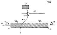
- the rigidity of the cylindrical body can be improved by winding the body with strands 16 made of fiberglass or other fiber material in a cross shape at angles of 45 ° to the center line 60. Wrapping begins from each end of the cylindrical body to increase its flexural strength.
- the strands are wound using conventional winding methods.
- a feed spool 21 carries wound strands 16.
- the strand 16 is fed to a guide rod 23 via a guide 22.
- the cylindrical body 1 is on one Device (not shown) rotatably attached.
- the strand 16 is drawn off from the feed reel 21 via the guide 22 and chemically bonded to the cylindrical body, for example with resin.
- the guide 22 is moved axially along the guide rod 23 at such a speed that there is a 45 ° angle around the rotating cylindrical body 1.
- longitudinal strands 50 of fiberglass or other fiber material e.g. Carbon fibers, which are kept under tension during the manufacture of the cylindrical body, are used to improve the flexural strength against acting loads.
- the longitudinal strands 50 can be attached by any suitable method.
- the longitudinal strands 50 can be attached to rings at each end of the cylinder 1, for example. Thereafter, the rings can be pulled during manufacture so that the longitudinal strands 50 are kept under tension during the manufacturing process.
- each longitudinal strand 50 can be connected to winding drums or winding cylinders (similar to the procedure for assembling guitar strings) and can be held taut during manufacture.
- the longitudinal strands 50 under the winding layers 16.1, 16.2, as shown in FIG. 4 (b), can be between two winding layers 16.1. 16.2 as shown in Fig. 4 (c) or over the winding layers 16.1, 16.2 as shown in Fig. 4 (d).
Landscapes
- Engineering & Computer Science (AREA)
- Mechanical Engineering (AREA)
- General Engineering & Computer Science (AREA)
- Moulding By Coating Moulds (AREA)
- Rotary Presses (AREA)
- Registering, Tensioning, Guiding Webs, And Rollers Therefor (AREA)
- Rolls And Other Rotary Bodies (AREA)
Applications Claiming Priority (2)
| Application Number | Priority Date | Filing Date | Title |
|---|---|---|---|
| US46249695A | 1995-06-05 | 1995-06-05 | |
| US462496 | 1995-06-05 |
Publications (3)
| Publication Number | Publication Date |
|---|---|
| EP0747310A2 true EP0747310A2 (fr) | 1996-12-11 |
| EP0747310A3 EP0747310A3 (fr) | 1997-11-05 |
| EP0747310B1 EP0747310B1 (fr) | 1999-01-20 |
Family
ID=23836631
Family Applications (1)
| Application Number | Title | Priority Date | Filing Date |
|---|---|---|---|
| EP19960106889 Expired - Lifetime EP0747310B1 (fr) | 1995-06-05 | 1996-05-02 | Corps cylindrique tournant avec faible inertie de masse |
Country Status (5)
| Country | Link |
|---|---|
| US (1) | US6086969A (fr) |
| EP (1) | EP0747310B1 (fr) |
| JP (1) | JP3031623U (fr) |
| CA (1) | CA2178236A1 (fr) |
| DE (2) | DE19616756A1 (fr) |
Cited By (3)
| Publication number | Priority date | Publication date | Assignee | Title |
|---|---|---|---|---|
| FR2764277A1 (fr) * | 1997-06-06 | 1998-12-11 | Alain Boyer | Cylindre rotatif a faible inertie de masse |
| FR2774025A1 (fr) * | 1998-01-26 | 1999-07-30 | Roland Man Druckmasch | Dispositif de refroidissement dans une installation de pliage et procede de refroidissement |
| EP0953532A3 (fr) * | 1998-05-01 | 2000-03-22 | Heidelberger Druckmaschinen Aktiengesellschaft | Dispositif pour éviter la salissure pendant le transport d'un bande imprimée |
Families Citing this family (7)
| Publication number | Priority date | Publication date | Assignee | Title |
|---|---|---|---|---|
| DE19807712C2 (de) * | 1998-02-24 | 2002-04-18 | Freudenberg Carl Kg | Verfahren zur Herstellung einer Oberflächenpanzerung auf einer Walze und Vorrichtung hierfür |
| DE19811397C1 (de) * | 1998-03-16 | 1999-11-11 | Deutsch Zentr Luft & Raumfahrt | Vorrichtung zur Belegung eines Werkstückes mit einer mit Matrixmaterial beschichteten spröden Endlosfaser |
| DE10153693B4 (de) * | 2001-10-31 | 2004-03-04 | Xperion Gmbh | Walze |
| DE10305699A1 (de) * | 2003-02-12 | 2004-08-26 | Kampf Gmbh & Co Maschinenfabrik | Walze für eine Wickelmaschine |
| US20070119319A1 (en) * | 2004-01-15 | 2007-05-31 | Weber Jan T | Cylinder for receiving a printing form |
| DE102006057853B3 (de) * | 2006-12-08 | 2008-06-12 | Xperion Gmbh | Biegewalze |
| JP5275051B2 (ja) * | 2009-01-07 | 2013-08-28 | 三菱重工マシナリーテクノロジー株式会社 | タイヤユニフォーミティマシン |
Family Cites Families (17)
| Publication number | Priority date | Publication date | Assignee | Title |
|---|---|---|---|---|
| DE124788C (fr) * | ||||
| US3654050A (en) * | 1969-10-06 | 1972-04-04 | Hughes Aircraft Co | Fabricated structure of improved expandable dimensional precision and method |
| GB1430286A (en) * | 1973-01-31 | 1976-03-31 | Vetroresina Spa | Method and apparatus for manufacturing pipes |
| NL178443C (nl) * | 1975-12-02 | 1986-03-17 | Brugman Machinefabriek Bv | Geleidingsrol. |
| DD124788A1 (fr) * | 1976-04-05 | 1977-03-16 | ||
| CH643796A5 (de) * | 1980-04-11 | 1984-06-29 | Sig Schweiz Industrieges | Umlenkrolle fuer bahnfoermiges, blattartiges material. |
| GB8312384D0 (en) * | 1983-05-05 | 1983-06-08 | Drg Uk Ltd | Printing roll with detachable sleeve |
| JPS61155154A (ja) * | 1984-12-28 | 1986-07-14 | Toshiba Corp | ロ−ラ |
| US4903597A (en) * | 1988-10-24 | 1990-02-27 | Lavalley Industries, Inc. | Printing sleeves and methods for mounting and dismounting |
| GB8925103D0 (en) * | 1989-11-07 | 1989-12-28 | Courtaulds Plc | Improved roller |
| NL9000645A (nl) * | 1990-03-20 | 1991-10-16 | Stork Screens Bv | Werkwijze voor het vervaardigen van een wals en aldus verkregen wals. |
| US5665441A (en) * | 1991-10-29 | 1997-09-09 | Daiwa Seiko, Inc. | Hollow cylindricall member |
| US5324246A (en) * | 1993-01-13 | 1994-06-28 | Greenmaster Industrial Corporation | Multi-purpose physical exercising machine |
| DE9305806U1 (de) * | 1993-04-19 | 1993-06-09 | Hoechst Ag, 6230 Frankfurt | Druckwalze mit einer Hülse aus thermisch gewickelten faserverstärkten Thermoplasten und einer plasmagespritzten Kupfer- oder Kupferlegierungsbeschichtung |
| US5402721A (en) * | 1993-05-13 | 1995-04-04 | Comco Machinery, Inc. | Vacuum printing plate roller |
| DE4418549A1 (de) * | 1993-06-02 | 1994-12-08 | Barmag Barmer Maschf | Drehbar gelagerte Walze |
| DE9314568U1 (de) * | 1993-09-27 | 1995-02-02 | Eduard Küsters Maschinenfabrik GmbH & Co KG, 47805 Krefeld | Walze |
-
1996
- 1996-04-26 DE DE1996116756 patent/DE19616756A1/de not_active Withdrawn
- 1996-05-02 EP EP19960106889 patent/EP0747310B1/fr not_active Expired - Lifetime
- 1996-05-02 DE DE59601169T patent/DE59601169D1/de not_active Expired - Lifetime
- 1996-05-24 JP JP1996004542U patent/JP3031623U/ja not_active Expired - Lifetime
- 1996-06-05 CA CA 2178236 patent/CA2178236A1/fr not_active Abandoned
-
1997
- 1997-03-31 US US08/831,455 patent/US6086969A/en not_active Expired - Fee Related
Cited By (4)
| Publication number | Priority date | Publication date | Assignee | Title |
|---|---|---|---|---|
| FR2764277A1 (fr) * | 1997-06-06 | 1998-12-11 | Alain Boyer | Cylindre rotatif a faible inertie de masse |
| FR2774025A1 (fr) * | 1998-01-26 | 1999-07-30 | Roland Man Druckmasch | Dispositif de refroidissement dans une installation de pliage et procede de refroidissement |
| US6109184A (en) * | 1998-01-26 | 2000-08-29 | Man Roland Druckmaschinen Ag | Cooling arrangement in a folding assembly and cooling process |
| EP0953532A3 (fr) * | 1998-05-01 | 2000-03-22 | Heidelberger Druckmaschinen Aktiengesellschaft | Dispositif pour éviter la salissure pendant le transport d'un bande imprimée |
Also Published As
| Publication number | Publication date |
|---|---|
| US6086969A (en) | 2000-07-11 |
| CA2178236A1 (fr) | 1996-12-06 |
| EP0747310A3 (fr) | 1997-11-05 |
| JP3031623U (ja) | 1996-11-29 |
| EP0747310B1 (fr) | 1999-01-20 |
| DE59601169D1 (de) | 1999-03-04 |
| DE19616756A1 (de) | 1996-12-12 |
Similar Documents
| Publication | Publication Date | Title |
|---|---|---|
| DE69601431T2 (de) | Eine konzentrische Hülse für einen Rotationsdruckzylinder | |
| EP0819550B1 (fr) | Manchon à base de caoutchouc pour machines rotatives offset | |
| DE10345159B4 (de) | Hochdrucktank, der hochsteife Fasern verwendet, und Verfahren zum Herstellen desselben | |
| EP1025996B1 (fr) | Cylindre porte-plaque | |
| DE102005053245A1 (de) | Druckbehälter, Wasserstoffspeichertank und Verfahren zum Herstellen des Druckbehälters | |
| EP0747310B1 (fr) | Corps cylindrique tournant avec faible inertie de masse | |
| DE2739579A1 (de) | Verfahren zur herstellung faserverstaerkter hohlkoerper | |
| DE102018210788A1 (de) | Herstellungsverfahren für einen faserverstärkten Behälter | |
| DE102018121843B4 (de) | Tankherstellungsverfahren umfassend das Wickeln einer mit Harz imprägnierten Faserbahn und Tank hergestellt durch das Tankherstellungsverfahren | |
| DE112022006187T5 (de) | Kohlenstofffaser-fixier-einspannvorrichtung, verfahren zur herstellung eines kohlenstofffaserverstärkten harzrohrkörpers, und kraftübertragungswelle | |
| DE102008041268A1 (de) | Walze für Auftragseinrichtung und Verfahren zum Auswuchten einer Walze | |
| DE3822417C2 (fr) | ||
| DE69208292T2 (de) | Verbesserungen an Begrenzerringen der elastischen Lager und des Verfahrens zu ihrer Herstellung | |
| EP3142843B1 (fr) | Procédé de production d'un tube d'amortisseur à partir d'un matériau composite renforcé par des fibres pour amortisseur de vibrations | |
| DE102019212155B4 (de) | Röhrenförmiger Drucktank zur Speicherung von Brennstoff in einem Kraftfahrzeug und Herstellverfahren | |
| DE102017211419A1 (de) | Verfahren zur Herstellung eines faserverstärkten Bauteils für ein Kraftfahrzeug und faserverstärktes Bauteil | |
| EP1967360B1 (fr) | Manchon et outil de serrage destinés à l'utilisation dans un système constitué d'un outil de serrage et d'au moins un manchon | |
| DE102017219380B4 (de) | Verfahren zur Herstellung eines Druckbehälters | |
| DE102023102709A1 (de) | Verfahren zur Herstellung einer Polkappenverstärkung für einen Druckbehälter sowie Druckbehälter mit Polkappenverstärkung | |
| DE29613795U1 (de) | Walze mit optimiertem Biegeverhalten | |
| WO2019185369A1 (fr) | Récipient sous pression ainsi que procédé de fabrication d'une enveloppe extérieure pour un récipient sous pression | |
| DE4435856C1 (de) | Verfahren zum Herstellen von Faserverbundrohren mit äußerer, metallischer Oberfläche und Vorrichtung zum Durchführen des Verfahrens | |
| DE102018204805A1 (de) | Druckbehälter sowie Verfahren zur Anbindung eines Druckbehälters in eine Karosseriestruktur | |
| WO2005067364A2 (fr) | Cylindre pour recevoir une forme d'impression | |
| EP0390300A1 (fr) | Procédé pour la fabrication d'un corps de roue |
Legal Events
| Date | Code | Title | Description |
|---|---|---|---|
| PUAI | Public reference made under article 153(3) epc to a published international application that has entered the european phase |
Free format text: ORIGINAL CODE: 0009012 |
|
| 17P | Request for examination filed |
Effective date: 19960502 |
|
| AK | Designated contracting states |
Kind code of ref document: A2 Designated state(s): DE FR GB |
|
| PUAL | Search report despatched |
Free format text: ORIGINAL CODE: 0009013 |
|
| AK | Designated contracting states |
Kind code of ref document: A3 Designated state(s): DE FR GB |
|
| 17Q | First examination report despatched |
Effective date: 19980109 |
|
| GRAG | Despatch of communication of intention to grant |
Free format text: ORIGINAL CODE: EPIDOS AGRA |
|
| GRAG | Despatch of communication of intention to grant |
Free format text: ORIGINAL CODE: EPIDOS AGRA |
|
| GRAH | Despatch of communication of intention to grant a patent |
Free format text: ORIGINAL CODE: EPIDOS IGRA |
|
| GRAH | Despatch of communication of intention to grant a patent |
Free format text: ORIGINAL CODE: EPIDOS IGRA |
|
| GRAA | (expected) grant |
Free format text: ORIGINAL CODE: 0009210 |
|
| AK | Designated contracting states |
Kind code of ref document: B1 Designated state(s): DE FR GB |
|
| REF | Corresponds to: |
Ref document number: 59601169 Country of ref document: DE Date of ref document: 19990304 |
|
| GBT | Gb: translation of ep patent filed (gb section 77(6)(a)/1977) |
Effective date: 19990311 |
|
| ET | Fr: translation filed | ||
| PGFP | Annual fee paid to national office [announced via postgrant information from national office to epo] |
Ref country code: FR Payment date: 19990518 Year of fee payment: 4 |
|
| PLBE | No opposition filed within time limit |
Free format text: ORIGINAL CODE: 0009261 |
|
| STAA | Information on the status of an ep patent application or granted ep patent |
Free format text: STATUS: NO OPPOSITION FILED WITHIN TIME LIMIT |
|
| 26N | No opposition filed | ||
| PG25 | Lapsed in a contracting state [announced via postgrant information from national office to epo] |
Ref country code: GB Free format text: LAPSE BECAUSE OF NON-PAYMENT OF DUE FEES Effective date: 20000502 |
|
| GBPC | Gb: european patent ceased through non-payment of renewal fee |
Effective date: 20000502 |
|
| PG25 | Lapsed in a contracting state [announced via postgrant information from national office to epo] |
Ref country code: FR Free format text: LAPSE BECAUSE OF NON-PAYMENT OF DUE FEES Effective date: 20010131 |
|
| REG | Reference to a national code |
Ref country code: FR Ref legal event code: ST |
|
| PGFP | Annual fee paid to national office [announced via postgrant information from national office to epo] |
Ref country code: DE Payment date: 20110527 Year of fee payment: 16 |
|
| REG | Reference to a national code |
Ref country code: DE Ref legal event code: R119 Ref document number: 59601169 Country of ref document: DE Effective date: 20121201 |
|
| PG25 | Lapsed in a contracting state [announced via postgrant information from national office to epo] |
Ref country code: DE Free format text: LAPSE BECAUSE OF NON-PAYMENT OF DUE FEES Effective date: 20121201 |