EP0747632A2 - Gebläseregelung eines erzwungenen Abzug für einen Gasofen - Google Patents
Gebläseregelung eines erzwungenen Abzug für einen Gasofen Download PDFInfo
- Publication number
- EP0747632A2 EP0747632A2 EP96304133A EP96304133A EP0747632A2 EP 0747632 A2 EP0747632 A2 EP 0747632A2 EP 96304133 A EP96304133 A EP 96304133A EP 96304133 A EP96304133 A EP 96304133A EP 0747632 A2 EP0747632 A2 EP 0747632A2
- Authority
- EP
- European Patent Office
- Prior art keywords
- motor
- variable
- speed
- voltage
- microprocessor
- Prior art date
- Legal status (The legal status is an assumption and is not a legal conclusion. Google has not performed a legal analysis and makes no representation as to the accuracy of the status listed.)
- Withdrawn
Links
- 238000002485 combustion reaction Methods 0.000 claims abstract description 25
- 239000007789 gas Substances 0.000 claims description 50
- 238000000034 method Methods 0.000 claims description 28
- 238000009434 installation Methods 0.000 claims description 5
- 230000008859 change Effects 0.000 claims description 4
- 238000013461 design Methods 0.000 claims description 3
- 239000000567 combustion gas Substances 0.000 claims description 2
- 239000000203 mixture Substances 0.000 claims description 2
- 238000012544 monitoring process Methods 0.000 claims description 2
- 230000004044 response Effects 0.000 abstract description 3
- 238000012937 correction Methods 0.000 abstract 1
- 239000003990 capacitor Substances 0.000 description 31
- 238000005070 sampling Methods 0.000 description 12
- 230000008569 process Effects 0.000 description 11
- 238000001914 filtration Methods 0.000 description 10
- 230000006870 function Effects 0.000 description 5
- 238000010586 diagram Methods 0.000 description 3
- 231100001261 hazardous Toxicity 0.000 description 3
- 230000002829 reductive effect Effects 0.000 description 3
- 230000002441 reversible effect Effects 0.000 description 3
- 238000004088 simulation Methods 0.000 description 3
- UGFAIRIUMAVXCW-UHFFFAOYSA-N Carbon monoxide Chemical compound [O+]#[C-] UGFAIRIUMAVXCW-UHFFFAOYSA-N 0.000 description 2
- 241001071864 Lethrinus laticaudis Species 0.000 description 2
- 238000007664 blowing Methods 0.000 description 2
- 229910002091 carbon monoxide Inorganic materials 0.000 description 2
- 239000000919 ceramic Substances 0.000 description 2
- 239000013078 crystal Substances 0.000 description 2
- 230000001419 dependent effect Effects 0.000 description 2
- 239000000446 fuel Substances 0.000 description 2
- 230000000670 limiting effect Effects 0.000 description 2
- 230000003068 static effect Effects 0.000 description 2
- 230000007704 transition Effects 0.000 description 2
- 238000013022 venting Methods 0.000 description 2
- 238000004804 winding Methods 0.000 description 2
- 238000012935 Averaging Methods 0.000 description 1
- 101100339482 Colletotrichum orbiculare (strain 104-T / ATCC 96160 / CBS 514.97 / LARS 414 / MAFF 240422) HOG1 gene Proteins 0.000 description 1
- 244000000626 Daucus carota Species 0.000 description 1
- 230000005355 Hall effect Effects 0.000 description 1
- 230000001133 acceleration Effects 0.000 description 1
- 230000009471 action Effects 0.000 description 1
- 238000013459 approach Methods 0.000 description 1
- 230000002238 attenuated effect Effects 0.000 description 1
- 230000002457 bidirectional effect Effects 0.000 description 1
- 235000005770 birds nest Nutrition 0.000 description 1
- 229910052799 carbon Inorganic materials 0.000 description 1
- 230000015556 catabolic process Effects 0.000 description 1
- 238000006243 chemical reaction Methods 0.000 description 1
- 230000000295 complement effect Effects 0.000 description 1
- 238000001816 cooling Methods 0.000 description 1
- 230000007812 deficiency Effects 0.000 description 1
- 230000001934 delay Effects 0.000 description 1
- 230000001066 destructive effect Effects 0.000 description 1
- 230000000694 effects Effects 0.000 description 1
- 238000007706 flame test Methods 0.000 description 1
- 230000001939 inductive effect Effects 0.000 description 1
- 230000000977 initiatory effect Effects 0.000 description 1
- 238000004519 manufacturing process Methods 0.000 description 1
- 239000000463 material Substances 0.000 description 1
- 238000005259 measurement Methods 0.000 description 1
- 229910044991 metal oxide Inorganic materials 0.000 description 1
- 150000004706 metal oxides Chemical class 0.000 description 1
- 238000012986 modification Methods 0.000 description 1
- 230000004048 modification Effects 0.000 description 1
- 238000005457 optimization Methods 0.000 description 1
- 230000036961 partial effect Effects 0.000 description 1
- 230000000737 periodic effect Effects 0.000 description 1
- 238000012545 processing Methods 0.000 description 1
- 239000010453 quartz Substances 0.000 description 1
- VYPSYNLAJGMNEJ-UHFFFAOYSA-N silicon dioxide Inorganic materials O=[Si]=O VYPSYNLAJGMNEJ-UHFFFAOYSA-N 0.000 description 1
- 238000003860 storage Methods 0.000 description 1
- 238000012360 testing method Methods 0.000 description 1
- 230000001052 transient effect Effects 0.000 description 1
- XLYOFNOQVPJJNP-UHFFFAOYSA-N water Substances O XLYOFNOQVPJJNP-UHFFFAOYSA-N 0.000 description 1
- 235000005765 wild carrot Nutrition 0.000 description 1
Images



Classifications
-
- F—MECHANICAL ENGINEERING; LIGHTING; HEATING; WEAPONS; BLASTING
- F23—COMBUSTION APPARATUS; COMBUSTION PROCESSES
- F23N—REGULATING OR CONTROLLING COMBUSTION
- F23N3/00—Regulating air supply or draught
- F23N3/08—Regulating air supply or draught by power-assisted systems
- F23N3/082—Regulating air supply or draught by power-assisted systems using electronic means
-
- F—MECHANICAL ENGINEERING; LIGHTING; HEATING; WEAPONS; BLASTING
- F23—COMBUSTION APPARATUS; COMBUSTION PROCESSES
- F23N—REGULATING OR CONTROLLING COMBUSTION
- F23N1/00—Regulating fuel supply
- F23N1/06—Regulating fuel supply conjointly with draught
-
- F—MECHANICAL ENGINEERING; LIGHTING; HEATING; WEAPONS; BLASTING
- F23—COMBUSTION APPARATUS; COMBUSTION PROCESSES
- F23N—REGULATING OR CONTROLLING COMBUSTION
- F23N1/00—Regulating fuel supply
- F23N1/06—Regulating fuel supply conjointly with draught
- F23N1/062—Regulating fuel supply conjointly with draught using electronic means
-
- F—MECHANICAL ENGINEERING; LIGHTING; HEATING; WEAPONS; BLASTING
- F23—COMBUSTION APPARATUS; COMBUSTION PROCESSES
- F23N—REGULATING OR CONTROLLING COMBUSTION
- F23N2223/00—Signal processing; Details thereof
- F23N2223/08—Microprocessor; Microcomputer
-
- F—MECHANICAL ENGINEERING; LIGHTING; HEATING; WEAPONS; BLASTING
- F23—COMBUSTION APPARATUS; COMBUSTION PROCESSES
- F23N—REGULATING OR CONTROLLING COMBUSTION
- F23N2225/00—Measuring
- F23N2225/04—Measuring pressure
-
- F—MECHANICAL ENGINEERING; LIGHTING; HEATING; WEAPONS; BLASTING
- F23—COMBUSTION APPARATUS; COMBUSTION PROCESSES
- F23N—REGULATING OR CONTROLLING COMBUSTION
- F23N2233/00—Ventilators
- F23N2233/02—Ventilators in stacks
- F23N2233/04—Ventilators in stacks with variable speed
-
- F—MECHANICAL ENGINEERING; LIGHTING; HEATING; WEAPONS; BLASTING
- F23—COMBUSTION APPARATUS; COMBUSTION PROCESSES
- F23N—REGULATING OR CONTROLLING COMBUSTION
- F23N2233/00—Ventilators
- F23N2233/10—Ventilators forcing air through heat exchangers
-
- F—MECHANICAL ENGINEERING; LIGHTING; HEATING; WEAPONS; BLASTING
- F23—COMBUSTION APPARATUS; COMBUSTION PROCESSES
- F23N—REGULATING OR CONTROLLING COMBUSTION
- F23N5/00—Systems for controlling combustion
- F23N5/18—Systems for controlling combustion using detectors sensitive to rate of flow of air or fuel
Definitions
- This invention relates generally to gas furnace controls and more specifically to induced draft fan controls used with such furnaces.
- Air to be used in the combustion process of a furnace needs to be provided at a given rate relative to fuel in order to optimize the efficiency of a furnace.
- installations of gas furnaces vary from one site to another causing changes in back pressure which affect the amount of air provided by the fan at a given speed.
- Back pressure for a given installation is dependent upon a number of factors related to the vent system installation including individual fan designs, housing designs, length of the vent, number of elbows in the duct, and the like.
- back pressure for a given installation can be further increased during use by blockages caused by such things as birds' nests, wind conditions and so on.
- an inexpensive DC motor is used to provide an induced flow rate of air with the motor speed torque being measured on an ongoing basis.
- a curve which relates motor speed to motor torque over a suitable range of back pressure on the fan.
- a microprocessor control (with the aforementioned torque-speed curve stored in its memory) reads the motor speed and torque, computes the desired speed based on the actual torque and the curve, and then adjusts the motor drive to achieve the desired operating point.
- the speed of a DC motor is commonly determined in various ways.
- One such method relies on the fact that when a DC motor is rotating, it generates a DC voltage proportional to its rotational speed. That voltage, commonly referred to as the electromotive force voltage or EMF, is used in the preferred embodiment to determine the motor speed.
- EMF electromotive force voltage
- Other methods involve some means of counting the number of motor shaft rotations within a given time period.
- the torque of a DC motor can also be determined in various ways. Several methods rely on the fact that motor torque is directly proportional to motor current. Motor current, which in turn can be measured in several ways, is used in the preferred embodiment to determine motor torque. Motor torque can also be measured based on the physical relation which states that motor torque equals motor inertia times motor acceleration. For a given motor-fan combination, the inertia at a given speed is predictable, so the torque can be determined by measuring the response of a motor to a step function.
- the motor speed of a DC motor is controlled by pulse width modulating (PWM) an N-channel MOSFET connected between the applied voltage and the motor.
- Motor speed is read by reading the EMF voltage on the high side of the motor (MOSFET source) when the MOSFET is turned off.
- the PWM wave form is altered periodically to extract data from the motor.
- three parameters, motor current, applied voltage and EMF voltage are read consecutively, each for a fixed amount of time. The sampling period starts as soon as the motor is turned on. A fixed number of samples, (e.g., 32) of the motor current is taken. After the last sample, the motor is immediately turned off.
- the applied voltage is then measured for a fixed number of samples (e.g., 16) while the EMF voltage stabilizes. Then the EMF voltage is measured for a given number of samples (e.g., 16). After the last EMF voltage sample, the system returns to the normal PWM mode. Since the sampling process alters the operation of the motor, each sample period is separated by at least N PWM cycles where N is chosen to be between 10 and 1000 depending on PWM frequency. The data taken during the sample period is summed and averaged for each variable.
- a feed-forward voltage compensation algorithm is employed to allow the motor to operate over a wider voltage range (e.g. 18-30 volts AC).
- the speed of the motor is reduced at the inception of combustion to allow the flame to ignite and stabilize. Once the flame has stabilized, the motor speed is ramped back up to the pre-combustion speed setting. This speed ramp typically lasts 5 to 10 seconds and is adjusted to meet the needs of the particular furnace.
- a relay is used to take the place of the pressure switch contacts. This feature offers a significant cost savings to the furnace manufacturer and greatly reduces the field problems associated with the pressure switch.
- the relay is only actuated when the microprocessor determines that the induced draft fan is operating safely at the desired airflow rate and is placed in series with the gas valve to provide an alternate means of interrupting the flow of gas.
- the data sampling process "piggy backs" onto the pulse width modulated wave form.
- the PWM wave form received by the motor is not changed by the sampling process.
- a block diagram of a gas furnace system 10 is shown in which a gas valve 12 turns on and off gas from a supply line as controlled by controller 14.
- Gas from valve 12 passes into a manifold 16 and is distributed to the burners of the system (not shown), typically anywhere from one to five.
- the gas flow rate can be determined from the gas pressure at the manifold, the number of nozzles, and the size of the orifice in each nozzle.
- the gas is delivered to a combustion chamber 18, typically an area defined between the gas nozzles and the entrance to the heat exchanger 20.
- ignitor 22 Associated with combustion chamber 18 is an ignitor 22 which ignites the gas as it comes out of the gas manifold.
- Safety features include a flame rollout switch 24 to ensure that the flame is contained within the combustion chamber and a flame sensor 26 used to provide an indication of when flame is present. Switch 24 and sensor 26 signals are inputted to controller 14 which turns off the gas valve upon the occurrence of a fault condition in a known manner.
- a conventional pressure switch 32 may be attached between the induced draft fan 28 and vent 30 as a safety measure to ensure that sufficient air flow is present to prevent excessive hazardous combustion products.
- the controller is enabled to turn on the gas valve and initiate ignition.
- a heated air blower 34 blows air through a separate path in the heat exchanger and into warm air ducts 36, heated air space 38 back through cold air return ducts 40.
- a thermostat 42 located in the heated air space provides input back to controller 14 to either turn on or turn off the combustion process and the air blower 34.
- the function of the induced draft fan is to blow the combustion product through the heat exchanger and out through the vent as well as to control air flow into the combustion process.
- the back pressure of the induced draft fan which affects the delivery rate of air for a given fan speed is a variable depending upon various fixed factors such as the number of bends placed in the duct, the size of the duct used, the type of cover placed over the top of the vent and so on, and variable factors such as wind velocity and to some extent barometric pressure.
- a control made in accordance with the invention provides a constant flow rate independently of back pressure, one which will adapt to whatever back pressure is caused by the fixed factors referenced above as well as to back pressures caused by ongoing variable factors.
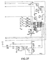
- the circuit shown in the schematic represents a combination of a gas furnace controller and an induced draft fan controller in which pressure switch 32 is replaced by pressure switch simulation means to be discussed below.
- the necessary logical interfaces defined in this approach are the induced draft fan enable signal and the simulated pressure switch enable signal.
- MOVM1 metal oxide varistor labeled MOVM1 is connected across the transformer secondary to limit excessive transient voltage surges that are coupled across the transformer (e.g., lightning spikes).
- Capacitor CM20 which is also connected across the transformer secondary provides differential mode filtering for high frequency signals which may be coupled through the transformer.
- the power is fed from the transformer secondary through fuse FM1 to a bridge rectifier.
- the fuse is a safety device which opens in the event excessive current is drawn as a result of a shorted component, shorted wiring or excessive load.
- Diodes DMB1, DMB2, DMB3 and DMB4 form a full wave bridge rectifier which converts the AC voltage supplied by the transformer into full wave rectified DC power.
- Capacitor CM21 integrates the rectified DC and removes the voltage ripple from the rectified DC power.
- Resistor RM4 which is in parallel with CM21 is a bleeder resistor which provides a minimum load and also discharges CM21 when the applied power is removed. The voltage generated by this supply is named VMRAIL and is used to drive the induced draft fan motor.
- AC power from the secondary of T1 passes through fuse FM1 it is also used as the input to a voltage doubler to generate a high voltage supply FET_HV used to turn on the gate of a N-channel power MOSFET QM1 which switches the power to the motor on and off.
- This voltage doubler is comprised of capacitors CC2 and CC5, resistors RR1 and RR3, and diodes DD2 and DD5.
- the AC wave form from the transformer secondary is coupled via fuse FM1 and capacitor CC5 into the common node of diodes DD2 and DD5.
- diode DD5 conducts charging CC5 to the half cycle peak voltage minus the diode drop from DD5.
- Diode DD5 is strongly reverse biased and does not conduct.
- Diode DD2 is forward biased and charges CC2 through resistor RR3 to twice the peak voltage minus two diode drops.
- Resistor RR1 is a high valued bleeder resistor which discharges CC2 when power is removed.
- the logic power supply is derived from a second power transformer whose secondary winding is connected to the terminals marked QC5 and QC6 shown in Fig. 2a.
- Capacitor C20 provides filtering of high frequency components that may be coupled through the transformer.
- Fuse F1 is a safety device which opens if excessive current is drawn from the transformer secondary. The power is then full wave rectified by a bridge rectifier comprised of diodes CR1, CR2, CR3 and CR4.
- Capacitor C12 provides additional high frequency filtering at the output of the bridge rectifier for high frequency components on the power line which may be coupled through the power transformer.
- RLAY_PWR This full wave rectified voltage is labeled RLAY_PWR and is used in this predominantly unfiltered state as a power source for the DC relays used in the system and to be discussed infra.
- RLAY_PWR is further rectified by diode CR5 whose output is integrated by capacitor C1 which removes the ripple from the rectified voltage. Diode CR5 also decouples the filtering action of capacitor C1 from RLAY_PWR.
- This filtered DC is named 24LOGIC on the schematic.
- Resistor R31 is a bleeder resistor which provides a minimum load and also discharges capacitor C1 when power is removed.
- the low voltage logic supply VDD is generated from 24LOGIC by the dropping resistor R1 and zener diode CR7.
- the zener voltage of diode CR7 sets the value of the VDD voltage.
- Resistor R1 sets the combined current for the load and the current shunted through diode CR7.
- Capacitor C2 provides additional filtering which removes most of the ripple from the supply VDD and provides a charge storage reservoir which can supply sudden current surge demands for the VDD supply without appreciably affecting the supply voltage.
- Capacitor C11 provides additional filtering of any high frequency signal components which might be present on the VDD supply.
- Resistor R16 discharges capacitors C2 and C11 when the power is removed.
- the EMF generated by the induced draft fan motor during the non-driven or “coasting" segment of the period labeled VMEMF is sampled by an analog input of the microprocessor UM2 (Fig. 2b).
- This signal is coupled from the motor terminal M+ labeled IDM_POS at terminal QCM2 through an attenuator/filter formed by resistors RM9, RM10 and CM4.
- Zener diode ZM4 limits the voltage at the microprocessor input to a voltage level which will not damage the microprocessor.
- the current drawn by the motor is sensed by monitoring the voltage across resistor RM13.
- Resistor RM13 which forms a voltage divider with the motor is a low value resistor through which the motor's current passes during the driven segment of the period. This voltage, which is proportional to the motor current, is low pass filtered by resistor RM11 and capacitor CM5.
- the filtered signal voltage is then amplified by an amplifier comprised of UM1 and resistors RM12, RM14 and RM15.
- the output of the amplifier labeled VMCUR is fed into an analog input of the microprocessor.
- Zener diode ZM9 subtracts a fixed DC voltage from VMRAIL.
- Resistors RM18 and RM19 and capacitor CM9 form an attenuator/filter for the voltage VMRAIL - V ZM9 providing a voltage labeled VMSENSE which is fed into an analog input of the microprocessor.
- Zener diode ZM6 provides a clamp for the microprocessor input which prohibits the input voltage from reaching destructive levels.
- the microprocessor performs analog-to-digital conversions of these three analog signals and calculates a pulse width used to drive transistors QM1 and QM2 which, in turn, drive the motor connected between terminals M+ (QCM2) and M- (QCM3).
- the microprocessor implements the algorithm described infra.
- the microprocessor output signal MPWMDRV is a variable pulse width logic level signal whose complement determines the drive duty cycle for the motor. When the MPWMDRV signal is at a logic low, transistor QM2 is in the OFF state. The collector of QM2 is pulled up through load resistor RM1 to the voltage FET_HV. The voltage at the collector of transistor QM2 is connected to the gate of transistor QM1.
- MOSFET QM1 When the gate voltage rises to a value which exceeds the EMF voltage of the motor by a diode drop plus a MOSFET threshold voltage, MOSFET QM1 begins to conduct current from the VMRAIL supply. As the gate voltage increases above VMRAIL, the motor drive voltage becomes clamped at VMRAIL.
- resistor RM6 and RM8 When MPWMDRV goes to a logic high level resistors RM6 and RM8 initially form an attenuator (voltage divider). After transistor QM2 begins to conduct, resistor RM8 determines the base current for QM2. Resistor RM6 acts to enhance the turn-off speed of transistor QM2 by providing a discharge path for the charge stored in the base-emitter region of transistor QM2. As transistor QM2 begins to conduct, the collector voltage is pulled from FET_HV to a saturation voltage above ground. As the gate voltage of transistor QM1 is pulled to ground, it is turned off and conduction of the motor current from the supply VMRAIL ceases.
- Oscillator OSCM1 is a ceramic resonator or quartz crystal which determines the clock frequency for the microprocessor.
- Resistor RM7 provides a weak leakage path around the resonator or crystal to aid in starting the oscillator.
- Resistors RM80, RM81, RM82 and RM83 and their associated switches are used to change the firmware configuration of the microprocessor as required, for example, for selecting different fan air flow rates.
- the induced draft fan is enabled by the IND_DRV output from the furnace control microprocessor U2.
- the enabling signal is a pulse train which normally drives a relay through a circuitry arrangement similar to that shown for relay K4.
- the use of the pulse train is a safety precaution which will turn the fan off in the event of either a stuck at "1" or a stuck at "0" condition failure.
- the relay is replaced by circuitry which rectifies the pulse train and conditions the signal for use by the motor control microprocessor UM2.
- Resistor RM23(Fig. 2b) is a pull-up resistor for the relay drive U1 which serves as an inverting buffer.
- the buffered signal (IDM_DRV) is then AC coupled through capacitor CM11.
- Resistor RM24 provides a load for the AC coupled signal and provides a DC return path for the subsequent rectification process through diode DM6, resistor RM25, and zener diode ZM10.
- Diode DM6 rectifies the AC coupled signal.
- Resistor RM25 limits the current flowing through zener diode ZM10 which limits the voltage to a safe level for the microprocessor input.
- Capacitor CM12 provides filtering for the rectified wave form. The resulting signal is applied to an input of motor control microprocessor UM2.
- Microprocessor UM2 compares the fan motor's EMF and current against limits stored in its memory to determine if air flow is adequate to provide safe combustion characteristics for the gas furnace. If adequate air flow exists, microprocessor UM2 outputs a pulsed drive signal to transistor QM3 through base current limiting resistor RM21.
- the use of a pulsed drive signal is a safety measure which will cause the relay to release if either a stuck at "1" or a stuck at "0" condition develops for the enabling signal.
- Transistor QM3, resistor RM20, and diode DM5 invert and buffer the drive signal.
- capacitor CM8 When the collector of transistor QM3 is pulled up by the supply RLAY_PWR, capacitor CM8 is charged through diodes DM3 and DM5 and resistor RM20. When transistor QM3 is turned on, its collector is pulled to a saturation voltage above ground. Pulling the positive terminal of capacitor CM8 to near ground causes its negative terminal to go to a negative potential whose magnitude is slightly less than the magnitude of the RLAY_PWR supply. Diode DM3 is reverse biased and conduction through DM3 ceases. The capacitor CM8 begins to discharge through the coil of relay KM1 which energizes the relay. When the charge-discharge cycle is repeated rapidly, the relay will remain energized. The contacts of relay KM1, under the control of the microprocessor, replace the contacts of a conventional pressure switch, as will be discussed further below.
- the enabling signal for the furnace control is the Call for Heat (W) signal from the room thormostat.
- W Call for Heat
- the transformer secondary line R is connected through the closed thermostat switch to the terminal labeled W.
- the pressure simulation switch which is normally connected between the PSIN and PSOUT is closed, the 24 volts AC will now be present on one of the contacts of the gas valve relay K4.
- Relay K5 turns on the gas ignitor prior to energizing the gas valve relay to permit the ignitor to reach ignition temperature prior to releasing gas. Following this delay the gas valve relay is energized which opens the gas valve and combustion is initiated.
- thermostat switch closure is detected by the microprocessor through an attenuator circuit formed by resistors R7 and R35. Resistor R5 limits current through the clamp diodes at the microprocessor input.
- the thermostat switch When the thermostat switch is open, the voltage at the junction of R7 and R35 with respect to logic ground is a half sinusoid which has a peak amplitude of approximately 40 volts.
- the thermostat switch closes the voltage wave form at this node is made up of two half wave rectified peaks which appear as unequal amplitude full wave rectified half cycle peaks.
- the peak from the thermostat input has an amplitude of Vpeak [R35 / (R7 + R35)] while the peak from the chassis ground input has an amplitude of Vpeak [R7 / (R7 + R35)].
- the microprocessor In order to detect the presence or absence of the half cycle peak from the W line, the microprocessor must make a determination of the appropriate time to obtain a signal sample. This is determined by a sample from the R side of the transformer secondary. This signal is attenuated by the divider formed by resistors R2 and R20. Resistor R2 also limits the current through the input clamp diodes in the microprocessor. Capacitor C4 provides filtering of high frequency signal components associated with this signal.
- This signal which is a positive half cycle of the AC supply, is clipped at the VDD level for the microprocessor. This signal is fed to the Interrupt Request line and to an input of the microprocessor. On the falling edge of this waveform, the IRQ signal for the microprocessor is activated which initiates a counter in the microprocessor that counts until this wave form on the microprocessor inputs reaches a half cycle or a full cycle transition boundary. This count effectively determines the period of the AC supply. Based upon this value, the sampling point for the peak of the half cycle due to the presence of an AC wave form at W is determined. Similar circuits are used at the nodes following the pressure simulation switch function and the signal fed back from across the gas valve solenoid. The fan control input (G) from the thermostat is also sensed by the microprocessor by an identical method.
- LIMIT_IN provides a fused source of 24 volts AC which is passed through a string of normally closed limit switches referenced above to the LIMIT_OUT terminal.
- the LIMIT_OUT terminal then supplies power to the thermostat. If any of the thermal limit switches open, power is removed from the thermostat which will inhibit furnace operation.
- the microprocessor also detects the open thermal limit switch directly via resistor R6 which limits current through the input clamping diodes of the microprocessor. Resistor R18 is a load resistor.
- the gas valve closure signal is also passed to the motor control microprocessor UM2 via cascaded inverters in U3 in order to avoid unsafe operation in the event of a failure of furnace control microprocessor U2.
- the gas valve is off, half cycle pulses from chassis ground couple through the deenergized solenoid coil into the gas valve sample terminal GV.
- the solenoid When the solenoid is energized, the half cycle supplied by the R lead via the limit switches, thermostat, pressure switch (or the equivalent), and gas valve relay becomes the signal at the GV terminal.
- the impedance of the solenoid effectively blocks the half cycle from the chassis ground.
- the wave form at the GV input appears to change half cycle positions when the gas valve is energized.
- the inverters in U3 limit the amplitude of the output signal MV3 to a logic level swing.
- the 24 volt AC signal relative to logic ground is a half cycle peak corresponding to the positive half cycle at R.
- Resistor RM90 and diode DM90 effectively perform a logic AND function between MV3 and the positive half cycle of R which corresponds to the signal condition for a closed gas valve.
- Resistors RM90 and RM91 attenuate the MV3 signal while RM90 will limit the clamp diode current in the input of the microprocessor UM2 if the signal MV3 exceeds the input range.
- Capacitor CM90 and diode DM91 provides filtering.
- Resistors RM92 and RM93 form an attenuator for the 24 volt AC signal which is applied to the interrupt request line (MIRQ) for the motor control microprocessor UM2.
- MIRQ interrupt request line
- RM92 provides current limiting for the clamping diodes in the input circuitry of microprocessor UM2.
- Capacitor CM91 provides filtering.
- the reset line for the microprocessor U2 is driven from the 24LOGIC supply through a voltage dropping zener diode CR28 and an attenuator formed by resistors R28 and R30.
- a clamping zener diode CR6 limits the input voltage to the microprocessor.
- Capacitor C9 delays the rise of the reset wave form from that of the 24LOGIC supply and the VDD supply for the microprocessor.
- Oscillator OSC1 is a ceramic resonator which determines the oscillator frequency for the microprocessor. The internal timing for the microprocessor is determined by this frequency.
- Resistor R10 is a leak resistor which aids in starting the oscillator.
- the twinning circuitry utilizes a microprocessor output and an input in conjunction with resistors R41, R42, R43, and R51, zener diode CR12, and a relay driver in U1.
- the twin connection is a bidirectional interlock port for synchronizing the operation of two furnaces when desired.
- Microprocessor outputs buffered by relay drivers in U1 control various relays which in turn control various components of the gas furnace.
- Relay K1 enables the air handler blower.
- Relay K2 selects the blower speed.
- Relay K5 enables the ignitor, and relay K4 enables the gas valve after a suitable time delay.
- a buffered microprocessor output also flashes LED1 which is used for diagnostic reporting.
- Resistor R29 limits the LED current.
- the 90+_IN terminal is a configuration port which configures the internal microprocessor firmware for two types of furnaces having slightly different characteristics.
- the flame sense circuit is comprised of capacitors C5 and C6, resistors Rll, R22, and R26, and an inverter from U3.
- the flame acts as a high value resistor in series with a diode whose cathode is connected to chassis ground.
- the line voltage AC wave form is clipped to a value dependent upon the reactance of capacitor C6, the value of resistor R25, and the equivalent resistance of the flame.
- the rectification causes the average value of the voltage at the R22, R26, and C6 node to become negative.
- resistor R11 Prior to the initiation of flame, resistor R11 charges capacitor C5 to VDD. With flame present the negatively biased node described above discharges capacitor C5.
- each point on the curve which includes points A and B corresponds to an operating point for a particular fan at a selected flow rate of 21 CFM (cubic feet per minute). If, at a given point for the referenced fan, the actual V EMF is above the curve, then the duty cycle must be raised to increase the load on the fan and bring the actual operating point closer to the new point on the curve. The reverse applies if the actual V EMF is below the curve for a specific current.
- the control process is iterative. Motor current I M is used to compute a desired voltage, the actual V EMF is subtracted from the desired voltage to get a relative error, and the duty cycle is adjusted according to the direction and magnitude of the error. After giving the motor some time to settle into the new duty cycle, the process is repeated continually attempting to bring the operating point onto the curve.
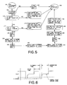
- Figs. 4 and 5 show a basic flow chart for the microprocessor code in a preferred embodiment.
- Fig. 4 describes the main routine, which is executed continuously.
- Fig. 5 describes the interrupt handler which produces the actual PWM waveform and measures the motor parameters for use by the main routine. The interrupt handler takes control from the main routine on a periodic basis when it is time to switch the state of the motor drive.
- the controller when the controller is energized at 100, it sets a nominal starting duty cycle (e.g. 20%) as shown at 102.
- the next steps 104 and 106 ensure that the low pressure relay KM1 and the induced draft fan motor are both turned off.
- the routine goes back to step 104 and stays in that loop.
- the motor drive is enabled.
- values for motor current (I m ), motor EMF voltage (V emf ), and applied motor voltage (Vapp) are read from memory. These values are constantly updated by the interrupt handling routine shown in Fig. 5 to be discussed infra.
- the desired EMF voltage (Vdesired) is computed at 114 from motor current Im utilizing a programmed curve of I m vs Vemf for a selected air flow rate and a selected fan/motor combination which is stored in the microprocessors memory prior to shipment.
- the error voltage (Verr) is computed in 116 by subtracting the Vdesired from Vemf.
- the new duty cycle is computed by adding the error voltage Verr multiplied by a gain to the current duty cycle with the gain proportional to the magnitude of error voltage Verr so that a smooth, fast response time is obtained for the system.
- a decision is made at 120 as to whether the motor EMF voltage Vemf is within tolerable limits for proper motor operation and if not, the duty cycle is adjusted at 122 to attempt to bring the motor within tolerable limits. Regardless of the decision made at 120, a new decision is made at 124 to determine if the motor EMF voltage Vemf is within range for pressure switch relay (PS) closure and if not then the flow skips to 129.
- PS pressure switch relay
- a nominal percentage e.g. 50%
- the interrupt handler routine is entered at 160 whenever the timer signals that it is time for another interrupt.
- the motor is turned off at 164 and the interrupt is exited at 166 otherwise a decision is made at 168 as to whether the motor is currently in the off-phase of PWM operation. If the decision at 168 is false, then the motor is turned off at 170 and the interrupt timer is set to signal the next interrupt at the appropriate time based on the current duty cycle and PWM period prior to exit at 166.
- Vmf 16 samples of motor EMF voltage Vemf are read, summed, and stored prior to turning the motor back on at 186 and setting the interrupt timer to signal the next interrupt at the appropriate time at 188.
- the sums for Vemf and Vapp are divided by 16 to produce an average value for the two variables and the sum for Im is divided by 32 for averaging purposes prior to saving values for Vemf, Im, and Vapp for use by the main routine at 192 and exiting the handler at 166.
- a suitable duty cycle (e.g. 50%) is employed for reading the samples. Since the sampling process alters the operation of the motor, each sample period is separated by at least N PWM cycles where N is chosen to be between 10 and 1000 depending on PWM frequency. By way of example in a system made in accordance with the invention with a PWM frequency of 200 Hz, N is 32.
- the flow chart of Fig. 4 described above provides low pressure protection without the use of a conventional low pressure sensor 32 shown in Fig. 1.
- Such pressure sensors are relatively expensive as well as adding to potential field problems.
- the function of pressure switch 32 is to ensure that the venting system is operational and hazardous combustion gases such as carbon monoxide will not be forced into the heated air space.
- the pressure switch is responsive to a number of conditions including blocked or highly restricted vents, induced draft fan failure, inadequate induced draft fan performance and loose fan impellers.
- V EMF of a DC motor provides feedback which is linearly proportional to the speed (RPM) of the motor.
- Current I m drawn by the motor is similarly linearly proportional to torque generated by the motor.
- the blocked or partially blocked vent can be detected and inhibited by prohibiting operation above a selected value of V EMF and I m point on the curve which correspond to the maximum allowable back pressure.
- the point labeled A in the figure represents such a point.
- Operation with a failed induced draft fan or with inadequate flow or back pressure can be inhibited by requiring operation above a V EMF and I m point on the operating curve which corresponds to the minimum acceptable back pressure at the desired flow rate for the fan.
- the point labeled B in the figure represents such a point.
- the loose impeller can be detected by requiring a minimum motor current to enable furnace operation. Under this condition the motor is operating without a load.
- the curve indicated by the circles in Fig. 3 represents reduced current drawn by the motor under unloaded conditions.
- a control system made in accordance with the Fig. 2 embodiment comprised the following components.
- the data sampling process "piggy backs" onto the pulse width modulated wave form.
- the PWM wave form received by the motor is not changed by the sampling process.
- the control first waits for the motor to turn on and then continually takes samples of motor current until the motor turns off again. As soon as the motor turns off, the control starts sampling the EMF voltage and continues to do so until the motor turns on again.
- the actual number of samples for each parameter depends on the duty cycle of the motor.
- the applied voltage is also read the same way as the motor current but during a different cycle. The reading of all three parameters constitutes a complete sample period. After a complete sample period, all of the motor current data is summed and averaged over the entire PWM period.
- the EMF voltage is compared to a threshold to eliminate erroneous data during the flyback time. All values which exceed the threshold are averaged together. The applied voltage values are simply averaged. All three data values are then averaged with the data from previous sample periods to smooth the input signals.
Landscapes
- Engineering & Computer Science (AREA)
- Chemical & Material Sciences (AREA)
- Combustion & Propulsion (AREA)
- Mechanical Engineering (AREA)
- General Engineering & Computer Science (AREA)
- Control Of Positive-Displacement Air Blowers (AREA)
- Regulation And Control Of Combustion (AREA)
Applications Claiming Priority (2)
| Application Number | Priority Date | Filing Date | Title |
|---|---|---|---|
| US489274 | 1995-06-09 | ||
| US08/489,274 US5524556A (en) | 1995-06-09 | 1995-06-09 | Induced draft fan control for use with gas furnaces |
Publications (2)
| Publication Number | Publication Date |
|---|---|
| EP0747632A2 true EP0747632A2 (de) | 1996-12-11 |
| EP0747632A3 EP0747632A3 (de) | 1997-09-10 |
Family
ID=23943149
Family Applications (1)
| Application Number | Title | Priority Date | Filing Date |
|---|---|---|---|
| EP96304133A Withdrawn EP0747632A3 (de) | 1995-06-09 | 1996-06-05 | Gebläseregelung eines erzwungenen Abzug für einen Gasofen |
Country Status (2)
| Country | Link |
|---|---|
| US (3) | US5524556A (de) |
| EP (1) | EP0747632A3 (de) |
Families Citing this family (78)
| Publication number | Priority date | Publication date | Assignee | Title |
|---|---|---|---|---|
| KR100295087B1 (ko) * | 1995-09-27 | 2001-09-17 | 전주범 | 가스보일러의역풍감지방법 |
| JP3795951B2 (ja) * | 1996-01-31 | 2006-07-12 | 三洋電機株式会社 | 低NOxバーナおよび排ガス再循環制御方法 |
| US5771879A (en) * | 1996-03-22 | 1998-06-30 | Captive-Aire Systems, Inc. | Heated makeup air system for a commercial kitchen |
| US6570361B1 (en) * | 1999-02-22 | 2003-05-27 | Borealis Technical Limited | Rotating induction apparatus |
| US6037732A (en) * | 1996-11-14 | 2000-03-14 | Telcom Semiconductor, Inc. | Intelligent power management for a variable speed fan |
| US6040668A (en) * | 1996-11-14 | 2000-03-21 | Telcom Semiconductor, Inc. | Monolithic fan controller |
| US5924390A (en) * | 1997-02-28 | 1999-07-20 | Bock; John C. | Water heater with co-located flue inlet and outlet |
| US6000622A (en) * | 1997-05-19 | 1999-12-14 | Integrated Control Devices, Inc. | Automatic control of air delivery in forced air furnaces |
| US5947691A (en) * | 1997-10-29 | 1999-09-07 | Comair Rotron, Inc. | Winding supply circuit with current and thermal protective elements |
| US6053130A (en) * | 1998-06-04 | 2000-04-25 | American Water Heater Company | Power vent water heater with electronic control system |
| WO2000002159A1 (en) * | 1998-07-07 | 2000-01-13 | Koninklijke Philips Electronics N.V. | Data carrier provided with data processing means and current peak pattern suppression means |
| US6257870B1 (en) | 1998-12-21 | 2001-07-10 | American Standard International Inc. | Gas furnace with variable speed draft inducer |
| US6257832B1 (en) * | 1999-02-04 | 2001-07-10 | Dell Usa, L.P. | Multiple fan system having means for reducing beat frequency oscillations |
| US6082993A (en) * | 1999-05-28 | 2000-07-04 | H-Tech, Inc. | Induced draft heater with premixing burners |
| US6481019B2 (en) * | 2000-01-18 | 2002-11-19 | Stryker Instruments | Air filtration system including a helmet assembly |
| DE10002349C2 (de) * | 2000-01-20 | 2001-11-29 | Armin Spaniol | Feuerwehrübungsanlage |
| US7651034B2 (en) * | 2000-08-04 | 2010-01-26 | Tjernlund Products, Inc. | Appliance room controller |
| US6726111B2 (en) | 2000-08-04 | 2004-04-27 | Tjernlund Products, Inc. | Method and apparatus for centrally controlling environmental characteristics of multiple air systems |
| US6758208B2 (en) * | 2001-01-17 | 2004-07-06 | Technologies Echangeur Gaz Air (Tega) Inc. | Flexible gas-fired heat exchanger system |
| DE10109808C2 (de) * | 2001-03-01 | 2003-12-04 | Bosch Gmbh Robert | Verfahren und Vorrichtung zur Anpassung eines brennerbetriebenen Heizgerätes an ein Luft-Abgas-System |
| US6504338B1 (en) * | 2001-07-12 | 2003-01-07 | Varidigm Corporation | Constant CFM control algorithm for an air moving system utilizing a centrifugal blower driven by an induction motor |
| US6557501B2 (en) | 2001-08-02 | 2003-05-06 | Aos Holding Company | Water heater having flue damper with airflow apparatus |
| US20050280384A1 (en) * | 2001-09-05 | 2005-12-22 | Sulfstede Louis E | Air delivery system and method |
| US20030042860A1 (en) * | 2001-09-05 | 2003-03-06 | Sulfstede Louis E. | System and method of controlling airflow in an air delivery system |
| US7101172B2 (en) * | 2002-08-30 | 2006-09-05 | Emerson Electric Co. | Apparatus and methods for variable furnace control |
| CA2497992A1 (en) * | 2002-09-09 | 2004-03-18 | Comair Rotron, Inc. | Draft inducer system |
| DE10254202B4 (de) * | 2002-11-20 | 2006-05-18 | Siemens Ag | Vorrichtung und Verfahren zum Erkennen der Sitzbelegung in einem Fahrzeug |
| US20040145324A1 (en) * | 2003-01-28 | 2004-07-29 | Ross Christian E. | Integrated control device for environmental systems |
| US20050048427A1 (en) * | 2003-09-03 | 2005-03-03 | Brown Fred A. | Draft inducer performance control |
| CA2541945A1 (en) * | 2003-09-03 | 2005-03-17 | Comair Rotron, Inc. | Apparatus and method for maintaining an operating condition for a blower |
| US8593768B2 (en) * | 2003-12-08 | 2013-11-26 | Rockwell Automation Technologies, Inc. | Apparatus and method for disabling the operation of high power devices |
| US7123020B2 (en) * | 2004-06-28 | 2006-10-17 | Honeywell International Inc. | System and method of fault detection in a warm air furnace |
| US7048537B2 (en) * | 2004-10-12 | 2006-05-23 | Emerson Electric Co. | Apparatus and method for controlling a variable fuel fired appliance |
| US20060228294A1 (en) * | 2005-04-12 | 2006-10-12 | Davis William H | Process and apparatus using a molten metal bath |
| US7573217B2 (en) * | 2005-05-31 | 2009-08-11 | Regal-Beloit Corporation | Methods and systems for automatic rotation direction determination of electronically commutated motor |
| US20060275719A1 (en) * | 2005-06-07 | 2006-12-07 | Honeywell International Inc. | Warm air furnace baselining and diagnostic enhancements using rewritable non-volatile memory |
| EP1772960B1 (de) * | 2005-10-07 | 2009-03-04 | Emotron AB | Lastüberwachung |
| US7748375B2 (en) * | 2005-11-09 | 2010-07-06 | Honeywell International Inc. | Negative pressure conditioning device with low pressure cut-off |
| US7644712B2 (en) * | 2005-11-09 | 2010-01-12 | Honeywell International Inc. | Negative pressure conditioning device and forced air furnace employing same |
| US8635997B2 (en) * | 2006-10-18 | 2014-01-28 | Honeywell International Inc. | Systems and methods for controlling gas pressure to gas-fired appliances |
| US8591221B2 (en) * | 2006-10-18 | 2013-11-26 | Honeywell International Inc. | Combustion blower control for modulating furnace |
| US20080124667A1 (en) | 2006-10-18 | 2008-05-29 | Honeywell International Inc. | Gas pressure control for warm air furnaces |
| US8075304B2 (en) * | 2006-10-19 | 2011-12-13 | Wayne/Scott Fetzer Company | Modulated power burner system and method |
| MY167120A (en) * | 2006-11-10 | 2018-08-10 | Oyl Res & Development Centre Sdn Bhd | An apparatus for controlling an air distribution system |
| US8672733B2 (en) | 2007-02-06 | 2014-03-18 | Nordyne Llc | Ventilation airflow rate control |
| US7770806B2 (en) | 2007-06-19 | 2010-08-10 | Nordyne Inc. | Temperature control in variable-capacity HVAC system |
| JP2009109124A (ja) * | 2007-10-31 | 2009-05-21 | Daikin Ind Ltd | 調湿装置 |
| PL383941A1 (pl) * | 2007-12-03 | 2009-06-08 | Witold Kowalewski | Kocioł rusztowy, sposób modernizacji kotła rusztowego oraz sposób likwidowania szkodliwych przedmuchów powietrza, nie biorącego udziału w procesie spalania w kotle rusztowym |
| US8070481B2 (en) * | 2008-05-27 | 2011-12-06 | Honeywell International Inc. | Combustion blower control for modulating furnace |
| US9316413B2 (en) * | 2008-06-11 | 2016-04-19 | Honeywell International Inc. | Selectable efficiency versus comfort for modulating furnace |
| US8123518B2 (en) | 2008-07-10 | 2012-02-28 | Honeywell International Inc. | Burner firing rate determination for modulating furnace |
| US20100256821A1 (en) * | 2009-04-01 | 2010-10-07 | Sntech Inc. | Constant airflow control of a ventilation system |
| US8777119B2 (en) * | 2009-10-02 | 2014-07-15 | Captive-Aire Systems, Inc. | Heated makeup air unit |
| DE102009048405A1 (de) * | 2009-10-06 | 2011-04-07 | Honeywell Technologies S.A.R.L. | Regeleinrichtung für Gasbrenner |
| US8261733B2 (en) * | 2009-11-03 | 2012-09-11 | Trane International Inc. | Modulating gas furnace |
| DE102010010791A1 (de) * | 2010-03-09 | 2011-09-15 | Honeywell Technologies Sarl | Mischvorrichtung für einen Gasbrenner |
| IT1399076B1 (it) * | 2010-03-23 | 2013-04-05 | Idea S R L Ora Idea S P A | Dispositivo e metodo di controllo della portata di aria comburente di un bruciatore in genere |
| CA2753549A1 (en) * | 2010-10-05 | 2012-04-05 | Carrier Corporation | Method and system for controlling an inducer in a modulating furnace |
| US8560127B2 (en) | 2011-01-13 | 2013-10-15 | Honeywell International Inc. | HVAC control with comfort/economy management |
| US9200847B2 (en) | 2011-02-07 | 2015-12-01 | Carrier Corporation | Method and system for variable speed blower control |
| CN102072489B (zh) * | 2011-02-25 | 2012-07-04 | 凯明企业有限公司 | 燃烧器 |
| US10094591B2 (en) | 2011-08-15 | 2018-10-09 | Carrier Corporation | Furnace control system and method |
| AU2013200950B2 (en) * | 2012-02-16 | 2014-05-29 | David M. Christensen | Control system for space heater/hearth |
| US8876524B2 (en) | 2012-03-02 | 2014-11-04 | Honeywell International Inc. | Furnace with modulating firing rate adaptation |
| ITVI20120294A1 (it) * | 2012-10-30 | 2014-05-01 | Extraflame S P A | Procedimento di controllo del funzionamento dei motori di aspirazione fumi in apparecchi riscaldanti a combustibile solido |
| US9212821B2 (en) * | 2013-02-20 | 2015-12-15 | Emerson Electric Co. | Systems and methods for controlling multistage electronic controlled gas valves |
| US10145569B2 (en) * | 2014-04-15 | 2018-12-04 | David S. Thompson | Air handling vent control |
| KR101655009B1 (ko) * | 2015-01-16 | 2016-09-06 | 엘지전자 주식회사 | 조리기기 및 그의 제어방법 |
| US10802459B2 (en) | 2015-04-27 | 2020-10-13 | Ademco Inc. | Geo-fencing with advanced intelligent recovery |
| DE102016117323B3 (de) * | 2016-09-14 | 2017-11-02 | Valeo Thermal Commercial Vehicles Germany GmbH | Verfahren zur Konstanthaltung des dem Brennerraum eines mobilen Heizgerätes zugeführten Verbrennungsluft-Massenstroms und nach einem solchen Verfahren arbeitendes Heizgerät |
| DE102017126138A1 (de) * | 2017-11-08 | 2019-05-09 | Ebm-Papst Landshut Gmbh | Verfahren zur Regelung eines brenngasbetriebenen Heizgerätes |
| US10753623B2 (en) * | 2018-02-15 | 2020-08-25 | Johnson Controls Technology Company | Flame control systems and methods for furnaces |
| US10935238B2 (en) | 2018-05-23 | 2021-03-02 | Carrier Corporation | Furnace with premix ultra-low NOx (ULN) burner |
| US10451303B1 (en) * | 2018-07-30 | 2019-10-22 | Rheem Manufacturing Company | Electronic detection of vent blockage and blower malfunction in temperature control systems |
| PT111114B (pt) * | 2018-08-30 | 2024-12-19 | Bosch Termotecnologia Sa | Processo para regular um dispositivo de aquecimento |
| US11486576B2 (en) * | 2019-08-23 | 2022-11-01 | Regal Beloit America, Inc. | System and method for burner ignition using sensorless constant mass flow draft inducers |
| CN110705609B (zh) * | 2019-09-16 | 2022-04-12 | 中国神华能源股份有限公司国华电力分公司 | 引风机运行状态诊断方法、装置及电子设备、存储介质 |
| US11340569B2 (en) * | 2019-11-07 | 2022-05-24 | Ademco Inc. | Electronic air pressure interlock switch |
Family Cites Families (27)
| Publication number | Priority date | Publication date | Assignee | Title |
|---|---|---|---|---|
| US3924605A (en) * | 1971-12-02 | 1975-12-09 | James A Weinman | Emission control method and apparatus for smokestacks or other waste gas discharge stacks |
| US3964675A (en) * | 1974-10-15 | 1976-06-22 | Euchner Jr Perry C | Appartus for limiting vacuum and pressure in a furnace |
| US4185685A (en) * | 1978-01-03 | 1980-01-29 | Giberson Elwood C | Waste heat recovery system and method |
| US4204832A (en) * | 1978-08-10 | 1980-05-27 | Modine Manufacturing Company | Gas burner device |
| US4205631A (en) * | 1978-10-11 | 1980-06-03 | Westinghouse Electric Corp. | Pressure limiting control for an inlet draft fan in an electric power plant |
| US4485746A (en) * | 1981-12-07 | 1984-12-04 | Kelley Company, Inc. | Energy recovery system for an incinerator |
| US4402303A (en) * | 1982-01-28 | 1983-09-06 | Koenneman Donald E | Fan flow control device |
| US4487137A (en) * | 1983-01-21 | 1984-12-11 | Horvat George T | Auxiliary exhaust system |
| US4638233A (en) * | 1985-10-24 | 1987-01-20 | General Electric Company | Method of establishing a preferred rate of air flow, method of determining torque, and apparatus |
| US4860231A (en) * | 1985-12-16 | 1989-08-22 | Carrier Corporation | Calibration technique for variable speed motors |
| US4648551A (en) * | 1986-06-23 | 1987-03-10 | Carrier Corporation | Adaptive blower motor controller |
| US4688547A (en) * | 1986-07-25 | 1987-08-25 | Carrier Corporation | Method for providing variable output gas-fired furnace with a constant temperature rise and efficiency |
| US4703747A (en) * | 1986-09-17 | 1987-11-03 | Carrier Corporation | Excess air control |
| US4829703A (en) * | 1987-08-04 | 1989-05-16 | Gas Research Institute | Auxiliary flue for furnaces |
| US4789330A (en) * | 1988-02-16 | 1988-12-06 | Carrier Corporation | Gas furnace control system |
| US4907737A (en) * | 1989-03-30 | 1990-03-13 | R. E. Phelon Company, Inc. | Electronic control system for a gas-fired/hot air furnace with induced draft blower |
| US4978896A (en) * | 1989-07-26 | 1990-12-18 | General Electric Company | Method and apparatus for controlling a blower motor in an air handling system |
| DE3928114C2 (de) * | 1989-08-25 | 1994-02-10 | Webasto Ag Fahrzeugtechnik | Verfahren zur Steuerung eines über einen Motor angetriebenen Brennluftgebläses für ein Heizgerät |
| US5019757A (en) * | 1990-03-19 | 1991-05-28 | General Electric Company | Method and apparatus for controlling a blower motor in an air handling system to provide constant pressure |
| US5272427A (en) * | 1992-05-20 | 1993-12-21 | Texas Instruments Incorporated | Furnace control apparatus and method |
| JPH06117625A (ja) * | 1992-10-01 | 1994-04-28 | Hitachi Chem Co Ltd | 燃焼機器用送風機の制御方法及び燃焼機器用送風機 |
| US5279234A (en) * | 1992-10-05 | 1994-01-18 | Chiptec Wood Energy Systems | Controlled clean-emission biomass gasification heating system/method |
| US5616995A (en) * | 1993-02-22 | 1997-04-01 | General Electric Company | Systems and methods for controlling a draft inducer for a furnace |
| DE9310451U1 (de) * | 1993-03-05 | 1994-06-30 | Landis & Gyr Business Support Ag, Zug | Steuer- bzw. Regeleinrichtung für Gas-Feuerungsautomaten von Heizungsanlagen |
| US5331944A (en) * | 1993-07-08 | 1994-07-26 | Carrier Corporation | Variable speed inducer motor control method |
| JP3185504B2 (ja) * | 1993-11-08 | 2001-07-11 | 株式会社ノーリツ | 燃焼制御装置 |
| US5447414A (en) * | 1994-05-27 | 1995-09-05 | Emerson Electric Co. | Constant air flow control apparatus and method |
-
1995
- 1995-06-09 US US08/489,274 patent/US5524556A/en not_active Expired - Fee Related
- 1995-11-16 US US08/559,216 patent/US5720231A/en not_active Expired - Fee Related
-
1996
- 1996-05-20 US US08/651,009 patent/US5806440A/en not_active Expired - Fee Related
- 1996-06-05 EP EP96304133A patent/EP0747632A3/de not_active Withdrawn
Also Published As
| Publication number | Publication date |
|---|---|
| US5806440A (en) | 1998-09-15 |
| US5720231A (en) | 1998-02-24 |
| US5524556A (en) | 1996-06-11 |
| EP0747632A3 (de) | 1997-09-10 |
Similar Documents
| Publication | Publication Date | Title |
|---|---|---|
| EP0747632A2 (de) | Gebläseregelung eines erzwungenen Abzug für einen Gasofen | |
| US5222888A (en) | Advanced proof-of-rotation switch | |
| JP2617256B2 (ja) | 空気調和機の電流制御装置及び制御方法 | |
| US20040167673A1 (en) | Temperature control apparatus for a heater using an encoder switch and method thereof | |
| JPH0695808B2 (ja) | 誘導電動機の制御回路及び制御方法 | |
| WO2008024918A2 (en) | Producing a constant air flow from a blower | |
| US3912162A (en) | Furnace blower speed control | |
| JPH06317319A (ja) | 暖房装置のガス自動燃焼制御装置用の制御装置とその使用方法 | |
| JPH0789005B2 (ja) | 電子レンジを備えた冷蔵庫の制御回路 | |
| JP3096553B2 (ja) | 送風ファンの駆動装置 | |
| US5261811A (en) | Burner control system and method | |
| US4189091A (en) | Furnace having a normally closed blower relay | |
| JP3339245B2 (ja) | モータ制御装置 | |
| JP2838973B2 (ja) | 燃焼用ファン制御装置 | |
| JP3360540B2 (ja) | 温風暖房機の制御装置 | |
| JP3021763B2 (ja) | 温風暖房機 | |
| JPH01116451A (ja) | 回転数検出回路 | |
| KR960007653B1 (ko) | 배기팬 제어회로 | |
| JPH0625798Y2 (ja) | 室温制御装置 | |
| JP3558435B2 (ja) | 燃焼機器 | |
| JPH0311387B2 (de) | ||
| KR890006468Y1 (ko) | 기화기 온도 과도 상승 방지회로 | |
| KR19980059061U (ko) | 가스보일러의 배기팬 구동회로 | |
| JPS59106881A (ja) | 空調用インバ−タの保護方式 | |
| JP3598481B2 (ja) | 電気掃除機の入力制御装置 |
Legal Events
| Date | Code | Title | Description |
|---|---|---|---|
| PUAI | Public reference made under article 153(3) epc to a published international application that has entered the european phase |
Free format text: ORIGINAL CODE: 0009012 |
|
| AK | Designated contracting states |
Kind code of ref document: A2 Designated state(s): DE FR GB IT NL |
|
| PUAL | Search report despatched |
Free format text: ORIGINAL CODE: 0009013 |
|
| AK | Designated contracting states |
Kind code of ref document: A3 Designated state(s): DE FR GB IT NL |
|
| STAA | Information on the status of an ep patent application or granted ep patent |
Free format text: STATUS: THE APPLICATION IS DEEMED TO BE WITHDRAWN |
|
| 18D | Application deemed to be withdrawn |
Effective date: 19980311 |