EP0747655A2 - Vielseitiger Autopilot für Raketen - Google Patents
Vielseitiger Autopilot für Raketen Download PDFInfo
- Publication number
- EP0747655A2 EP0747655A2 EP96303437A EP96303437A EP0747655A2 EP 0747655 A2 EP0747655 A2 EP 0747655A2 EP 96303437 A EP96303437 A EP 96303437A EP 96303437 A EP96303437 A EP 96303437A EP 0747655 A2 EP0747655 A2 EP 0747655A2
- Authority
- EP
- European Patent Office
- Prior art keywords
- autopilot
- missile
- tail
- tails
- ref
- Prior art date
- Legal status (The legal status is an assumption and is not a legal conclusion. Google has not performed a legal analysis and makes no representation as to the accuracy of the status listed.)
- Withdrawn
Links
Images




Classifications
-
- F—MECHANICAL ENGINEERING; LIGHTING; HEATING; WEAPONS; BLASTING
- F42—AMMUNITION; BLASTING
- F42B—EXPLOSIVE CHARGES, e.g. FOR BLASTING, FIREWORKS, AMMUNITION
- F42B10/00—Means for influencing, e.g. improving, the aerodynamic properties of projectiles or missiles; Arrangements on projectiles or missiles for stabilising, steering, range-reducing, range-increasing or fall-retarding
- F42B10/60—Steering arrangements
- F42B10/62—Steering by movement of flight surfaces
- F42B10/64—Steering by movement of flight surfaces of fins
-
- F—MECHANICAL ENGINEERING; LIGHTING; HEATING; WEAPONS; BLASTING
- F41—WEAPONS
- F41G—WEAPON SIGHTS; AIMING
- F41G7/00—Direction control systems for self-propelled missiles
- F41G7/20—Direction control systems for self-propelled missiles based on continuous observation of target position
- F41G7/22—Homing guidance systems
-
- F—MECHANICAL ENGINEERING; LIGHTING; HEATING; WEAPONS; BLASTING
- F42—AMMUNITION; BLASTING
- F42B—EXPLOSIVE CHARGES, e.g. FOR BLASTING, FIREWORKS, AMMUNITION
- F42B10/00—Means for influencing, e.g. improving, the aerodynamic properties of projectiles or missiles; Arrangements on projectiles or missiles for stabilising, steering, range-reducing, range-increasing or fall-retarding
- F42B10/60—Steering arrangements
- F42B10/66—Steering by varying intensity or direction of thrust
- F42B10/663—Steering by varying intensity or direction of thrust using a plurality of transversally acting auxiliary nozzles, which are opened or closed by valves
Definitions
- the present invention relates generaily to missile autopilots, and more particularly, to blended missile autopilots comprising a direct lift missile autopilot employing canards or side thrusters and a tail-controlled autopilot.
- a tactical missile accelerates normal to its velocity vector in order to maneuver and hit an intended target.
- Guidance algorithms are used to determine the desired acceleration.
- An autopilot is then commanded to deliver that acceleration.
- the term autopilot refers to software and hardware dedicated to delivering the missile acceleration commanded by the guidance algorithms.
- the objective of autopilot design is to deliver commanded acceleration as accurately and quickly as possible. Acceleration can be generated aerodynamically via lift, or less commonly, via thrusters oriented normal to the missile longitudinal axis. Aerodynamic autopilots fall into four basic categories. These include tail controlled autopilots, autopilots having fixed tails with movable wing surfaces, canard controlled autopilots, and autopilots having a combination of movable tails and canards.
- Tail controlled autopilots have movable control surfaces (tails) located at the aft end of the body of the missile, aft of the center of gravity.
- the tails are used to generate pitching moments.
- the resulting angle of attack generates body lift, providing the desired acceleration.
- Fixed wings may be used forward of the tails for improved lifting capabilities.
- the wings are located near the missile center of gravity.
- the wings are pitched to directly generate lift, while the body remains at low angles of attack, generating little lift.
- the fixed tail surfaces provide pitching moments which tend to restore the body to zero angle-of-attack.
- Canard controlled autopilots operate in a manner similar to tail controlled autopilots.
- the canards are mounted forward of the center of gravity, and are used to generate pitching moments, and angle-of-attack of the body of the missile.
- Fixed wings mounted aft of the canards are used to generate lift.
- Each autopilot type has distinct advantages. Where high acceleration capability is needed, autopilots employing body lift (tail or canard control) are desirable since the body is capable of generating significantly more lift than relatively small, movable control surfaces, thrusters, or canards. Where very fast response time is required, direct lift autopilots are desirable, since the control surfaces or thrusters can generate lift much faster than the body of the missile, and thus generate lift more quickly.
- blended missile autopilots comprising a direct lift missile autopilot employing canards or side thrusters and a tail-controlled autopilot.
- blended missile autopilots that include a direct lift missile autopilot having canards or side thrusters coupled to a tail-controlled autopilot.
- the blended missile autopilots employ movable tails aft of the center of gravity of the missile and lateral force generating members comprising either side force thrusters or movable canards mounted forward of the center of gravity of the missile, and are controlled using direct lift and tail-controlled autopilots.
- Lift is generated from the tails and side force is generated by the thrusters or canards, such that the body of the missile maintains zero angle of attack and generates no lift.
- the present invention thus combines the fast response of a direct lift autopilot with the high acceleration capability of a body lift autopilot, and blends the two to achieve improved performance.
- the blended missile autopilot comprises a missile having a body that houses a plurality of rotatable tails aft of its center of gravity and a plurality of actuatable lateral force generating members forward of the center of gravity, and a plurality of controllable actuators coupled to the tails and lateral force generating members.
- a controller is coupled to the plurality of actuators that implements a predetermined transfer function comprising a tail controlled autopilot for controlling the tails and a direct lift autopilot for controlling the lateral force generating members.
- the direct lift autopilot is coupled to the tail controlled autopilot by means of a blending filter.
- the present invention provides tactical missiles with extremely fast autopilot response while preserving high acceleration capability.
- fast autopilot response is achieved using forward mounted thrusters oriented normal to the missile longitudinal axis in combination with aft mounted tail control surfaces.
- fast autopilot response is achieved using forward mounted aerodynamic control surfaces and actuators in combination with the aft mounted tail control surfaces. Because of missile packaging constraints and the desire to minimize weight, thruster propellant supply is limited, and is managed carefully during an engagement, and is optimally reserved for the final seconds prior to impact. Consequently, a tail controlled autopilot is employed in the present invention and provides control until the thrusters or canards are activated. Using thrusters or canards in the manner of the present invention allows the autopilots to be effective at higher altitudes than those that rely on aerodynamic control only.
- Figs. 1a-1c illustrate conventional autopilots 10 for a missile 11 that are useful in understanding the improvements provided by the present invention.
- Fig. 1a shows a conventional tail controlled autopilot 10 that comprises a controller 12 that controls the motion of tails 13 located aft of the center of gravity 16 of the missile 11.
- the relative motion (M) of the missile 11 about the center of gravity 16 due to forces (F) exerted by the body of the missile and tail 13 are also shown in Fig. 1a.
- Fig. 1b shows a conventional wing controlled autopilot 10 that comprises a controller 12 that controls the motion of wings 13 located at the center of gravity 16 of the missile 11.
- the forces (F) exerted by the wings 14 are also shown in Fig. 1b.
- FIG. 1c shows a conventional canard controlled autopilot 10 that comprises a controller 12 that controls the motion of canards 14 located forward of the center of gravity 16 of the missile 11.
- the relative motion (M) of the missile 11 about the center of gravity 16 due to forces (F) exerted by the body of the missile and canard 14 are also shown in Fig. 1c.
- the missile autopilot 20 comprises a controller 12, a plurality of rotatable tails 13 mounted aft of the center of gravity of the missile 11, and a plurality of actuatable lateral force generating members 15 comprising a plurality of thrusters 15 mounted forward of the center of gravity 16 of the missile 11.
- a plurality of controllable actuators 17 are coupled to the tails 13 and thrusters 15.
- the plurality of rotatable tails 13 and thrusters 15 are controlled by way of the actuators 17 using the controller 12.
- the controller 12 implements a predetermined transfer function to operate the actuators 17 as will be described below.
- the present autopilot 20 comprises a tail controlled autopilot 21 for controlling movement of the tails 13 in combination with the direct lift autopilot 22 for controlling the plurality of thrusters 15.
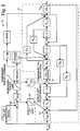
- Fig. 2 shows a detailed block diagram of a linearized closed loop transfer function for the blended missile autopilot 20 of Fig. 1d.
- the tail-controlled autopilot 21 is enclosed in the dashed box shown in Fig. 2, and the direct lift autopilot and blending scheme in accordance with the principles of the present invention is the balance of Fig. 2.
- the designs of the tail-controlled autopilot 21, the direct lift autopilot 22, and the blending mechanism are discussed below.
- the tail-controlled autopilot 21 operates to turn the tails 13 of the missile 11 to create pitching moment on the body of the missile 11, which generates missile angle-of-attack, resulting in lift. At the angle of attack where desired acceleration is achieved, the pitching moment generated by the tails 13 is equal and opposite to the pitching moment generated by the body of the missile 11, and the missile 11 is trimmed.
- a A CMD K ss K a V m M ⁇ N ⁇ - M ⁇ N ⁇ - s 2 N ⁇ s 3 + N ⁇ +M ⁇ K b - K a V m N ⁇ s 2 +(M ⁇ +(M ⁇ N ⁇ -M ⁇ N ⁇ )K b +K ⁇ M ⁇ s+(K a V m +K ⁇ )(M ⁇ N ⁇ - M ⁇ N ⁇ )
- M ⁇ q S ref d C m ⁇ I yy
- N ⁇ q S ref C n ⁇ m V m
- M ⁇ q S ref d C m ⁇ I yy
- N ⁇ q S ref C n ⁇ m V m
- s q S ref C n ⁇ m V m
- s q S ref C n ⁇ m V m
- s q S ref C n ⁇ m V
- Gains K a , K b , and K ⁇ are chosen to provide fast, well damped response.
- the bandwidth ( ⁇ ) of the autopilot 21 is set as large as stability allows.
- the blended missile autopilot 20 uses both tails 13 and thrusters 15 to generate force normal to the body of the missile 11, and balance opposing pitching moments, keeping the body of the missile 11 unrotated.
- the normal force is generated as fast as actuators for the tails 13 and thrusters 15 allow, much faster than the body of the missile 11 can rotate and produce lift, yielding an extremely fast autopilot 20.
- the tail-controlled autopilot 21 is used to control disturbance torques, such as those generated by wind gusts, or aerodynamic unbalances.
- K TAIL is a proportionality constant between commanded thrust and the direct lift portion of the tail commands.
- K TAIL is calculated to balance pitching moments due to tails 13 and thrusters 15.
- the tail deflection command provided by the direct lift autopilot 22 is summed with the deflection command of the tail-controlled autopilot tail 21 at location "A" in Fig. 2.
- the blending mechanism used to transition from the direct lift autopilot 22 to the tail-controlled autopilot 21 is designed to take full advantage of the fast response of direct lift autopilot 22.
- the blending mechanism comprises the use of a blending filter 24 coupled between the direct lift autopilot 22 and the tail-controlled autopilot 21. Normal force generated by the tails 13 and thrusters 15 is replaced by lift generated by the body of the missile 11 as fast as the tail-controlled autopilot 21 allows resulting in a smooth step response.
- the blending filter 24 also allows graceful degradation to the tail-controlled autopilot 21 when the commanded acceleration is greater than the tails 13 and thrusters 15 can deliver.
- the autopilot blending mechanism implemented in the present invention is to command the direct lift autopilot 22 to deliver precisely the commanded acceleration less what the tail controlled autopilot 21 delivers. This is accomplished in open loop fashion using the blending filter 24 illustrated in Fig. 2.
- the blending filter 24 is a very precise model of the response of the tail-controlled autopilot 21. Location "B" in Fig. 2 indicates where the estimate of the acceleration derived from the tail-controlled autopilot 21 is subtracted from the total acceleration command, leaving the net direct lift acceleration command.
- the blending filter 24 is a digital implementation of the desired closed loop response of the tail-controlled autopilot 21 given by Equation (1) above. Both poles and zeroes are modeled.
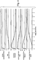
- Figs. 3 and 4 Linear, single plane simulation results for the first embodiment of the present invention are shown in Figs. 3 and 4.
- Fig. 3 shows the step response for a conventional tail-controlled autopilot 10 shown in Fig. 1a. Aerodynamics and flight conditions used are typical of ground and air launched tactical missiles 11.
- Fig. 4 shows the step response for the blended direct lift, tail-controlled autopilot 21 of Figs. 1d and 2. Flight conditions are identical. Comparing the first graph in Figs. 3 and 4, the benefits of direct lift are striking.
- the commanded acceleration is achieved in a fraction of the time required for the tail-controlled autopilot 10 of Fig. 1a.
- the fourth, fifth, and sixth graphs indicate the contributions to total acceleration from tails 13, thrusters 15, and body of the missile 11. A smooth transition from tail/thruster lift to body lift is effected by the blending mechanism.
- the thrust level returns to zero (third graph) and the thrusters 15 are available for further maneuvers.
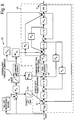
- Fig. 5 shows a blended direct lift, tail controlled autopilot 20 corresponding to the embodiment shown in Fig. 1e.
- the second embodiment of the direct lift autopilot 21 uses tails 13 and canards 14 (actuatable lateral force generating members 14) to generate lift, and balance opposing pitching moments, keeping the body of the missile 11 unrotated.
- the lift from control surfaces (tails 13 and canards 14) is generated as fast as their actuators allow, yielding an extremely fast autopilot 20.
- K tail is the proportionality constant between direct lift canard commands and the direct lift portion of the tail commands.
- K tail is calculated to balance pitching moments due to tails and canards.
- K C is the proportionality constant between direct lift acceleration and canard deflection:
- K C ⁇ C
- a DL 1 V m (N ⁇ K tail + N ⁇ C )
- the direct lift portion of the tail deflection command is summed with the tail-controlled autopilot tail deflection command at location "A" in Fig. 5.
- the blending mechanism used to transition from the direct lift autopilot 22 to the tail-controlled autopilot 21 comprises the blending filter 24 that is coupled between the direct lift autopilot 22 and the tail-controlled autopilot 21.
- Lift generated by the tails 13 and canards 14 is replaced by lift generated by the body of the missile 11 as fast as the tail-controlled autopilot 21 allows resulting in a smooth step response.
- the blending filter 24 also allows graceful degradation to the tail-controlled autopilot 21 when commanded accelerations are greater than tail and canard lift can generate.
- the implementation of autopilot blending is to command the direct lift autopilot 22 to precisely deliver the commanded acceleration less what the tail-controlled autopilot 21 delivers. This is accomplished in open loop fashion using the blending filter 24 illustrated in Fig. 5. Location "B" in Fig. 5 indicates where the estimate of the acceleration derived from the tail-controlled autopilot 21 is subtracted from the total acceleration command leaving the net direct lift acceleration command.
- the blending filter 24 is a digital implementation of the desired closed loop autopilot response given by Equation (1). Both poles and zeroes are modeled.
- Feedforward of the direct lift acceleration command into the tail-controlled autopilot 21 at location "C" in Fig. 5 causes the tail-controlled autopilot 21 to perform as if it is acting alone. Without the feedforward, the blending filter 24 could not properly match the tall controlled response, and the overall response of the autopilot 20 would be degraded.
- Fig. 6 shows a block diagram of an actuator model employed in the controller 12 of the autopilot 20 of Fig. 5 illustrating software position and rate limiters.
- Fig. 7 shows simulation results from a linear single plane simulation similar to those shown in Figs. 3 and 4.
- Fig. 7 shows a step response for the blended direct lift, tail-controlled autopilot 20 at flight conditions identical to those of Figs. 3 and 4. Aerodynamics have been modified to include canard effects. Comparing the first graphs of Figs. 3 and 7, the benefits of direct lift are clear. The commanded acceleration is achieved in a fraction of the time required for the tail-controlled configuration.
- the fourth, fifth, and sixth charts indicate the contributions to total acceleration from tails 13, canards 14, and body of the missile 11. A smooth transition from tail/canard lift to body lift is effected by the blending filter 24. Canard angle deflections are returned to zero (third graph) and the canards 14 are available for further maneuvers.
- blended missile autopilots comprising a direct lift missile autopilot to control canards or side thrusters and a tail-controlled autopilot to control tails have been disclosed. It is to be understood that the described embodiments are merely illustrative of some of the many specific embodiments which represent applications of the principles of the present invention. Clearly, numerous and other arrangements can be readily devised by those skilled in the art without departing from the scope of the invention.
Landscapes
- Engineering & Computer Science (AREA)
- General Engineering & Computer Science (AREA)
- Physics & Mathematics (AREA)
- Fluid Mechanics (AREA)
- Chemical & Material Sciences (AREA)
- Combustion & Propulsion (AREA)
- Control Of Position, Course, Altitude, Or Attitude Of Moving Bodies (AREA)
- Aiming, Guidance, Guns With A Light Source, Armor, Camouflage, And Targets (AREA)
Applications Claiming Priority (2)
| Application Number | Priority Date | Filing Date | Title |
|---|---|---|---|
| US08/463,603 US5590850A (en) | 1995-06-05 | 1995-06-05 | Blended missile autopilot |
| US463603 | 1995-06-05 |
Publications (2)
| Publication Number | Publication Date |
|---|---|
| EP0747655A2 true EP0747655A2 (de) | 1996-12-11 |
| EP0747655A3 EP0747655A3 (de) | 1998-12-02 |
Family
ID=23840675
Family Applications (1)
| Application Number | Title | Priority Date | Filing Date |
|---|---|---|---|
| EP96303437A Withdrawn EP0747655A3 (de) | 1995-06-05 | 1996-05-15 | Vielseitiger Autopilot für Raketen |
Country Status (6)
| Country | Link |
|---|---|
| US (1) | US5590850A (de) |
| EP (1) | EP0747655A3 (de) |
| JP (2) | JPH0933197A (de) |
| AU (1) | AU682992B2 (de) |
| CA (1) | CA2176626C (de) |
| IL (1) | IL118449A (de) |
Cited By (5)
| Publication number | Priority date | Publication date | Assignee | Title |
|---|---|---|---|---|
| US6402087B1 (en) * | 2000-07-11 | 2002-06-11 | The United States Of America As Represented By The Secretary Of The Army | Fixed canards maneuverability enhancement |
| WO2004097541A1 (en) * | 2003-04-29 | 2004-11-11 | Mass Consultants Limited | Control system for craft and a method of controlling craft |
| EP2876405A1 (de) * | 2013-11-20 | 2015-05-27 | MBDA Deutschland GmbH | Lenkflugkörper und Verfahren zum Lenken eines Lenkflugkörpers |
| CN110316400A (zh) * | 2019-07-22 | 2019-10-11 | 南京航空航天大学 | 一种鸭翼布局固定翼无人机直接升力控制方法 |
| US20210150918A1 (en) * | 2017-03-27 | 2021-05-20 | Gulfstream Aerospace Corporation | Aircraft flight envelope protection and recovery autopilot |
Families Citing this family (14)
| Publication number | Priority date | Publication date | Assignee | Title |
|---|---|---|---|---|
| US5631830A (en) | 1995-02-03 | 1997-05-20 | Loral Vought Systems Corporation | Dual-control scheme for improved missle maneuverability |
| US6308911B1 (en) | 1998-10-30 | 2001-10-30 | Lockheed Martin Corp. | Method and apparatus for rapidly turning a vehicle in a fluid medium |
| RU2181681C2 (ru) * | 1999-06-21 | 2002-04-27 | Государственное унитарное предприятие "Конструкторское бюро приборостроения" | Способ проверки качества функционирования рулевых приводов и автопилотов управляемых снарядов и устройство для его осуществления |
| RU2218550C2 (ru) * | 2002-01-09 | 2003-12-10 | Государственное унитарное предприятие "Конструкторское бюро приборостроения" | Способ определения аэродинамических характеристик управляемого снаряда в полете, способ определения угла атаки управляемого снаряда в полете, способ стабилизации углового положения управляемого снаряда и устройства для их осуществления |
| RU2246688C1 (ru) * | 2003-05-06 | 2005-02-20 | Государственное унитарное предприятие "Конструкторское бюро приборостроения" | Способ проверки газовой системы рулевого привода управляемого снаряда и устройство для его осуществления |
| US6921052B2 (en) * | 2003-11-28 | 2005-07-26 | The United States Of America As Represented By The Secretary Of The Army | Dragless flight control system for flying objects |
| IL162863A (en) * | 2004-07-05 | 2012-08-30 | Israel Aerospace Ind Ltd | Exo atmospheric intercepting system and method |
| GB0803282D0 (en) * | 2008-02-22 | 2008-04-02 | Qinetiq Ltd | Control of projectiles or the like |
| US8436283B1 (en) * | 2008-07-11 | 2013-05-07 | Davidson Technologies Inc. | System and method for guiding and controlling a missile using high order sliding mode control |
| DE102009016004A1 (de) * | 2009-04-02 | 2010-10-07 | Lfk-Lenkflugkörpersysteme Gmbh | Verfahren zum Abkoppeln eines Flugkörpers von einem Trägerluftfahrzeug |
| KR101050734B1 (ko) | 2010-12-21 | 2011-07-20 | 엘아이지넥스원 주식회사 | 카나드 조립체 및 이를 구비하는 비행체 |
| CN109424709B (zh) * | 2017-08-31 | 2022-02-15 | 上海微电子装备(集团)股份有限公司 | 一种线性模组及其工作方法 |
| JP7465531B2 (ja) * | 2020-07-17 | 2024-04-11 | 国立研究開発法人宇宙航空研究開発機構 | ロケット制御システム、及びロケットの着陸動作の制御方法 |
| US12050085B2 (en) * | 2022-12-13 | 2024-07-30 | Bae Systems Information And Electronic Systems Integration Inc. | Ballistic guidance system |
Citations (3)
| Publication number | Priority date | Publication date | Assignee | Title |
|---|---|---|---|---|
| JPS63290400A (ja) | 1987-05-20 | 1988-11-28 | 防衛庁技術研究本部長 | 双操舵型飛しょう体の操舵方法 |
| JPH04316994A (ja) | 1991-04-17 | 1992-11-09 | Tech Res & Dev Inst Of Japan Def Agency | 双操舵飛しょう体の制御方法 |
| JPH07133999A (ja) | 1993-11-09 | 1995-05-23 | Nissan Motor Co Ltd | 飛翔体の姿勢制御装置 |
Family Cites Families (16)
| Publication number | Priority date | Publication date | Assignee | Title |
|---|---|---|---|---|
| US5439188A (en) * | 1964-09-04 | 1995-08-08 | Hughes Missile Systems Company | Control system |
| US4171115A (en) * | 1977-12-12 | 1979-10-16 | Sperry Rand Corporation | Stability augmentation system for relaxed static stability aircraft |
| DE3047389A1 (de) * | 1979-12-17 | 1981-09-17 | Motorola, Inc., 60196 Schaumburg, Ill. | Flugkoerper |
| DE3317583C2 (de) * | 1983-05-13 | 1986-01-23 | Messerschmitt-Bölkow-Blohm GmbH, 8012 Ottobrunn | Vorrichtung mit einer von einer Treibmittelquelle versorgten Düsenanordnung |
| GB2208017B (en) * | 1983-11-25 | 1989-07-05 | British Aerospace | Guidance systems |
| US4624424A (en) * | 1984-11-07 | 1986-11-25 | The Boeing Company | On-board flight control drag actuator system |
| DE3738580A1 (de) * | 1987-11-13 | 1989-06-01 | Diehl Gmbh & Co | Gelenktes artillerieprojektil mit flugbahnregler |
| GB8803164D0 (en) * | 1988-02-11 | 1988-08-24 | British Aerospace | Reaction control system |
| US5058836A (en) * | 1989-12-27 | 1991-10-22 | General Electric Company | Adaptive autopilot |
| US5094406A (en) * | 1991-01-07 | 1992-03-10 | The Boeing Company | Missile control system using virtual autopilot |
| US5088658A (en) * | 1991-03-20 | 1992-02-18 | Raytheon Company | Fin command mixing method |
| US5259569A (en) * | 1992-02-05 | 1993-11-09 | Hughes Missile Systems Company | Roll damper for thrust vector controlled missile |
| RU2021577C1 (ru) * | 1992-06-30 | 1994-10-15 | Машиностроительное Конструкторское Бюро "Факел" | Способ управления снарядом |
| FR2694390B1 (fr) * | 1992-07-28 | 1994-09-16 | Thomson Csf | Procédé de commande d'un missile minimisant sa distance de passage par rapport à une cible agile, et dispositif de mise en Óoeuvre. |
| JP3286969B2 (ja) * | 1992-09-14 | 2002-05-27 | 防衛庁技術研究本部長 | 飛翔体のオートパイロット |
| DE69520981T2 (de) * | 1994-05-20 | 2002-04-04 | Trw Inc., Lyndhurst | Verfahren und Vorrichtung zur Regelung eines elektrischen Hilfskraftlenksystems mit einem adaptiven Übergangsfilter für das Drehmoment |
-
1995
- 1995-06-05 US US08/463,603 patent/US5590850A/en not_active Expired - Lifetime
-
1996
- 1996-05-15 CA CA002176626A patent/CA2176626C/en not_active Expired - Fee Related
- 1996-05-15 AU AU52274/96A patent/AU682992B2/en not_active Ceased
- 1996-05-15 EP EP96303437A patent/EP0747655A3/de not_active Withdrawn
- 1996-05-28 IL IL11844996A patent/IL118449A/xx unknown
- 1996-06-05 JP JP8143062A patent/JPH0933197A/ja active Pending
-
1999
- 1999-06-03 JP JP11156843A patent/JP2000131000A/ja not_active Withdrawn
Patent Citations (3)
| Publication number | Priority date | Publication date | Assignee | Title |
|---|---|---|---|---|
| JPS63290400A (ja) | 1987-05-20 | 1988-11-28 | 防衛庁技術研究本部長 | 双操舵型飛しょう体の操舵方法 |
| JPH04316994A (ja) | 1991-04-17 | 1992-11-09 | Tech Res & Dev Inst Of Japan Def Agency | 双操舵飛しょう体の制御方法 |
| JPH07133999A (ja) | 1993-11-09 | 1995-05-23 | Nissan Motor Co Ltd | 飛翔体の姿勢制御装置 |
Non-Patent Citations (2)
| Title |
|---|
| INNOCENTI M., THUKRAL A.: "Simultaneous Reaction Jet and Aerdoynamic Control of Missile Systems", AIAA, 1993, pages 347 - 354, XP002907507 |
| WEIL R.D ET AL: "Blended Aero & Reaction Jet Missile Autopilot Design Using VSS Techniques", IEEE, PROCEEDINGS OF THE 30TH CONFERENCE ON DECISION AND CONTROL, 1991, BRIGHTON UK, pages 2028 - 2029, XP002907508 |
Cited By (10)
| Publication number | Priority date | Publication date | Assignee | Title |
|---|---|---|---|---|
| US6402087B1 (en) * | 2000-07-11 | 2002-06-11 | The United States Of America As Represented By The Secretary Of The Army | Fixed canards maneuverability enhancement |
| WO2004097541A1 (en) * | 2003-04-29 | 2004-11-11 | Mass Consultants Limited | Control system for craft and a method of controlling craft |
| EP2876405A1 (de) * | 2013-11-20 | 2015-05-27 | MBDA Deutschland GmbH | Lenkflugkörper und Verfahren zum Lenken eines Lenkflugkörpers |
| US20210150918A1 (en) * | 2017-03-27 | 2021-05-20 | Gulfstream Aerospace Corporation | Aircraft flight envelope protection and recovery autopilot |
| US11580865B2 (en) * | 2017-03-27 | 2023-02-14 | Gulfstream Aerospace Corporation | Aircraft flight envelope protection and recovery autopilot |
| US20230154343A1 (en) * | 2017-03-27 | 2023-05-18 | Gulfstream Aerospace Corporation | Aircraft flight envelope protection and recovery autopilot |
| US12033526B2 (en) * | 2017-03-27 | 2024-07-09 | Gulfstream Aerospace Corporation | Aircraft flight envelope protection and recovery autopilot |
| US20240363013A1 (en) * | 2017-03-27 | 2024-10-31 | Gulfstream Aerospace Corporation | Aircraft flight envelope protection and recovery autopilot |
| CN110316400A (zh) * | 2019-07-22 | 2019-10-11 | 南京航空航天大学 | 一种鸭翼布局固定翼无人机直接升力控制方法 |
| CN110316400B (zh) * | 2019-07-22 | 2022-04-15 | 南京航空航天大学 | 一种鸭翼布局固定翼无人机直接升力控制方法 |
Also Published As
| Publication number | Publication date |
|---|---|
| JP2000131000A (ja) | 2000-05-12 |
| AU5227496A (en) | 1996-12-19 |
| CA2176626C (en) | 1999-03-16 |
| JPH0933197A (ja) | 1997-02-07 |
| US5590850A (en) | 1997-01-07 |
| AU682992B2 (en) | 1997-10-23 |
| EP0747655A3 (de) | 1998-12-02 |
| IL118449A0 (en) | 1996-09-12 |
| IL118449A (en) | 2000-08-13 |
| CA2176626A1 (en) | 1996-12-06 |
Similar Documents
| Publication | Publication Date | Title |
|---|---|---|
| US5590850A (en) | Blended missile autopilot | |
| US5322243A (en) | Separately banking maneuvering aerodynamic control surfaces, system and method | |
| US5582364A (en) | Flyable folding fin | |
| KR102161845B1 (ko) | 엘리본 제어 시스템 | |
| EP0622604B1 (de) | Drehbar angeordneter und mittels eines flexiblen Bandes hergestellter Tragflügel | |
| US5259569A (en) | Roll damper for thrust vector controlled missile | |
| EP0928269B1 (de) | Dreh-und steuerungsvorrichtung für fahrzeuge | |
| US5366176A (en) | Feedback-stabilized aerodynamically overbalanced lifting/control surface for aircraft | |
| JPS58500493A (ja) | 空中または水中ミサイル用方向制御装置 | |
| US20080029641A1 (en) | Three Axis Aerodynamic Control of Guided Munitions | |
| Rogers et al. | Design of a roll-stabilized mortar projectile with reciprocating canards | |
| EP2223035B1 (de) | Durch eine drehfeder unterstützter aktuator für ein flugkörpersystem | |
| US20230243628A1 (en) | Command mixing for roll stabilized guidance kit on gyroscopically stabilized projectile | |
| EP0065529B1 (de) | Raketenfahrzeug | |
| US4643374A (en) | Steering apparatus for a flying body | |
| US5875993A (en) | Flight control of an airborne vehicle at low velocity | |
| WO2024076290A1 (en) | Single-wing rotorcraft with multiple flight modes | |
| Chatterji et al. | Modified velocity pursuit guidance law with crosswind correction formissiles against surface targets | |
| Butler | Smart Projectile Performance Augmentation Using an Articulating Nose | |
| Nugroho | Extending Range and Minimizing Turn Radius for a Missile Rocket | |
| Morgan | Aerospace Vehicle Steering with Uncontrolled Axial Acceleration | |
| Anderson et al. | Design of a Ground-Launched Ballistic Missile Interceptor Using a Genetic Algorithm | |
| JPH06300499A (ja) | 飛しょう体 | |
| Smith | A comparison of the control problems of missiles and manned aircraft |
Legal Events
| Date | Code | Title | Description |
|---|---|---|---|
| PUAI | Public reference made under article 153(3) epc to a published international application that has entered the european phase |
Free format text: ORIGINAL CODE: 0009012 |
|
| AK | Designated contracting states |
Kind code of ref document: A2 Designated state(s): DE FR GB IT |
|
| RAP1 | Party data changed (applicant data changed or rights of an application transferred) |
Owner name: RAYTHEON COMPANY |
|
| PUAL | Search report despatched |
Free format text: ORIGINAL CODE: 0009013 |
|
| AK | Designated contracting states |
Kind code of ref document: A3 Designated state(s): DE FR GB IT |
|
| 17P | Request for examination filed |
Effective date: 19990510 |
|
| TPAD | Observations filed by third parties |
Free format text: ORIGINAL CODE: EPIDOS TIPA |
|
| 17Q | First examination report despatched |
Effective date: 20040824 |
|
| TPAC | Observations filed by third parties |
Free format text: ORIGINAL CODE: EPIDOSNTIPA |
|
| STAA | Information on the status of an ep patent application or granted ep patent |
Free format text: STATUS: THE APPLICATION IS DEEMED TO BE WITHDRAWN |
|
| 18D | Application deemed to be withdrawn |
Effective date: 20050304 |