EP0747776A2 - Couvercles d'extrémités pour tambours cylindriques - Google Patents
Couvercles d'extrémités pour tambours cylindriques Download PDFInfo
- Publication number
- EP0747776A2 EP0747776A2 EP96304273A EP96304273A EP0747776A2 EP 0747776 A2 EP0747776 A2 EP 0747776A2 EP 96304273 A EP96304273 A EP 96304273A EP 96304273 A EP96304273 A EP 96304273A EP 0747776 A2 EP0747776 A2 EP 0747776A2
- Authority
- EP
- European Patent Office
- Prior art keywords
- drum
- cylindrical
- expandable body
- hub
- urging member
- Prior art date
- Legal status (The legal status is an assumption and is not a legal conclusion. Google has not performed a legal analysis and makes no representation as to the accuracy of the status listed.)
- Granted
Links
Images



Classifications
-
- G—PHYSICS
- G03—PHOTOGRAPHY; CINEMATOGRAPHY; ANALOGOUS TECHNIQUES USING WAVES OTHER THAN OPTICAL WAVES; ELECTROGRAPHY; HOLOGRAPHY
- G03G—ELECTROGRAPHY; ELECTROPHOTOGRAPHY; MAGNETOGRAPHY
- G03G15/00—Apparatus for electrographic processes using a charge pattern
- G03G15/75—Details relating to xerographic drum, band or plate, e.g. replacing, testing
- G03G15/751—Details relating to xerographic drum, band or plate, e.g. replacing, testing relating to drum
Definitions
- the present invention relates to photoconductive drums used in electrophotographic printing machines, and more particularly, the invention relates to end caps mounted in the photoconductive drum.
- a photoconductive drum is a cylindrical substrate used in an electrophotographic printing machine.
- the cylindrical substrate is coated with one or more layers of a photoconductive material, i.e., a material whose electrical conductivity changes upon illumination.
- the photoconductive drum or member includes, for example, an aluminum cylinder having a thin layer of a photoconductive organic compound thereon.
- electrophotographic printing an electrical potential is applied across the photoconductive layer and then exposed to light of an image.
- the electrical potential of the photoconductive layer decays at the portions irradiated by the light, leaving a distribution of electrostatic charge corresponding to the dark areas of the projected image.
- the electrostatic latent image is made visible by development with a suitable powder.
- the cylindrical substrate must meet precise tolerance standards and adhere well to photoconductive insulative layers applied thereto.
- the aluminum drums utilized as a support substrate are relatively expensive and often require replacement due to wear prior to the need to replace the photoconductive insulating layer. For example rapid wear is caused by spacing shoes riding on the surface of the ends of the aluminum drums.
- reconditioning of the aluminum drums, including lathing and polishing is a necessary prerequisite to prepare the substrate to receive a coating of the photoconductive layer or layers.
- Aluminum drums may necessarily be thick in order to achieve adequate rigidity to meet the stringent tolerance requirements. Heavy drums, however, require more powerful drive systems and rugged clutches to overcome high inertia characteristics.
- the end cap has an outer diameter which is in sliding engagement with an internal lip on the photoconductive drum. Both the hub diameter and the drum inner diameter require close tolerances and low runout to assure the required low assembly runout.
- US-A-4,561,763 to Basch discloses a drum support hub which includes a flexible collet and is fitted between the inner diameter of the drum and an internal lip on the hub.
- the resilient fingers on the collet provided some alleviation in the tolerance in the required tolerances of the drum inner diameter and the hub counter bore.
- the collet was molded of a plastic material and consequently had only minimal gripping power to hold the hub to the photoreceptive drum, requiring still unacceptably close tolerances to maintain the hub assembly radial runout requirements.
- Photoconductive drum end caps consist of a generally cylindrical drum having end caps with an outer diameter which is slidingly fitted within the bore of the drum. End caps are generally bonded to the drum with an adhesive. With this design, the drum inside diameter and the outer diameter of the hub require very close tolerances. Further, the use of adhesives may require a delay in the assembly process for the adhesive to cure prior to subsequent assembly.
- US-A-5,357,321 discloses a drum supporting hub including a disc shaped member having a circular periphery. A hole extends axially through the center of the disc shaped member and a long thin electrically conductive resilient s-shaped member is trapped between flared edges and an axle shaft and the ends of the s-shaped member contact the inner periphery of the disc shaped member.
- US-A-5,151,737 discloses a hollow cylindrical shell having an axial slit.
- Axial ribs extend inwardly from the shell.
- Conical wedges are fitted to the ends of the shell and the conical surface of the wedges contact chamfers on the ribs.
- a shaft is slidably fitted to an axial opening in the wedges.
- a nut on an end of the shaft is used to draw the wedges together causing the shell to expand.
- US-A-4,400,077 discloses a photosensitive drum assembly having a cylindrical drum and two disc shaped flanges positioned on the ends of the drum.
- the flanges each include a lip which is closely fitted to the external periphery of the drum.
- Connecting rods interconnect the flanges.
- US-A-4,120,576 discloses a drum support apparatus for supporting a cylindrical drum.
- the apparatus includes a pair of hubs each having a central stem.
- a shaft interconnects the hubs and has a loosely fitted tube over the shaft.
- the periphery of the stem fits with the inner periphery of the tube.
- Tabs on the shaft interconnect with a slot in the stem.
- US-A-4,105,345 discloses a drum support assembly including a cylindrical drum having spaced apart internal grooves and a pair of hubs.
- the hubs each have four equally spaced radially sliding lock plates with an outer edge which matingly fits into the grooves.
- a centrally located shaft is secured to the hubs and interconnects them.
- US-A-4,040,157 discloses a drum support assembly a cylindrical hub and two conical shaped hubs.
- the hubs include equally spaced lobes on the periphery of the hubs which mate with an internal periphery on the ends of the hub.
- a shaft is fitted to the center of the hubs and three equally spaced tie rods interconnect the hubs.
- US-A-3,994,053 discloses a drum support assembly a cylindrical hub and two conical shaped hubs.
- the hubs include equally spaced lobes on the periphery of the hubs which mate with an internal periphery on the ends of the hub.
- a shaft is fitted to the center of the hubs and three equally spaced tie rods interconnect the hubs.
- a hub for supporting a tube.
- the hub includes an expandable body adapted to be mounted at least partially in the tube and a resilient urging member.
- the urging member has at least a portion of the urging member internal to the body to expand the body so that a portion of the body contacts the tube.
- a photoconductive member in accordance with another aspect of the present invention, there is provided a photoconductive member.
- the member includes a drum which has a photoconductive material coated on the drum and a hub for supporting a tube.
- the hub includes an expandable body adapted to be mounted at least partially in the tube and a resilient urging member.
- the urging member has at least a portion of the urging member internal to the body to expand the body so that a portion of the body contacts the tube.
- FIG. 6 schematically depicts the various components of an electrophotographic printing machine incorporating the present invention therein.
- the printing machine shown employs a photoconductive drum 16, which has a photoconductive surface 28 deposited on a conductive substrate.
- Drum 16 moves in the direction of arrow 18 to advance successive portions thereof sequentially through the various processing stations disposed about the path of movement thereof.
- Motor 26 rotates drum 16 to advance drum 16 in the direction of arrow 18.
- Drum 16 is coupled to motor 26, by suitable means such as a drive.
- a corona generating device 30 charges the drum 16 to a selectively high uniform electrical potential.
- the electrical potential is normally opposite in sign to the charge of the toner. Depending on the toner chemical composition, the potential may be positive or negative. Any suitable control, well known in the art, may be employed for controlling the corona generating device 30.
- a document 34 to be reproduced is placed on a platen 22, located at imaging station B, where it is illuminated in a known manner by a light source, such as a lamp 24 with a photo spectral output matching the photo spectral sensitivity of the photoconductor and a reflector 25.
- a light source such as a lamp 24 with a photo spectral output matching the photo spectral sensitivity of the photoconductor and a reflector 25.
- the document thus exposed is imaged onto the drum 16 by a system of mirrors (not shown) and lens 27, as shown.
- the optical image selectively discharges surface 28 of the drum 16 in an image configuration whereby an electrostatic latent image 32 of the original document is recorded on the drum 16 at the imaging station B.
- a development system or unit 36 advances developer materials into contact with the electrostatic latent images.
- the developer unit 36 includes a device to advance developer material into contact with the latent image and develop the charged image areas of the photoconductive surface 28.
- This developer unit contains black developer, for example, having a triboelectric charge such that the black toner is urged towards charged areas of the latent image by the electrostatic field existing between the photoconductive surface and the electrically biased developer rolls 42 in the developer unit which are connected to bias power supply (not shown).
- a sheet of support material 58 is moved into contact with the toner image at transfer station D.
- the sheet of support material 58 is advanced to transfer station D by conventional sheet feeding apparatus, not shown, which directs the advancing sheet of support material into contact with the photoconductive surface of drum 16 in a timed sequence so that the toner powder image developed thereon contacts the advancing sheet of support material at transfer station D.
- Transfer station D includes a corona generating device 60 which sprays ions of a suitable polarity onto the backside of sheet 58. This attracts the toner powder image from the drum 16 to sheet 58. After transfer, the sheet continues to move, in the direction of arrow 62, onto a conveyor (not shown) which advances the sheet to fusing station E.
- Fusing station E includes a fuser assembly 64 which permanently affixes the transferred powder image to sheet 58.
- fuser assembly 64 comprises a heated fuser roller 66 and a pressure roller 68.
- Sheet 58 passes between fuser roller 66 and pressure roller 68 with the toner powder image contacting fuser roller 66. In this manner, the toner powder image is permanently affixed to sheet 58. After fusing, the sheet 58 is advanced to a catch tray, not shown, for subsequent removal from the printing machine by the operator.
- the cleaning station F includes a blade 74.
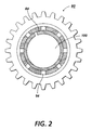
- the end cap 80 includes an expandable body 82 and a resilient urging member 84 located at least partially inside the expandable body 82.
- the expandable body 82 includes at least a cylindrical portion 86 which is expandable.
- the expandable body 82 may also include a disk shaped portion 90 extending from a first end 92 of the cylindrical portion 86 of the expandable body 82.
- the cylindrical portion 86 has a generally tubular shape.
- the cylindrical portion 86 may be made of any suitable durable material and may be made of an expandable natural or synthetic material such as a rubber or synthetic rubber, but preferably is made of a material with limited ability to expand, such as a plastic, for example, polycarbonate.
- voids or apertures in preferably the form of slots 94 extend axially from a second open end 96 of the cylindrical portion 86.
- the slots 94 are preferably made of a width Ws and a length Ls sufficient to provide the expanding capability necessary for the cylindrical portion 86. While the invention may be practiced with as few as one slit when using a generally non-expandable material, preferably a plurality of, for example 8, equally spaced apart slots 94 are spaced about the cylindrical portions 86.
- the disk shaped portion 90 may be distinct from cylindrical portion 86, or preferably be molded integrally with the cylindrical portion 86.
- the disk shaped portion 90 is thus preferably molded of a plastic material, for example, filled polycarbonate, preferably the same material as the cylindrical portion 86.
- the disk shaped portion preferably includes a central cap portion 98 which serves to enclose the first end 92 of the cylindrical portion 86 and to prevent contamination from entering a cavity 100 formed within the cylindrical portion 86 of the expandable body 82.
- a gear 102 is located on the disk shaped portion 90.
- the gear 102 may be made of a separate material from the disk shaped portion 90, or as shown in Figure 1 and as preferred, be integral with the disk shaped portion 90.
- the gear 102 may be any suitable force transmitting gear but preferably is a helical gear to provide for an axial bias to the hub 80.
- the disk shaped portion 90 preferably provides for the positioning of the hub 80 and, as shown in Figure 1, the disk shaped portion 90 includes a centrally located aperture 103 through which a shaft (not shown) may slidably fit to provide for the positioning of the hub 80.
- the resilient urging member 84 may be any suitable member capable of exerting a radially outward force on inner periphery 104 of the cylindrical portion 86 of the expandable body 82. As shown in Figure 1, the resilient urging member 84 is in the form of a spring. The spring 84 is placed in the cavity 100 of the cylindrical portion 86 of the hub 80 and is positioned in a compressible position within the cylindrical portion 86 such that a portion of the member 84 applies a force against the inner periphery 104 of the cylindrical portion 86.
- the resilient urging member 84 may be in the form of a split ring made of a resilient material, for example, spring steel.
- An internal groove 106 may be formed in the inner periphery 104 of the cylindrical portion 86.
- the internal groove 106 has a width WG which is slightly larger than the width WR of the ring 84.
- the internal groove 106 serves to contain the ring 84 within the cylindrical portion 86.
- the ring 84 has a free unassembled diameter DF which is slightly larger than the inner diameter DG of the groove.
- the ring 84 exerts a radially outward force on the inner periphery 104 the cylindrical portion 86 of the expandable body 82 causing outer periphery 110 of the cylindrical portion 86 to expand from a first unstrained position 112 when the ring has not been inserted to a second expanded position 114 upon insertion of the ring 84.
- the eight slots 94 are shown equally spaced about the cylindrical portion 86 of the expandable body 82.
- the ring 84 is shown located in the internal groove 106 of the expandable body 82.
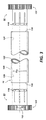
- the drum 16 typically includes a cylindrical substrate 120 typically made of aluminum upon which a photosensitive material 122 is applied.
- a first hub 124 is fitted into the inner periphery 126 of the drum 16 at first end 130 of the drum 16 while a second hub 132 is fitted into the inner periphery 126 at a second end 134 of the drum 16.
- a chamfer 116 is located between the second end 96 of the cylindrical portion 86 and the outer periphery 110 of the cylindrical portion 86.
- chamfer 116 has a length L c and an entry angle ⁇ sufficient to provide for an efficient and damage free insertion of the hubs 80 into the drum 16.
- the hubs 80 have a hub diameter D H with the ring 84 installed within the hub 80 which is slightly larger than the inner diameter D D of the drum 16 in order to secure the hubs 80 to the drum 16.
- the surface roughness of the outer periphery 110 and the inner periphery 126 should be accurately controlled.
- the drum 16 is machined to a controlled finish.
- Molding the hub 80 should provide the outer periphery 110 of the hub 80 with an accurate surface finish to obtain the required coefficient of friction.
- a friction enhancing material i.e. elastomer, or a friction enhancing ring may be inserted between the inner periphery 126 and the outer periphery 110.
- the hub 280 includes an expandable body 282 which is similar to expandable body 82 of end cap 80 and a resilient urging member 284 which is similar to urging member 84 of end cap 80.
- the resilient urging member 284 is located at least partially inside the expandable body 282.
- the expandable body 282 includes a cylindrical portion 286 which is expandable.
- the expandable body may also include a disk shaped portion 290 which extends from a first end 292 of the cylindrical portion 286 of expandable body 282.
- the cylindrical portion 286 has a generally tubular shape somewhat similar to that of cylindrical portion 86 of end cap 80.
- the cylindrical portion 286 may be made of any suitable durable material and may be made of an expandable natural or synthetic material such as rubber or synthetic rubber, but preferably is made of a material with limited ability to expand, such as a plastic, for example, polycarbonate.
- openings preferably in the form of slots 294 extend axially from a second open end 296 of the cylindrical portion 286, similarly to cylindrical portion 86 of end cap 80.
- the slots 294, however, have a width W SL which is significantly wider than the slots 94 of end cap 80. Fingers 260 are thus formed between adjacent slots 294.
- the slots 294 preferably are made with a width W SL and a length L SL sufficient to provide for the expanding capacity necessary for the cylindrical portion 286.
- the fingers 260 have a width W F which is approximately equal to the width W SL of the slots 294. While the invention may be practiced with as few as one slot, similar to end cap 80, when using a generally non-expandable material, preferably, a plurality of, for example, 8 equally spaced apart slots 294 are used.
- the expandable body 286 also includes a cylindrically shaped portion 290 which is similar to cylindrical shaped portion 90 of end cap 80.
- the cylindrical shaped portion 290 includes a central aperture or opening 203 which is similar to opening 103 of end cap 80.
- the disk shaped portion 290 also includes a gear 202 similar to gear 102 of end cap 80, except that gear 202 as shown is a spur gear, although a helical gear as in gear 102 of end cap 80 may likewise be suitable for the practice of the invention.
- the disk shaped portion 290 preferably includes at least one opening 264 which extends axially through the hub 280.
- the resilient urging member 28 unlike the resilient urging member 84 of the end cap 80, is made of a compressible material.
- the urging member 84 may be made of an elastomer, for example, synthetic rubber.
- the urging member 284 may have any suitable shape, but is typically in the form of a ring.
- the ring 284 is placed in cavity 200 of the cylindrical portion 286 of the end cap 280.
- the compressible urging member 284 includes lands 274 which extend radially outwardly from the member 284. Recesses 276 are formed between adjacent lands 274.
- the member 284 When inserting the compressible urging member 284 to the expandable body 282, the member 284 is so aligned such that lands 274 are in line with slots 294 and the recesses 276 are in line with fingers 260.
- the lands 274 upon insertion of the urging member 284 are located in the slots 294 while the fingers 260 are located in the recesses 276.
- the lands 274 have a width W L which is slightly smaller than the width W SL of the slots while the recesses 276 have a width W RE which is slightly larger than the width W F of the fingers 260.
- the outer periphery 272 of the urging member 284 has a diameter D CM which is slightly larger than the diameter D FG of the fingers 260 of the body 282.
- the member 284 at the recesses 276 interferes and extends outwardly the fingers 260 to provide for a diameter D FG which when expanded is larger than diameter D TU of the inner periphery 270 of the drum 16.
- the urging member 284 thus upon insertion into the expandable body 286 and thereafter into the inner periphery 270 of the drum 16 causes both the lands 274 of the member 284 as well as the fingers 260 of the body 282 to interfere and hold against the inner periphery 270.
- the openings 264 in disk shaped portion 290 which may be a single opening but preferably are four equally spaced openings, are designed in the end cap 280 so that a mounting tool can push directly through the body 282 and onto the urging member 284 to avoid spring back of the body 282 during assembly.
- the elastomer material of the member 284 provides a higher degree of friction on the aluminum compared to the body 82 of the end cap 80.
- the higher friction for the end cap 280 permits the reduction of interference between the urging member 284 and the drum 16 resulting in reduced pressure on the drum 16 and reduced flaring of the drum 16.
- the spring biased hub of the present invention provides for easy insertion and removal of the hubs as well as a simplified assembly and disassembly process.
- the spring bias against the internal periphery of the expandable hub provides for a transmission of torque over a wide range of temperatures as well as a self compensation for differences in the thermal expansion coefficients of the different materials.
- the absence of an adhesive in the hub 80 eliminates the use of potentially hazardous chemicals and provides for easy and simple disassembly of the ring from the hub and for an inexpensive and simple remanufacture of the hub 80.
Landscapes
- Physics & Mathematics (AREA)
- General Physics & Mathematics (AREA)
- Discharging, Photosensitive Material Shape In Electrophotography (AREA)
- Electrophotography Configuration And Component (AREA)
Applications Claiming Priority (2)
| Application Number | Priority Date | Filing Date | Title |
|---|---|---|---|
| US483000 | 1995-06-07 | ||
| US08/483,000 US5579093A (en) | 1995-06-07 | 1995-06-07 | Resiliently biased end caps for photoconductive drums |
Publications (3)
| Publication Number | Publication Date |
|---|---|
| EP0747776A2 true EP0747776A2 (fr) | 1996-12-11 |
| EP0747776A3 EP0747776A3 (fr) | 1997-03-19 |
| EP0747776B1 EP0747776B1 (fr) | 2002-01-30 |
Family
ID=23918237
Family Applications (1)
| Application Number | Title | Priority Date | Filing Date |
|---|---|---|---|
| EP96304273A Expired - Lifetime EP0747776B1 (fr) | 1995-06-07 | 1996-06-07 | Couvercles d'extrémités pour tambours cylindriques |
Country Status (4)
| Country | Link |
|---|---|
| US (1) | US5579093A (fr) |
| EP (1) | EP0747776B1 (fr) |
| JP (1) | JPH08335007A (fr) |
| DE (1) | DE69618855T2 (fr) |
Cited By (1)
| Publication number | Priority date | Publication date | Assignee | Title |
|---|---|---|---|---|
| GB2323559A (en) * | 1997-03-22 | 1998-09-30 | Xerox Corp | End cap mounting assembly for photoreceptor drum |
Families Citing this family (12)
| Publication number | Priority date | Publication date | Assignee | Title |
|---|---|---|---|---|
| DE69630647T2 (de) * | 1995-09-26 | 2004-09-30 | Sharp K.K. | Antriebsvorrichtung für lichtempfindliche Trommel |
| US5983055A (en) * | 1996-03-19 | 1999-11-09 | Sharp Kabushiki Kaisha | Photosensitive element for electrophotography |
| JP4038932B2 (ja) * | 1999-05-11 | 2008-01-30 | 富士電機デバイステクノロジー株式会社 | 電子写真用感光体 |
| JP3968940B2 (ja) * | 2000-03-03 | 2007-08-29 | 富士ゼロックス株式会社 | 円筒体用軸受部材の固定方法、円筒体用軸受部材の固定構造、軸受部材付き電子写真感光体、プリントカートリッジ及び画像形成装置 |
| US6301458B1 (en) * | 2000-08-03 | 2001-10-09 | Toshiba Tec Kabushiki Kaisha | Image forming apparatus |
| US6490426B1 (en) | 2000-11-03 | 2002-12-03 | Xerox Corporation | Modular imaging member flange assembly |
| US6698487B2 (en) * | 2000-11-15 | 2004-03-02 | Xyron, Inc. | Master processing apparatus |
| EP1630625A4 (fr) * | 2003-05-22 | 2012-10-03 | Mitsubishi Chem Corp | Tambour a corps photosensible, procede et dispositif d'assemblage de ce tambour, et dispositif de formation d'images utilisant ce tambour |
| KR100475575B1 (ko) * | 2003-06-11 | 2005-03-14 | 삼성전자주식회사 | 화상형성장치 |
| KR100542363B1 (ko) | 2004-04-07 | 2006-01-10 | 삼성전자주식회사 | 화상형성장치의 감광드럼 |
| US7346292B2 (en) * | 2005-07-28 | 2008-03-18 | Static Control Components, Inc. | Systems and methods for remanufacturing imaging components |
| CN121285521A (zh) * | 2023-06-01 | 2026-01-06 | 信诺工业集团有限责任公司 | 用于无芯膜卷的可重复使用的膜芯 |
Family Cites Families (18)
| Publication number | Priority date | Publication date | Assignee | Title |
|---|---|---|---|---|
| US2891301A (en) * | 1952-08-26 | 1959-06-23 | Wooster Brush Co | Paint applicator |
| US3695757A (en) * | 1969-02-27 | 1972-10-03 | Xerox Corp | Xerographic plate |
| US3994053A (en) * | 1976-01-08 | 1976-11-30 | Xerox Corporation | Drum support apparatus |
| US4040157A (en) * | 1976-01-08 | 1977-08-09 | Xerox Corporation | Drum support apparatus |
| US4105345A (en) * | 1976-02-27 | 1978-08-08 | Xerox Corporation | Expandable photoreceptor endbells |
| US4120576A (en) * | 1977-04-04 | 1978-10-17 | Xerox Corporation | Drum support apparatus |
| DE2717055A1 (de) * | 1977-04-18 | 1978-10-19 | Siemens Ag | Einrichtung zum lagern einer als zwischentraeger in einem nach dem elektrostatischen prinzip arbeitenden druck- oder kopiergeraet verwendeten trommel |
| JPS5782879A (en) * | 1980-11-12 | 1982-05-24 | Mita Ind Co Ltd | Photosensitive drum of electrostatic copier |
| JPS5886553A (ja) * | 1981-11-19 | 1983-05-24 | Konishiroku Photo Ind Co Ltd | ドラム状像担持体部材 |
| US4621919A (en) * | 1983-07-13 | 1986-11-11 | Canon Kabushiki Kaisha | Metal drum and image holding member using the same |
| US4561763A (en) * | 1984-08-03 | 1985-12-31 | Xerox Corporation | Drum support apparatus |
| US4878085A (en) * | 1987-04-28 | 1989-10-31 | Storage Technology Corporation | Cylinder and hub locking method and apparatus |
| JPH089732Y2 (ja) * | 1989-07-11 | 1996-03-21 | 三田工業株式会社 | 感光体ドラム |
| US5151737A (en) * | 1990-06-04 | 1992-09-29 | Eastman Kodak Company | Photoconductive drum having expandable mount |
| FR2664713B1 (fr) * | 1990-07-13 | 1994-07-29 | Canon Kk | Cartouche de traitement et appareil de formation d'images l'utilisant. |
| US5357321A (en) * | 1994-01-04 | 1994-10-18 | Xerox Corporation | Drum supporting hub and drum assembly |
| US5465138A (en) * | 1994-08-29 | 1995-11-07 | Xerox Corporation | Development apparatus having a spincast roll assembly |
| US5461464A (en) * | 1994-11-03 | 1995-10-24 | Xerox Corporation | Photoreceptor assembly |
-
1995
- 1995-06-07 US US08/483,000 patent/US5579093A/en not_active Expired - Lifetime
-
1996
- 1996-05-28 JP JP8133212A patent/JPH08335007A/ja not_active Withdrawn
- 1996-06-07 EP EP96304273A patent/EP0747776B1/fr not_active Expired - Lifetime
- 1996-06-07 DE DE69618855T patent/DE69618855T2/de not_active Expired - Fee Related
Cited By (1)
| Publication number | Priority date | Publication date | Assignee | Title |
|---|---|---|---|---|
| GB2323559A (en) * | 1997-03-22 | 1998-09-30 | Xerox Corp | End cap mounting assembly for photoreceptor drum |
Also Published As
| Publication number | Publication date |
|---|---|
| DE69618855T2 (de) | 2002-07-11 |
| US5579093A (en) | 1996-11-26 |
| EP0747776A3 (fr) | 1997-03-19 |
| DE69618855D1 (de) | 2002-03-14 |
| EP0747776B1 (fr) | 2002-01-30 |
| JPH08335007A (ja) | 1996-12-17 |
Similar Documents
| Publication | Publication Date | Title |
|---|---|---|
| EP0747776B1 (fr) | Couvercles d'extrémités pour tambours cylindriques | |
| KR100516086B1 (ko) | 현상 카트리지, 측면 커버 장착 방법 및 전자 사진 화상형성 장치 | |
| CA1239661A (fr) | Support de tambour | |
| US5749028A (en) | Multi-size photoreceptor flange bearing | |
| JP3548564B2 (ja) | 現像ローラー組立方法 | |
| US5457520A (en) | Dual snap fit bearing | |
| US5815773A (en) | Composite photoreceptor flange | |
| KR100371063B1 (ko) | 현상 기구 및 현상 바이어스 전압을 인가하기 위한 전기에너지 공급부 | |
| US4134669A (en) | Drum support for electrostatic printer | |
| US5682587A (en) | Developing apparatus using hollow magnet roller | |
| EP0589777A2 (fr) | Appareil de formation d'images avec unité de traitement pouvant être retirée de l'unité principale de cet appareil | |
| US4457257A (en) | Developing device | |
| US5465138A (en) | Development apparatus having a spincast roll assembly | |
| US6298203B1 (en) | Developing apparatus featuring suppressed deviation of a positional relationship between a developer bearing member and a developer regulator member and method for assembling the apparatus | |
| US6445896B1 (en) | Image forming apparatus including a charging device that contacts a portion of an image carrier belt spanning a driving roller and method of use | |
| US6427059B1 (en) | Apparatus for positioning work stations in a document printer/copier | |
| US5357328A (en) | Ground strip brush cleaner | |
| KR100301230B1 (ko) | 개선된 대전롤러를 갖는 화상형성장치 | |
| EP1324152B1 (fr) | Ensemble de rouleau magnétique | |
| US5319423A (en) | Image forming system including rotatable image bearing member and rotatable transfer sheet bearing member rotatably driven by common drive source | |
| JP2000310908A (ja) | 画像形成装置 | |
| JP3327887B2 (ja) | 画像形成装置 | |
| JP3347622B2 (ja) | 感光体ドラム及び電子写真画像形成装置 | |
| JP3572799B2 (ja) | 像担持体ベルトの駆動機構 | |
| US6301745B1 (en) | Sliding bushing with spring |
Legal Events
| Date | Code | Title | Description |
|---|---|---|---|
| PUAI | Public reference made under article 153(3) epc to a published international application that has entered the european phase |
Free format text: ORIGINAL CODE: 0009012 |
|
| AK | Designated contracting states |
Kind code of ref document: A2 Designated state(s): DE FR GB |
|
| PUAL | Search report despatched |
Free format text: ORIGINAL CODE: 0009013 |
|
| AK | Designated contracting states |
Kind code of ref document: A3 Designated state(s): DE FR GB |
|
| 17P | Request for examination filed |
Effective date: 19970919 |
|
| GRAG | Despatch of communication of intention to grant |
Free format text: ORIGINAL CODE: EPIDOS AGRA |
|
| 17Q | First examination report despatched |
Effective date: 20001130 |
|
| GRAG | Despatch of communication of intention to grant |
Free format text: ORIGINAL CODE: EPIDOS AGRA |
|
| GRAH | Despatch of communication of intention to grant a patent |
Free format text: ORIGINAL CODE: EPIDOS IGRA |
|
| GRAH | Despatch of communication of intention to grant a patent |
Free format text: ORIGINAL CODE: EPIDOS IGRA |
|
| GRAA | (expected) grant |
Free format text: ORIGINAL CODE: 0009210 |
|
| REG | Reference to a national code |
Ref country code: GB Ref legal event code: IF02 |
|
| AK | Designated contracting states |
Kind code of ref document: B1 Designated state(s): DE FR GB |
|
| REF | Corresponds to: |
Ref document number: 69618855 Country of ref document: DE Date of ref document: 20020314 |
|
| ET | Fr: translation filed | ||
| PLBE | No opposition filed within time limit |
Free format text: ORIGINAL CODE: 0009261 |
|
| STAA | Information on the status of an ep patent application or granted ep patent |
Free format text: STATUS: NO OPPOSITION FILED WITHIN TIME LIMIT |
|
| 26N | No opposition filed | ||
| PGFP | Annual fee paid to national office [announced via postgrant information from national office to epo] |
Ref country code: GB Payment date: 20030604 Year of fee payment: 8 |
|
| PGFP | Annual fee paid to national office [announced via postgrant information from national office to epo] |
Ref country code: FR Payment date: 20030610 Year of fee payment: 8 |
|
| PG25 | Lapsed in a contracting state [announced via postgrant information from national office to epo] |
Ref country code: GB Free format text: LAPSE BECAUSE OF NON-PAYMENT OF DUE FEES Effective date: 20040607 |
|
| PGFP | Annual fee paid to national office [announced via postgrant information from national office to epo] |
Ref country code: DE Payment date: 20040617 Year of fee payment: 9 |
|
| GBPC | Gb: european patent ceased through non-payment of renewal fee |
Effective date: 20040607 |
|
| PG25 | Lapsed in a contracting state [announced via postgrant information from national office to epo] |
Ref country code: FR Free format text: LAPSE BECAUSE OF NON-PAYMENT OF DUE FEES Effective date: 20050228 |
|
| REG | Reference to a national code |
Ref country code: FR Ref legal event code: ST |
|
| PG25 | Lapsed in a contracting state [announced via postgrant information from national office to epo] |
Ref country code: DE Free format text: LAPSE BECAUSE OF NON-PAYMENT OF DUE FEES Effective date: 20060103 |