EP0747889A1 - Matrix-Schreib-/Lesekopf mit Zickzackstruktur - Google Patents
Matrix-Schreib-/Lesekopf mit Zickzackstruktur Download PDFInfo
- Publication number
- EP0747889A1 EP0747889A1 EP96401139A EP96401139A EP0747889A1 EP 0747889 A1 EP0747889 A1 EP 0747889A1 EP 96401139 A EP96401139 A EP 96401139A EP 96401139 A EP96401139 A EP 96401139A EP 0747889 A1 EP0747889 A1 EP 0747889A1
- Authority
- EP
- European Patent Office
- Prior art keywords
- recording
- columns
- rows
- reading
- magnetic
- Prior art date
- Legal status (The legal status is an assumption and is not a legal conclusion. Google has not performed a legal analysis and makes no representation as to the accuracy of the status listed.)
- Granted
Links
- 239000011159 matrix material Substances 0.000 title claims abstract description 10
- 238000000034 method Methods 0.000 claims description 5
- 238000006073 displacement reaction Methods 0.000 abstract description 5
- 230000005284 excitation Effects 0.000 description 3
- 230000000694 effects Effects 0.000 description 2
- 229910000859 α-Fe Inorganic materials 0.000 description 2
- 230000001154 acute effect Effects 0.000 description 1
- 238000000429 assembly Methods 0.000 description 1
- 239000004020 conductor Substances 0.000 description 1
- 238000005530 etching Methods 0.000 description 1
- 239000000463 material Substances 0.000 description 1
- 230000002093 peripheral effect Effects 0.000 description 1
- 230000035699 permeability Effects 0.000 description 1
Images




Classifications
-
- G—PHYSICS
- G11—INFORMATION STORAGE
- G11B—INFORMATION STORAGE BASED ON RELATIVE MOVEMENT BETWEEN RECORD CARRIER AND TRANSDUCER
- G11B5/00—Recording by magnetisation or demagnetisation of a record carrier; Reproducing by magnetic means; Record carriers therefor
- G11B5/127—Structure or manufacture of heads, e.g. inductive
-
- G—PHYSICS
- G11—INFORMATION STORAGE
- G11B—INFORMATION STORAGE BASED ON RELATIVE MOVEMENT BETWEEN RECORD CARRIER AND TRANSDUCER
- G11B21/00—Head arrangements not specific to the method of recording or reproducing
- G11B21/003—Disposition of fixed heads, e.g. for scanning, selecting or following of tracks
-
- G—PHYSICS
- G11—INFORMATION STORAGE
- G11B—INFORMATION STORAGE BASED ON RELATIVE MOVEMENT BETWEEN RECORD CARRIER AND TRANSDUCER
- G11B5/00—Recording by magnetisation or demagnetisation of a record carrier; Reproducing by magnetic means; Record carriers therefor
- G11B5/127—Structure or manufacture of heads, e.g. inductive
- G11B5/31—Structure or manufacture of heads, e.g. inductive using thin films
- G11B5/3176—Structure of heads comprising at least in the transducing gap regions two magnetic thin films disposed respectively at both sides of the gaps
- G11B5/3179—Structure of heads comprising at least in the transducing gap regions two magnetic thin films disposed respectively at both sides of the gaps the films being mainly disposed in parallel planes
- G11B5/3183—Structure of heads comprising at least in the transducing gap regions two magnetic thin films disposed respectively at both sides of the gaps the films being mainly disposed in parallel planes intersecting the gap plane, e.g. "horizontal head structure"
-
- G—PHYSICS
- G11—INFORMATION STORAGE
- G11B—INFORMATION STORAGE BASED ON RELATIVE MOVEMENT BETWEEN RECORD CARRIER AND TRANSDUCER
- G11B5/00—Recording by magnetisation or demagnetisation of a record carrier; Reproducing by magnetic means; Record carriers therefor
- G11B5/48—Disposition or mounting of heads or head supports relative to record carriers ; arrangements of heads, e.g. for scanning the record carrier to increase the relative speed
- G11B5/49—Fixed mounting or arrangements, e.g. one head per track
- G11B5/4969—Details for track selection or addressing
- G11B5/4976—Disposition of heads, e.g. matrix arrangement
Definitions
- the invention relates to an information carrier matrix recording / reading head in which the elementary heads are arranged in the form of a zigzag structure. It is applicable in particular to the recording / playback of multitrack recording media such as magnetic tape recorders in the techniques of computer peripherals, professional recorders, professional and consumer video recorders.
- Matrix head structures intended for multitrack recording of magnetic tapes have been described in French Patent No. 2,630,853. They consist of two functional sub-assemblies: an upper part, produced in thin layers, carrying the air gaps M1 , M2 and the magnetic poles of the heads 17.1, 18.1, and a lower part, generally made in conventional technology (in volume), carrying the excitation coils (14.1).
- the invention relates to an arrangement of the magnetic poles and air gaps making it possible to make the operation of the component less sensitive to imperfections in guiding the magnetic strip.
- the set of writing air gaps has been arranged according to n columns of m air gaps (FIG. 1). These various air gaps are offset relative to each other in order to fill the surface of the strip of contiguous tracks (FIG. 2).
- the air gaps are therefore arranged in an oblique network, the horizontal and vertical periods of which are significantly greater than the width of the runway. This arrangement leads to a spatially offset writing on each of the tracks. If the tape is affected by guide faults leading to vertical displacements, the heads located towards the rear can partially erase the tracks already written by the heads located towards the front ( Figure 3).
- the way to avoid this effect is to arrange the air gaps so that contiguous tracks are always written by groups of air gaps whose distance in the direction of travel is minimum, that is to say by groups neighboring air gaps (or possibly by the same group of air gaps).
- the invention therefore relates to an information storage recording / reading head comprising a matrix of recording / reading elements arranged in rows and columns, characterized in that two adjacent rows (or columns) are not parallel.
- This head 1 comprises a set of recording / reading elements arranged in rows and columns.
- Line L1 contains the elements E 1.1 to E m.1 and column C1 comprises the elements E 1.1 to E 1.n.
- a recording medium 2 is called upon to move in a direction X so as to record (or read) tracks P1 to Pp.
- the lines, such as L1 are then perpendicular or substantially perpendicular to this direction X.
- Columns C1 to Cm form an acute angle with direction X. Two adjacent columns are concurrent.
- the columns of odd rows C1, C3, ... are parallel to each other and the columns of even rows C2, C4, ... are parallel to each other.
- two neighboring columns are symmetrical with respect to the X direction.
- the recording / reading elements can be the air gaps of magnetic heads or any other means capable of recording or reading on a recording medium.
- the magnetic poles located on either side of an air gap can have different lengths.
- the air gap E 1.1 is delimited by the poles P 1.1 and P ' 1.1 , the pole P 1.1 being shorter than the pole P' 1.1 .
- the air gap E 1.n is delimited by a pole P 1.n and by a pole P ' 1.n which is shorter than the pole P 1 .
- the lengths of the poles gradually vary along a column from one magnetic head to the next between a maximum length such as that of P ' 1.1 to a minimum length such as that of P 1.1 .
- the magnetic poles are magnetic coupled to magnetic pads such as 18 ′ which make it possible to close the magnetic circuits of the magnetic heads by the plate 10.
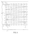
- a lower number of magnetic pads is provided compared to the numbers of pads provided in the configuration of FIG. 5.
- four poles are magnetically coupled instead of two in FIG. 5. The principle of different lengths of the poles remains the same in this configuration.
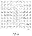
- FIG. 6 provides a variant which solves this problem.
- an elementary head E12n for example, is common to two neighboring columns.
- each air gap is located on a diagonal connecting two magnetic studs, above a - and a single - crossing of excitation wires of the rows and columns.
- the fact that it is not at the center of this pattern does not modify the magnetic excitation which it receives, if the permeability of the material constituting the poles is sufficiently high.
Landscapes
- Engineering & Computer Science (AREA)
- Manufacturing & Machinery (AREA)
- Magnetic Heads (AREA)
- Recording Or Reproducing By Magnetic Means (AREA)
Applications Claiming Priority (2)
| Application Number | Priority Date | Filing Date | Title |
|---|---|---|---|
| FR9506651A FR2735269B1 (fr) | 1995-06-06 | 1995-06-06 | Tete d'enregistrement/lecture matricielle a structure zigzag |
| FR9506651 | 1995-06-06 |
Publications (2)
| Publication Number | Publication Date |
|---|---|
| EP0747889A1 true EP0747889A1 (de) | 1996-12-11 |
| EP0747889B1 EP0747889B1 (de) | 2001-06-20 |
Family
ID=9479666
Family Applications (1)
| Application Number | Title | Priority Date | Filing Date |
|---|---|---|---|
| EP96401139A Expired - Lifetime EP0747889B1 (de) | 1995-06-06 | 1996-05-28 | Matrix-Schreib-/Lesekopf mit Zickzackstruktur |
Country Status (6)
| Country | Link |
|---|---|
| US (1) | US5920448A (de) |
| EP (1) | EP0747889B1 (de) |
| JP (1) | JPH08339506A (de) |
| KR (1) | KR970002884A (de) |
| DE (1) | DE69613431T2 (de) |
| FR (1) | FR2735269B1 (de) |
Families Citing this family (2)
| Publication number | Priority date | Publication date | Assignee | Title |
|---|---|---|---|---|
| EP1196914B1 (de) | 1999-07-09 | 2003-04-09 | Thales | Spurfolgesystem zur aufzeichnung/wiedergabe eines informationsträgers und aufzeichnungsträger |
| EP1498877A1 (de) * | 2003-07-15 | 2005-01-19 | O-Mass AS | Schreibkopfanordnung |
Citations (7)
| Publication number | Priority date | Publication date | Assignee | Title |
|---|---|---|---|---|
| DE1906358A1 (de) * | 1968-02-13 | 1969-08-21 | Ibm | Anordnung und Verfahren zur Herstellung einer Anordnung zur Ein/Aus-Schaltung von Signal-Gebern/Empfaengern,die durch eine Waehlschaltung mit der Signal-Induktionswicklung eines Magnetkopfes verbunden sind |
| NL7107030A (de) * | 1970-05-21 | 1971-11-23 | ||
| US4439793A (en) * | 1981-10-22 | 1984-03-27 | Fuji Photo Film Co., Ltd. | Thin film head array |
| EP0392906A1 (de) * | 1989-04-14 | 1990-10-17 | Thomson-Csf | Statischer Lese-Magnetkopf |
| EP0409675A1 (de) * | 1989-07-21 | 1991-01-23 | Thomson-Csf | Mehrspur-Magnetkopf mit grossem Feldkontrast |
| US5124869A (en) * | 1988-04-27 | 1992-06-23 | Thomson-Csf | Matrix device with magnetic heads, notably in thin layers |
| US5212680A (en) * | 1991-10-10 | 1993-05-18 | International Business Machines Corporation | Mass storage device employing array of transducers "cocked" in relation to reciprocal movement axis |
Family Cites Families (11)
| Publication number | Priority date | Publication date | Assignee | Title |
|---|---|---|---|---|
| JPS54114220A (en) * | 1978-02-27 | 1979-09-06 | Olympus Optical Co Ltd | Magnetic head for plural channels |
| EP0030191B1 (de) * | 1979-12-04 | 1983-05-25 | Thomson-Brandt | Betriebs-Gleichspannungsgenerator und Fernsehempfänger mit einem solchen Generator |
| FR2473238A1 (fr) * | 1980-01-08 | 1981-07-10 | Thomson Brandt | Circuit de commande pour circuit en mode commute, et notamment pour circuit de balayage trame d'un recepteur videofrequence |
| DE3273539D1 (en) * | 1981-06-08 | 1986-11-06 | Hitachi Ltd | Azimuthal magnetic recording and reproducing apparatus |
| FR2545307B1 (fr) * | 1983-04-26 | 1986-03-21 | Thomson Brandt | Appareil de projection d'images videos en couleurs sur un ecran de grandes dimensions |
| FR2579051B1 (fr) * | 1985-03-15 | 1988-06-24 | Loire Electronique | Dispositif de reglage de convergence pour videoprojecteur |
| FR2639137B1 (fr) * | 1988-11-15 | 1990-12-21 | Thomson Csf | Tete magnetique a entrefer saturable et dispositif matriciel comportant un ensemble de telles tetes |
| FR2648608B1 (fr) * | 1989-06-16 | 1991-08-30 | Thomson Csf | Tete magnetique d'enregistrement multipiste a structure matricielle compacte |
| FR2652670B1 (fr) * | 1989-10-03 | 1995-06-23 | Thomson Csf | Tete de lecture magnetooptique a haute resolution. |
| FR2665010B1 (fr) * | 1990-07-20 | 1992-09-18 | Thomson Csf | Dispositif magnetique de lecture a reseau matriciel de tetes de lecture. |
| FR2683063B1 (fr) * | 1991-10-29 | 1998-02-06 | Thomson Csf | Procede de lecture d'informations enregistrees et systeme de lecture. |
-
1995
- 1995-06-06 FR FR9506651A patent/FR2735269B1/fr not_active Expired - Fee Related
-
1996
- 1996-05-28 EP EP96401139A patent/EP0747889B1/de not_active Expired - Lifetime
- 1996-05-28 DE DE69613431T patent/DE69613431T2/de not_active Expired - Lifetime
- 1996-06-03 JP JP8140253A patent/JPH08339506A/ja active Pending
- 1996-06-05 KR KR1019960019902A patent/KR970002884A/ko not_active Ceased
-
1997
- 1997-10-14 US US08/949,398 patent/US5920448A/en not_active Expired - Lifetime
Patent Citations (7)
| Publication number | Priority date | Publication date | Assignee | Title |
|---|---|---|---|---|
| DE1906358A1 (de) * | 1968-02-13 | 1969-08-21 | Ibm | Anordnung und Verfahren zur Herstellung einer Anordnung zur Ein/Aus-Schaltung von Signal-Gebern/Empfaengern,die durch eine Waehlschaltung mit der Signal-Induktionswicklung eines Magnetkopfes verbunden sind |
| NL7107030A (de) * | 1970-05-21 | 1971-11-23 | ||
| US4439793A (en) * | 1981-10-22 | 1984-03-27 | Fuji Photo Film Co., Ltd. | Thin film head array |
| US5124869A (en) * | 1988-04-27 | 1992-06-23 | Thomson-Csf | Matrix device with magnetic heads, notably in thin layers |
| EP0392906A1 (de) * | 1989-04-14 | 1990-10-17 | Thomson-Csf | Statischer Lese-Magnetkopf |
| EP0409675A1 (de) * | 1989-07-21 | 1991-01-23 | Thomson-Csf | Mehrspur-Magnetkopf mit grossem Feldkontrast |
| US5212680A (en) * | 1991-10-10 | 1993-05-18 | International Business Machines Corporation | Mass storage device employing array of transducers "cocked" in relation to reciprocal movement axis |
Non-Patent Citations (1)
| Title |
|---|
| "COMPACT HORIZONTAL HEAD STRUCTURE FOR ARRAYS", IBM TECHNICAL DISCLOSURE BULLETIN, vol. 36, no. 5, 1 May 1993 (1993-05-01), pages 377/378, XP000409027 * |
Also Published As
| Publication number | Publication date |
|---|---|
| FR2735269A1 (fr) | 1996-12-13 |
| DE69613431D1 (de) | 2001-07-26 |
| DE69613431T2 (de) | 2002-06-06 |
| FR2735269B1 (fr) | 1997-07-25 |
| KR970002884A (ko) | 1997-01-28 |
| JPH08339506A (ja) | 1996-12-24 |
| EP0747889B1 (de) | 2001-06-20 |
| US5920448A (en) | 1999-07-06 |
Similar Documents
| Publication | Publication Date | Title |
|---|---|---|
| US4439793A (en) | Thin film head array | |
| EP0694912B1 (de) | Magnetkreise für Aufzeichnungs-/Wiedergabemagnetkopfanordnung | |
| CN101127214B (zh) | 磁头、磁带驱动系统和磁记录带 | |
| KR940012244A (ko) | 2중 소자 자기저항 감지헤드와 그 감지헤드를 갖춘 판독/기록 자기헤드 | |
| CN101256780A (zh) | 图案化磁记录介质及具有该介质的磁记录系统 | |
| KR950030051A (ko) | 열 노이즈 제거 수단을 갖춘 자기 저항(mr) 판독 변환기와 그 변환기를 포함하는 디스크 드라이브 | |
| KR101255051B1 (ko) | 수퍼 트랙을 가지는 비트 패턴 매체, 재생 헤드 및 수퍼트랙을 가지는 비트패턴 매체에 정보를 기록 재생하는 하드디스크 드라이브 | |
| US20070030594A1 (en) | Tape recording head with overlapping read transducers | |
| JP2000090491A5 (de) | ||
| FR2519175A1 (fr) | Unite de tete rotative | |
| EP0747889B1 (de) | Matrix-Schreib-/Lesekopf mit Zickzackstruktur | |
| EP0409675B1 (de) | Mehrspur-Magnetkopf mit grossem Feldkontrast | |
| KR20020018585A (ko) | 헤드 조립체의 제조방법 및 헤드 조립체 | |
| US20050013042A1 (en) | Write head layout | |
| FR2656454A1 (fr) | Tete de lecture multipiste. | |
| EP0652549B1 (de) | Magnetischer Aufnahme-/Wiedergabekopf | |
| JP4151623B2 (ja) | 磁気ヘッド装置および磁気記録装置 | |
| JPS62295233A (ja) | 光デイスクのテストデイスク | |
| JPH0443338B2 (de) | ||
| JP2956796B2 (ja) | 磁気ディスク装置 | |
| JPS58203620A (ja) | デ−タ面サ−ボ方式 | |
| JP3361345B2 (ja) | 磁気記録装置 | |
| JPH01217718A (ja) | 薄膜マルチ磁気ヘッド | |
| JP2501270B2 (ja) | 光学的情報記録方法 | |
| JP2000339638A (ja) | 薄膜磁気ヘッドとそのスライダ及び磁気記録再生装置 |
Legal Events
| Date | Code | Title | Description |
|---|---|---|---|
| PUAI | Public reference made under article 153(3) epc to a published international application that has entered the european phase |
Free format text: ORIGINAL CODE: 0009012 |
|
| AK | Designated contracting states |
Kind code of ref document: A1 Designated state(s): DE GB IT NL |
|
| 17P | Request for examination filed |
Effective date: 19970210 |
|
| GRAG | Despatch of communication of intention to grant |
Free format text: ORIGINAL CODE: EPIDOS AGRA |
|
| GRAG | Despatch of communication of intention to grant |
Free format text: ORIGINAL CODE: EPIDOS AGRA |
|
| GRAG | Despatch of communication of intention to grant |
Free format text: ORIGINAL CODE: EPIDOS AGRA |
|
| 17Q | First examination report despatched |
Effective date: 20000807 |
|
| GRAG | Despatch of communication of intention to grant |
Free format text: ORIGINAL CODE: EPIDOS AGRA |
|
| GRAH | Despatch of communication of intention to grant a patent |
Free format text: ORIGINAL CODE: EPIDOS IGRA |
|
| GRAH | Despatch of communication of intention to grant a patent |
Free format text: ORIGINAL CODE: EPIDOS IGRA |
|
| GRAA | (expected) grant |
Free format text: ORIGINAL CODE: 0009210 |
|
| AK | Designated contracting states |
Kind code of ref document: B1 Designated state(s): DE GB IT NL |
|
| REF | Corresponds to: |
Ref document number: 69613431 Country of ref document: DE Date of ref document: 20010726 |
|
| ITF | It: translation for a ep patent filed | ||
| GBT | Gb: translation of ep patent filed (gb section 77(6)(a)/1977) |
Effective date: 20010907 |
|
| RAP2 | Party data changed (patent owner data changed or rights of a patent transferred) |
Owner name: THALES |
|
| NLT2 | Nl: modifications (of names), taken from the european patent patent bulletin |
Owner name: THALES |
|
| REG | Reference to a national code |
Ref country code: GB Ref legal event code: IF02 |
|
| PLBE | No opposition filed within time limit |
Free format text: ORIGINAL CODE: 0009261 |
|
| STAA | Information on the status of an ep patent application or granted ep patent |
Free format text: STATUS: NO OPPOSITION FILED WITHIN TIME LIMIT |
|
| 26N | No opposition filed | ||
| PGFP | Annual fee paid to national office [announced via postgrant information from national office to epo] |
Ref country code: NL Payment date: 20040505 Year of fee payment: 9 |
|
| PG25 | Lapsed in a contracting state [announced via postgrant information from national office to epo] |
Ref country code: NL Free format text: LAPSE BECAUSE OF NON-PAYMENT OF DUE FEES Effective date: 20051201 |
|
| NLV4 | Nl: lapsed or anulled due to non-payment of the annual fee |
Effective date: 20051201 |
|
| PGFP | Annual fee paid to national office [announced via postgrant information from national office to epo] |
Ref country code: IT Payment date: 20090520 Year of fee payment: 14 |
|
| REG | Reference to a national code |
Ref country code: GB Ref legal event code: 732E Free format text: REGISTERED BETWEEN 20100408 AND 20100414 |
|
| PG25 | Lapsed in a contracting state [announced via postgrant information from national office to epo] |
Ref country code: IT Free format text: LAPSE BECAUSE OF NON-PAYMENT OF DUE FEES Effective date: 20100528 |
|
| PGFP | Annual fee paid to national office [announced via postgrant information from national office to epo] |
Ref country code: DE Payment date: 20120531 Year of fee payment: 17 |
|
| PGFP | Annual fee paid to national office [announced via postgrant information from national office to epo] |
Ref country code: GB Payment date: 20120426 Year of fee payment: 17 |
|
| GBPC | Gb: european patent ceased through non-payment of renewal fee |
Effective date: 20130528 |
|
| PG25 | Lapsed in a contracting state [announced via postgrant information from national office to epo] |
Ref country code: DE Free format text: LAPSE BECAUSE OF NON-PAYMENT OF DUE FEES Effective date: 20131203 |
|
| REG | Reference to a national code |
Ref country code: DE Ref legal event code: R119 Ref document number: 69613431 Country of ref document: DE Effective date: 20131203 |
|
| PG25 | Lapsed in a contracting state [announced via postgrant information from national office to epo] |
Ref country code: GB Free format text: LAPSE BECAUSE OF NON-PAYMENT OF DUE FEES Effective date: 20130528 |