EP0748010B1 - Laser-System - Google Patents
Laser-System Download PDFInfo
- Publication number
- EP0748010B1 EP0748010B1 EP96304078A EP96304078A EP0748010B1 EP 0748010 B1 EP0748010 B1 EP 0748010B1 EP 96304078 A EP96304078 A EP 96304078A EP 96304078 A EP96304078 A EP 96304078A EP 0748010 B1 EP0748010 B1 EP 0748010B1
- Authority
- EP
- European Patent Office
- Prior art keywords
- output
- output coupler
- laser
- input face
- resonator
- Prior art date
- Legal status (The legal status is an assumption and is not a legal conclusion. Google has not performed a legal analysis and makes no representation as to the accuracy of the status listed.)
- Expired - Lifetime
Links
Images

Classifications
-
- H—ELECTRICITY
- H01—ELECTRIC ELEMENTS
- H01S—DEVICES USING THE PROCESS OF LIGHT AMPLIFICATION BY STIMULATED EMISSION OF RADIATION [LASER] TO AMPLIFY OR GENERATE LIGHT; DEVICES USING STIMULATED EMISSION OF ELECTROMAGNETIC RADIATION IN WAVE RANGES OTHER THAN OPTICAL
- H01S3/00—Lasers, i.e. devices using stimulated emission of electromagnetic radiation in the infrared, visible or ultraviolet wave range
- H01S3/23—Arrangements of two or more lasers not provided for in groups H01S3/02 - H01S3/22, e.g. tandem arrangements of separate active media
- H01S3/2308—Amplifier arrangements, e.g. MOPA
Definitions
- This invention relates to a laser system.
- it relates to a solid state laser system in which at least two active laser elements are provided in a single pumping section, for example in an oscillator-amplifier configuration.
- solid state laser systems generally comprise a resonator bounded by one totally reflecting mirror and one partially transmitting mirror and a solid state active laser element between the two mirrors.
- the laser element may typically be of Nd:YAG but may be of other substances.
- the laser element is excited in a pumping section, typically by optical pumping lamps and the laser light is output through the partially transmissive mirror.
- the laser element therefore acts as an oscillator. It is also well known to improve the performance of such systems by using a further solid state active laser element in the output path as an amplifier.
- FIG. 1 In order to visualise the axial and transverse distribution of circulating laser power within a laser resonator, it is usual to depict this by overlaying the limits of the highest order mode of the resonator on a scale drawing of the resonator. These limits then define the 'mode envelope' and 'mode shape' of the distribution.
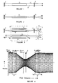
- An ideal low power oscillator would have the distribution shown schematically in Figure 1.
- reference numerals 1 and 3 refer respectively to a plane partially-transmitting output coupler and a plane totally-reflecting rear mirror.
- a solid state active gain laser element 2 is positioned between the two mirrors.
- the mode envelope is designated by 2'.
- the laser intensity within the resonator is generally highest along the central axis thereof and decreases with increasing radius.
- the mode envelope represents the locus of points where the circulating intensity is 1/e 2 times the corresponding peak (ie axial) circulating intensity, or within which a certain percentage (usually 86% or 90%) of the circulating power is contained.
- the mode diameter at any point within the resonator defined as the width of the mode envelope at that point, will generally be governed by the components, the spacing of the optical components within, and bounding, the resonator and the optical powers of these components.
- Figure 1 shows the situation where the laser element 2 has no optical power and the mirrors are both plane mirrors and therefore the diameter of beam B is essentially constant.
- the mode diameter varies within the resonator. It is well known that when a solid state laser element, and in particular a cylindrical element, is excited above fairly modest input power levels, the element develops optical power which is usually positive optical power. This occurs because of relatively poor thermal conductivity of the element, leading to the build up of a temperature gradient between the axis and wall of the element. This effect is known is as "thermal lensing". The lensing effect is distributed over the element in its axial direction. Thus, for simplicity it can be envisaged as arising from a convex lens situated at an effective plane, mid-way along the element. This effect is illustrated in EP-A-0 400 830.
- a laser element when a laser element exhibits thermal lensing, it behaves as an optical duct with a quadratic transverse variation of refractive index.
- the relationship between input and output beams for the element may be calculated using ABCD optical matrices or ray-tracing techniques.
- Figure 2 shows schematically an oscillator operated at higher power in which the solid state laser element 2 develops thermal lensing.
- the beam is widest at element 2 and narrows towards the two mirrors 1 and 3. Since mirror 1 is a plane mirror, the mode envelope exhibits a beam waist at mirror 1, resulting in a divergent output beam from the output coupler mirror 1.
- the output beam divergence is inversely proportional to the mode diameter of the waist at the output coupler. Since the diameter of the beam waist at mirror 1 varies with the separation of the mirror from laser element 2 it will be appreciated that if the output coupler is situated farther away from the solid state laser element then the beam waist diameter at the output coupler will be quite small and therefore the divergence will be large. This is generally unsatisfactory for practical applications and requires correction.
- Correction is necessary because laser users typically require a collimated output beam since its characteristics, particularly beam diameter, do not vary significantly with propagation distance. This correction can be achieved by using lenses but since the effect varies with pumping power it is difficult to correct properly over a range of pumping powers.
- Each amplifier in such a chain receives an input beam from a preceding amplifier or from the oscillator and has its own respective optical pumping section containing the amplifying laser element, excitation lamp or lamps and other components.
- US patents US-A-4,860,301 disclose and US-A-4,858,239 laser systems in which an oscillator element and one or more amplifying elements are all mounted in a common optical pumping section, sharing excitation (pumping) lamps and power supplies and are configured such that the oscillator element is in a resonator and the light emerging from the resonator is reflected back towards the or each respective amplifying element.
- the present invention relates to systems of this type, as shown schematically in Figure 3. As shown in the figure, the system involves a single pumping section 4 incorporating two laser elements 2 and 5 configured, respectively, as oscillator and amplifier elements. Oscillator element 2 is mounted between mirrors 1 and 3 to form an oscillator as in Figures 1 and 2 and the output beam from the oscillator is directed back towards the amplifier element 5 by a beam turning system 6.
- Pumping sections for solid state lasers are generally fairly inefficient at transferring excitation energy, from excitational pumping lamps for example, to the solid state laser element.
- the proportion of the excitation light which is captured by the solid state element is primarily related to the ratio of the total cross sectional area of the laser element to that enclosed within the pumping section.
- the excitation efficiency is also reduced due to fixed loss mechanisms for the excitation radiation at the ends of the pumping section. This is because the materials forming the ends of the enclosure generally have lower reflectivity and also are provided with spaces or annuli for the delivery of cooling fluid to the laser element and excitation lamps.
- the effect of placing more than one laser element inside a pumping section is to increase the proportion of light emitted by the excitation lamp or lamps that is intersected by the combined laser elements and therefore to improve laser output power. It has indeed been found that placing two solid state laser elements within a single pumping section can increase system efficiency by up to 80%.
- a laser system comprising: first and second solid state active gain elements, the second element having an input face and output face; common optical pumping means for exciting said elements, the excitation being such as to induce thermal lensing power at least in the second element; a laser resonator comprising at least an output coupler, wherein the first element is located within the resonator and provides a beam to be emitted from the output coupler; optical coupling means for coupling and steering the output beam from the output coupler into the input face of the second element, wherein the output beam from the output coupler is a divergent beam having a wavefront with a radius of curvature that increases with propagation distance from the output coupler in the region of the second element; the system being configured such that the wavefront radius of curvature at the input face of the second element is matched to the thermal lensing power of the second element so that a substantially collimated beam emerges from the output face of the second element.
- a method for obtaining a substantially collimated output beam from a laser system comprising first and second solid state active gain elements, the second element having an input face and output face; common optical pumping means for exciting said elements, the excitation being such as to induce thermal lensing power at least in the second element; a laser resonator comprising at least an output coupler, the first element being located within the resonator and providing an output beam from the output coupler; and optical coupling means for coupling and steering the output beam from the output coupler into the input face of the second element, the method comprising obtaining an output beam from the output coupler which is divergent, having a wavefront with a radius of curvature that increases with propagation distance in the region of the second element, wherein the radius of curvature of the beam waveform at the input face of the second element is selected or adjusted so that it matches the thermal lensing power of the second element so as to obtain a substantially collimated output beam from the second element.
- the radius of curvature will not generally be actually measured, although it can be calculated, instead the configuration of the components may be adjusted until collimation is achieved.
- a laser system embodying the present invention comprises a common pumping section 4 having one or more excitation lamps 7 for providing excitation radiation to two solid state active laser elements 2 and 5.
- Element 2 is configured as an oscillator in a resonator bounded by a reflecting mirror 3 and a partially transmissive output coupler 1. Although these are shown as plane in the figure, one or more of them may be curved.
- Excitation radiation from the lamp 7 excites laser element 2 in the normal manner and an output beam is produced at output coupler 1.
- This is applied to a beam turning system 6 which is shown in the figure as comprising two plane mirrors 8 and 9.
- other bending systems may be used such as a plurality of prisms, a single multi-faced prism, curved elements, etc.
- Figure 6 shows schematically a prism 6a forming an alternative beam turning mechanism.
- Beam turning apparatus 6 turns the output beam through 180° to the second solid state laser active gain element 5.
- Element 5 is also acted upon by excitation from lamp or lamps 7 and serves as an amplifier element to produce a laser output beam 10. This beam provides the output beam for materials processing or any other laser application.
- the laser elements are Nd:YAG elements but they may be any other types of solid state laser elements.
- the laser may be operated in any mode of operation ranging from continuous operation to pulsed operation at any desired duty cycle.
- the oscillator element 2 develops thermal lensing and therefore the beam from coupler 1 is divergent, having a wavefront radius of curvature which increases as the distance from coupler 1 increases, at least in the region of second element 5.
- Beam turner 6 is configured such that it does not itself have any optical power and merely turns the beam without altering its divergence.
- the divergence of the beam entering the input face 5a of the amplifier element 5 may be controlled by, inter alia, altering the spacing between coupler 1 and element 2.
- element 5 also develops thermal lensing and therefore, by adjusting the apparatus so that the divergence of the beam impinging upon input face 5a is sufficient to compensate for the thermal lensing effect of element 5, then the beam emerging from the output face 5b of element 5 will generally be collimated.
- Figure 4 illustrates the mode shape for one embodiment of the invention. It should be noted that in this diagram a linear beam path has been shown as if the beam continues in a straight line since the beam turning means 6 has no effect on the mode shape itself.
- the output coupler is placed farther from the oscillator element 2 than the rear mirror 3.
- the mirrors may be of different curvature.
- An example is shown in Figure 4 in which the output coupler is convex while the rear mirror is plane.
- Figure 5 shows the output coupler 1 is an equi-thickness convex mirror, with the convex faces directed toward the oscillator rod 2.
- the embodiment of Figure 4 results in a beam waist between the output coupler 1 and the beam turner 6.
- the output coupler is convex, with radius of curvature 330 mm, and the resonator length is about 400-600 mm.
- the effect of a system as shown in Figure 4 is that the mode diameter at output coupler 1 is significantly smaller than at mirror 3 and therefore the output beam divergence is large.
- the mode diameter generally reduces towards coupler 1 and is divergent in the region between a beam waist, located after the coupler, and the amplifier 5.
- the thermal lensing effect of amplifier 5 tends to converge the input beam and therefore, if the converging thermal lensing effect of element 5 is approximately matched to the radius of curvature of the beam wavefront at the input face 5a of element 5 then the output beam from output face 5b of element 5 will be approximately collimated.
- thermal powers of elements 2 and 5 are fixed, then compensation can be achieved by altering the relative spacing of, inter alia, element 2, output coupler 1 and element 5.
- the position of output coupler 1 may be varied, to alter the wavefront curvature at input face 5d.
- output coupler 1 may have optical power (eg be a curved mirror) and the degree of curvature chosen appropriately.
- Beam turner 6 may also or alternatively have optical power and be shifted to increase or decrease the wavefront curvature at input face 5a.
- Other types of adjustment suitable to substantially compensate the effect of the beam divergence at the input face 5a of element 5 with the thermal lensing power of element 5 will be apparent.
- variables affecting collimation are the curvature (if any) of the coupling mirrors, the thermal lensing power of the laser elements, and the spacing between the output coupler and the amplifier element. Any of these, or other variables, may be adjusted, whether singly or in combination.
- more than one amplifier element may be used, each additional amplifier being incorporated in the same single pumping section as the other laser elements.
- the output beam from one amplifier element is turned back as an input to another amplifier element, in which case the combined optical powers of the amplifier elements are used to correct the collimation of a final output beam.
- the beam turner 6 is located approximately at or close to the beam waist of the oscillator output beam. This is desired, but not essential, since it leads to optimum extraction of stored energy from both laser elements, as follows. If the beam waist is located approximately mid-way between oscillator element 2 and amplifier laser elements 5 then, because the mode shape is symmetrical about the position of the beam waist, the respective mode diameters at elements 2 and 5 will be similar. Since in the embodiment shown elements 2 and 5 have the same diameter, this means that the ratio of mode diameter to element diameter is similar for each element. This ratio can therefore be optimised for maximum output power.
Landscapes
- Physics & Mathematics (AREA)
- Electromagnetism (AREA)
- Engineering & Computer Science (AREA)
- Plasma & Fusion (AREA)
- Optics & Photonics (AREA)
- Lasers (AREA)
Claims (10)
- Lasersystem mit ersten und zweiten aktiven Verstärkerelementen auf Festkörperbasis (2, 5), wobei das zweite Element eine Eingangsfläche (5a) und eine Ausgangsfläche (5b) aufweist, mit gemeinsamen optischen Pumpmitteln (4) zur Anregung der Elemente, wobei die Anregung derart eingerichtet ist, das eine thermische linsenbildende Leistung wenigstens in dem zweiten Element induziert wird, mit einem wenigstens einen Ausgangskoppler (1) aufweisenden Laserresonator (1, 3, 4), wobei das erste Element innerhalb des Resonators angeordnet ist und einen von dem Ausgangskoppler zu emitierenden Strahl liefert, mit einem optischen Koppelmittel (6) zur Vermittlung und Ausrichtung des Ausgangsstrahls von dem Ausgangskoppler auf die Eingangsfläche des zweiten Elementes, wobei der Ausgangsstrahl des Ausgangskopplers ein divergenter Strahl ist, der eine Wellenfront mit einem Krümmungsradius aufweist, der in Ausbreitungsrichtung in den Bereich des zweiten Elementes mit dem Abstand von dem Ausgangskoppler zunimmt, wobei das System so eingerichtet ist, dass der Krümmungsradius der Wellenfront an der Eingangsfläche des zweiten Elementes an die thermische linsenbildende Leistung des zweiten Elementes angepaßt ist, so dass von der Ausgangsfläche des zweiten Elementes ein im wesentlichen kollimierter Strahl (10) ausgeht.
- Lasersystem nach Anspruch 1, bei dem das zweite Element ein Verstärker (5) ist.
- Lasersystem nach Anspruch 1 oder Anspruch 2, bei dem die Relativposition des Ausgangskopplers variabel ist, um den Krümmungsradius der Wellenfront an der Eingangsfläche des zweiten Elementes zu verändern.
- Lasersystem nach einem der vorangehenden Ansprüche, bei dem der Resonator wenigstens ein gekrümmtes optisches Bauteil (1) umfaßt.
- Lasersystem nach einem der vorangehenden Ansprüche, bei dem der Resonator zwei Spiegel (1, 3) umfaßt, wobei der Spiegel (1), bei dem der Modendurchmesser am geringsten ist, als der Ausgangskoppler verwendet wird.
- Laserssystem nach einem der vorangehenden Ansprüche, bei dem das optische Koppelmittel so angeordnet ist, dass das Verhältnis von Modendurchmesser zu Elementdurchmesser an der Eingangsfläche des zweiten Elementes und der benachbarten Fläche des ersten Elementes gleich ist.
- Laserssystem nach Anspruch 6, bei dem das optische Koppelmittel ein Prisma (6a) ist.
- Verfahren zur Erzeugung eines im wesentlichen kollimierten Ausgangsstrahls aus einem Lasersystem mit ersten und zweiten aktiven Verstärkerelementen auf Festkörperbasis (2, 5), wobei das zweite Element eine Eingangsfläche (5a) und eine Ausgangsfläche (5b) aufweist, mit gemeinsamen optischen Pumpmitteln (4) zur Anregung in der Elemente, wobei die Anregung derart eingerichtet ist, das eine thermische linsenbildende Leistung wenigstens in dem zweiten Element induziert wird, mit einem wenigstens einen Ausgangskoppler aufweisenden Laserresonator (1, 3, 4), wobei das erste Element innerhalb des Resonators angeordnet ist und von dem Ausgangskoppler einen Strahl liefert, und mit einem optischen Koppelmittel (6) zur Vermittlung und Ausrichtung des Ausgangsstrahls von dem Ausgangskoppler auf die Eingangsfläche des zweiten Elementes, wobei bei dem Verfahren von dem Ausgangskoppler ein Ausgangsstrahl bereitgestellt wird, der divergent ist und eine Wellenfront mit einem Krümmungsradius aufweist, der in Ausbreitungsrichtung in den Bereich des zweiten Elementes mit dem Abstand von dem Ausgangskoppler zunimmt, wobei der Krümmungsradius des Strahls an der Eingangsfläche des zweiten Elementes so ausgewählt oder eingerichtet ist, dass er an die thermische linsenbildende Leistung des zweiten Elementes angepaßt ist, um von dem zweiten Element einen im wesentlichen kollimierten Ausgangsstrahl (10) zu erhalten.
- Verfahren nach Anspruch 8, bei dem die Kollimierung durch Auswahl eines Parameters oder mehrerer Parameter aus der folgenden Gruppe von Parametern erfolgt: der optischen Weglänge zwischen dem Ausgangskoppler und der Eingangsfläche des zweiten Elementes, der Krümmung von einem oder mehreren optischen Elementen in dem System und der thermischen linsenbildenden Leistung von einem Verstärkerelement oder mehreren Verstärkerelementen.
- Verfahren nach Anspruch 8 oder Anspruch 9, bei dem die Auswahl oder Einrichtung bei einem vorbestimmten Anregungspegel ausgeführt wird.
Applications Claiming Priority (2)
| Application Number | Priority Date | Filing Date | Title |
|---|---|---|---|
| GB9511688 | 1995-06-09 | ||
| GBGB9511688.5A GB9511688D0 (en) | 1995-06-09 | 1995-06-09 | Laser system |
Publications (2)
| Publication Number | Publication Date |
|---|---|
| EP0748010A1 EP0748010A1 (de) | 1996-12-11 |
| EP0748010B1 true EP0748010B1 (de) | 2000-08-09 |
Family
ID=10775774
Family Applications (1)
| Application Number | Title | Priority Date | Filing Date |
|---|---|---|---|
| EP96304078A Expired - Lifetime EP0748010B1 (de) | 1995-06-09 | 1996-06-04 | Laser-System |
Country Status (4)
| Country | Link |
|---|---|
| US (1) | US5699376A (de) |
| EP (1) | EP0748010B1 (de) |
| DE (1) | DE69609672T2 (de) |
| GB (1) | GB9511688D0 (de) |
Families Citing this family (7)
| Publication number | Priority date | Publication date | Assignee | Title |
|---|---|---|---|---|
| JP3644145B2 (ja) * | 1996-08-21 | 2005-04-27 | 三菱電機株式会社 | レーザ装置 |
| US5912912A (en) * | 1997-09-05 | 1999-06-15 | Coherent, Inc. | Repetitively-pulsed solid-state laser having resonator including multiple different gain-media |
| EP0992090B1 (de) * | 1998-04-22 | 2003-11-19 | Carl Baasel Lasertechnik GmbH | Resonatoranordnung für festkörperlaser |
| DE10043269C2 (de) * | 2000-08-29 | 2002-10-24 | Jenoptik Jena Gmbh | Diodengepumpter Laserverstärker |
| JP2007523499A (ja) * | 2004-02-23 | 2007-08-16 | パワーレイズ・リミテッド | レーザ装置 |
| KR101371199B1 (ko) * | 2012-04-26 | 2014-03-10 | 원텍 주식회사 | 더블펄스 레이저 발생장치 및 더블펄스 레이저 발생방법 |
| US10511145B2 (en) * | 2016-12-21 | 2019-12-17 | Arizona Board of Regents on behalf of the University of Arizon | Generation of high-power spatially-restructurable spectrally-tunable beams in a multi-arm-cavity VECSEL-based laser system |
Family Cites Families (10)
| Publication number | Priority date | Publication date | Assignee | Title |
|---|---|---|---|---|
| US4860301A (en) * | 1984-06-14 | 1989-08-22 | Peter Nicholson | Multiple crystal pumping cavity laser with thermal and mechanical isolation |
| US4713820A (en) * | 1985-08-02 | 1987-12-15 | Allied Corporation | Thermal lensing-compensated lanthanum beryllate laser |
| US4803694A (en) * | 1987-07-08 | 1989-02-07 | Amada Company, Limited | Laser resonator |
| US4858239A (en) * | 1988-05-26 | 1989-08-15 | Elop Electrooptics Industries Ltd. | Laser system |
| GB8912765D0 (en) * | 1989-06-02 | 1989-07-19 | Lumonics Ltd | A laser |
| US5046070A (en) * | 1990-05-22 | 1991-09-03 | Coherent, Inc. | Longitudinally laser pumped laser with compensation for thermal lens effects |
| US5170406A (en) * | 1991-03-13 | 1992-12-08 | Amoco Corporation | High-power, end-pumped solid state laser |
| US5548608A (en) * | 1993-02-08 | 1996-08-20 | Zhang; Tong | Laser head and telescopic cavity for diode-pumped solid-state lasers |
| US5528612A (en) * | 1993-11-19 | 1996-06-18 | The United States Of America As Represented By The Secretary Of The Navy | Laser with multiple gain elements |
| US5410559A (en) * | 1994-02-04 | 1995-04-25 | Spectra-Physics Lasers, Inc. | Diode pumped laser with strong thermal lens crystal |
-
1995
- 1995-06-09 GB GBGB9511688.5A patent/GB9511688D0/en active Pending
-
1996
- 1996-06-04 EP EP96304078A patent/EP0748010B1/de not_active Expired - Lifetime
- 1996-06-04 DE DE69609672T patent/DE69609672T2/de not_active Expired - Fee Related
- 1996-06-07 US US08/659,892 patent/US5699376A/en not_active Expired - Fee Related
Also Published As
| Publication number | Publication date |
|---|---|
| US5699376A (en) | 1997-12-16 |
| DE69609672T2 (de) | 2000-12-07 |
| EP0748010A1 (de) | 1996-12-11 |
| GB9511688D0 (en) | 1995-08-02 |
| DE69609672D1 (de) | 2000-09-14 |
Similar Documents
| Publication | Publication Date | Title |
|---|---|---|
| US4656641A (en) | Laser cavity optical system for stabilizing the beam from a phase locked multi-emitter broad emitter laser | |
| US10418774B2 (en) | Spectrally multiplexing diode pump modules to improve brightness | |
| JP3589299B2 (ja) | ビーム整形装置 | |
| US4916712A (en) | Optically pumped slab laser | |
| JPH03214682A (ja) | レーザ | |
| EP3097613B1 (de) | Laser und verstärker auf grundlage von fasern mit mehreren pumppassagen | |
| US5048044A (en) | Optically pumped lasers | |
| US20070068475A1 (en) | Internal combustion engine with a laser light generating device | |
| CA2329089C (en) | Fiber grating feedback stabilization of broad area laser diode | |
| IL257272A (en) | High power self-seeding laser power | |
| US5699376A (en) | Laser system and method using plural gain elements and thermal lensing | |
| JP2001077449A (ja) | モード同期固体レーザ | |
| US5757842A (en) | Method and apparatus for compensating thermal lensing effects in a laser cavity | |
| EP0979546A1 (de) | Optische resonatoren mit diskontinuierlichen phasenbauelementen | |
| US3825856A (en) | Laser generator for single transverse mode operation | |
| US5325390A (en) | Correction of thermally-induced aberration in end-pumped solid-state lasers | |
| US5943358A (en) | Non-confocal unstable laser resonator and outcoupler | |
| US5513205A (en) | End-pumping laser configuration utilizing a retroreflector as an input coupler | |
| US5907574A (en) | High power infrared laser system | |
| US6553054B1 (en) | Laser resonator having improved efficiency and beam uniformity and associated method | |
| KR100257401B1 (ko) | 출력조절식 레이저 광 발생장치 | |
| JP2000340868A (ja) | 固体レーザ装置及びこれを用いたレーザ加工装置 | |
| RU2029422C1 (ru) | Неустойчивый многопроходный лазерный резонатор | |
| US4513421A (en) | Peripheral gain suppression in a laser medium | |
| GB2276031A (en) | Solid laser device |
Legal Events
| Date | Code | Title | Description |
|---|---|---|---|
| PUAI | Public reference made under article 153(3) epc to a published international application that has entered the european phase |
Free format text: ORIGINAL CODE: 0009012 |
|
| AK | Designated contracting states |
Kind code of ref document: A1 Designated state(s): DE GB |
|
| 17P | Request for examination filed |
Effective date: 19970512 |
|
| GRAG | Despatch of communication of intention to grant |
Free format text: ORIGINAL CODE: EPIDOS AGRA |
|
| 17Q | First examination report despatched |
Effective date: 19991022 |
|
| GRAG | Despatch of communication of intention to grant |
Free format text: ORIGINAL CODE: EPIDOS AGRA |
|
| GRAH | Despatch of communication of intention to grant a patent |
Free format text: ORIGINAL CODE: EPIDOS IGRA |
|
| GRAH | Despatch of communication of intention to grant a patent |
Free format text: ORIGINAL CODE: EPIDOS IGRA |
|
| GRAA | (expected) grant |
Free format text: ORIGINAL CODE: 0009210 |
|
| AK | Designated contracting states |
Kind code of ref document: B1 Designated state(s): DE GB |
|
| REF | Corresponds to: |
Ref document number: 69609672 Country of ref document: DE Date of ref document: 20000914 |
|
| EN | Fr: translation not filed | ||
| PLBE | No opposition filed within time limit |
Free format text: ORIGINAL CODE: 0009261 |
|
| STAA | Information on the status of an ep patent application or granted ep patent |
Free format text: STATUS: NO OPPOSITION FILED WITHIN TIME LIMIT |
|
| 26N | No opposition filed | ||
| REG | Reference to a national code |
Ref country code: GB Ref legal event code: IF02 |
|
| PGFP | Annual fee paid to national office [announced via postgrant information from national office to epo] |
Ref country code: DE Payment date: 20080731 Year of fee payment: 13 |
|
| PGFP | Annual fee paid to national office [announced via postgrant information from national office to epo] |
Ref country code: GB Payment date: 20080627 Year of fee payment: 13 |
|
| GBPC | Gb: european patent ceased through non-payment of renewal fee |
Effective date: 20090604 |
|
| PG25 | Lapsed in a contracting state [announced via postgrant information from national office to epo] |
Ref country code: GB Free format text: LAPSE BECAUSE OF NON-PAYMENT OF DUE FEES Effective date: 20090604 |
|
| PG25 | Lapsed in a contracting state [announced via postgrant information from national office to epo] |
Ref country code: DE Free format text: LAPSE BECAUSE OF NON-PAYMENT OF DUE FEES Effective date: 20100101 |