EP0748014A1 - Dispositif pour l'agencement des appareils de commutation électriques en étages - Google Patents
Dispositif pour l'agencement des appareils de commutation électriques en étages Download PDFInfo
- Publication number
- EP0748014A1 EP0748014A1 EP96108187A EP96108187A EP0748014A1 EP 0748014 A1 EP0748014 A1 EP 0748014A1 EP 96108187 A EP96108187 A EP 96108187A EP 96108187 A EP96108187 A EP 96108187A EP 0748014 A1 EP0748014 A1 EP 0748014A1
- Authority
- EP
- European Patent Office
- Prior art keywords
- bracket
- plate
- push plate
- switching device
- support plate
- Prior art date
- Legal status (The legal status is an assumption and is not a legal conclusion. Google has not performed a legal analysis and makes no representation as to the accuracy of the status listed.)
- Granted
Links
- 125000006850 spacer group Chemical group 0.000 description 4
- 238000003780 insertion Methods 0.000 description 2
- 230000037431 insertion Effects 0.000 description 2
- 238000004519 manufacturing process Methods 0.000 description 1
- 230000006641 stabilisation Effects 0.000 description 1
- 238000011105 stabilization Methods 0.000 description 1
Images


Classifications
-
- H—ELECTRICITY
- H02—GENERATION; CONVERSION OR DISTRIBUTION OF ELECTRIC POWER
- H02B—BOARDS, SUBSTATIONS OR SWITCHING ARRANGEMENTS FOR THE SUPPLY OR DISTRIBUTION OF ELECTRIC POWER
- H02B1/00—Frameworks, boards, panels, desks, casings; Details of substations or switching arrangements
- H02B1/26—Casings; Parts thereof or accessories therefor
- H02B1/30—Cabinet-type casings; Parts thereof or accessories therefor
- H02B1/32—Mounting of devices therein
-
- H—ELECTRICITY
- H02—GENERATION; CONVERSION OR DISTRIBUTION OF ELECTRIC POWER
- H02B—BOARDS, SUBSTATIONS OR SWITCHING ARRANGEMENTS FOR THE SUPPLY OR DISTRIBUTION OF ELECTRIC POWER
- H02B1/00—Frameworks, boards, panels, desks, casings; Details of substations or switching arrangements
- H02B1/26—Casings; Parts thereof or accessories therefor
- H02B1/40—Wall-mounted casings; Parts thereof or accessories therefor
- H02B1/42—Mounting of devices therein
Definitions
- the invention relates to a device for the tiered arrangement of switching devices.
- a generic device is known from EP 0 352 149 A1.
- two connection blocks are connected to each other via a top-hat rail onto which a switching device can be snapped on.
- these connecting blocks can be coupled to another top-hat rail, which e.g. is attached to a support plate.
- a further switching device can be coupled to a connection block on the outside facing away from the support plate, which is arranged closer to the operator than the rear hat rail on the support plate and is therefore more accessible.
- another switching device is accommodated in an intermediate level.
- the disadvantage of this arrangement is that the space between the support plate and the switching device spaced from it via the connection blocks remains unused.
- the invention has for its object to provide a device of the type mentioned above, which is simple and inexpensive to manufacture, enables easy handling during assembly and disassembly of the switching devices and enables improved use of space.
- leg ends of the bracket are designed as guide rails.
- the front plate of a busbar adapter advantageously serves as a support plate.
- fastening means are provided on the push plate on the side facing the intermediate space.
- latching arms with latching lugs are provided on the pusher plate, which can be latched in shape-matched recesses on the inside of the leg ends of the bracket, simple fixing of the pusher plate in the operating position is achieved in this way.
- the first switching device can be locked on the web of the bracket.
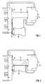
- the U-shaped bracket 2 is attached to the front plate 4 of the busbar adapter 1 and carries a circuit breaker 5 as the first switching device at its end facing away from the front plate 4.
- the push plate 3 is rectangular and lies on the front plate 4.
- a contactor 6 is latched on the push plate 3 as a second switching device.
- the switching devices 5, 6 are not only assembled or disassembled, but also the line connections are made, for example, between the circuit breaker 5 and the busbar adapter 1 and between the circuit breaker 5 and the contactor 6.
- FIG. 2 shows the operating position of the device according to the invention, in which the push plate 3 with the snapped contactor 6 is inserted into the space formed by the bracket 2, so that the two switching devices 5, 6 are arranged one behind the other or in tiers. Otherwise, FIG. 2 agrees with the illustration in FIG. 1, and a further description is therefore unnecessary.
- FIG. 3 shows the front view of the device according to the invention, partly in section, the contactor 6 being largely covered by the circuit breaker 5 arranged in front because of the tiered arrangement of the switching devices 5, 6 in the operating position.
- the circuit breaker 5 arranged in front because of the tiered arrangement of the switching devices 5, 6 in the operating position.
- switching devices 5, 6, as can be seen from FIGS. 2 and 3 there is also space in front of the lower region of the busbar adapter 1 in which further switching devices could be arranged if necessary.
- the U-shaped bracket 2 which is formed from two legs 7 and a web 8 connecting them.
- the legs 7 and the web 8 are in one piece, e.g. made from a bent stamped part.
- the leg ends are each provided with two rail-shaped regions of different width and length which protrude into the interior of the bracket 2 and which serve as guide rails.
- the top guide rail 9 in FIG. 4 is wider and longer than the bottom guide rail 10.
- Outward spacers 11 are provided in the end regions of the guide rail 10.
- FIG. 5 shows a side view when the bracket 2 is rotated according to FIG. 4.
- FIG. 5 shows the superimposed guide rails 9, 10 on the leg ends of the bracket 2 and the spacer elements 11 on the underside of the guide rail 10, at the ends of which there is a drill hole 12 in each case.
- the web 8 is formed on its opposite sides with lugs 13.
- the bracket 6 shows a bottom view of the bracket 2. It shows the two guide rails 9, 10 at the ends of the legs.
- the guide rail 10 has the drilled holes 12 and the spacer elements 11 and is provided in each of its one end region with a recess 14 on the inside.
- the web 8 is provided with a rib 15 directed towards the interior for mechanical stabilization.
- the bracket 2 can be screwed via its drilled holes 12 onto the front plate of the busbar adapter 1 serving as the support plate 4, as shown in FIGS. 1, 2. A certain distance is ensured between the guide rails 9, 10 of the bracket 2 and the front plate 4 by the spacer elements 11.
- the guide rails 9, 10 serve, on the one hand, for the guided insertion of the push plate 3 described below and, on the other hand, for latching the latter via the recess 14 in the guide rail 10.
- An electrical switching device e.g. a circuit breaker 5 as shown in Figures 1 and 2, latched.
- the push plate 3 is shown in side view.
- Fastening means 17 are formed in the manner of a top-hat rail in one end region on the top of the push plate 3, the push plate 3 is offset in the edge regions, as is also shown in FIG.
- the upper region 18 of the thrust plate 3, on which the fastening means 17 are molded, is designed with its parallel edge sides to be narrower than the lower region 19 underneath, on whose underside there are support webs 16.
- the width of the upper area 18 and the lower area 19 is adapted to the space between the guide rails 9, 10 of the bracket 2, so that the thrust plate 3 can thereby be inserted into the space formed by the bracket 2.
- FIG. 9 shows a bottom view of the thrust plate 3, the lower region 19 of which is formed on the left-hand end on both sides as a locking arm 20 with a locking lug 21.
- the representation according to FIG. 9 shows the subcomponents already described with the assigned reference numerals.
- FIG. 10 shows its top view.
- the latches 21 engage in the adapted recesses 14 on the inside of the guide rail 10 from the bracket 2.
- the contactor 6 can be locked as a second switching device via the top hat-like fastening means 17 on the push plate 3 .
Landscapes
- Engineering & Computer Science (AREA)
- Power Engineering (AREA)
- Railway Tracks (AREA)
- Switch Cases, Indication, And Locking (AREA)
Applications Claiming Priority (2)
| Application Number | Priority Date | Filing Date | Title |
|---|---|---|---|
| DE19520797A DE19520797C1 (de) | 1995-06-07 | 1995-06-07 | Einrichtung zur etagenweisen Anordnung von Schaltgeräten |
| DE19520797 | 1995-06-07 |
Publications (2)
| Publication Number | Publication Date |
|---|---|
| EP0748014A1 true EP0748014A1 (fr) | 1996-12-11 |
| EP0748014B1 EP0748014B1 (fr) | 1999-01-20 |
Family
ID=7763838
Family Applications (1)
| Application Number | Title | Priority Date | Filing Date |
|---|---|---|---|
| EP96108187A Expired - Lifetime EP0748014B1 (fr) | 1995-06-07 | 1996-05-22 | Dispositif pour l'agencement des appareils de commutation électriques en étages |
Country Status (2)
| Country | Link |
|---|---|
| EP (1) | EP0748014B1 (fr) |
| DE (2) | DE19520797C1 (fr) |
Cited By (1)
| Publication number | Priority date | Publication date | Assignee | Title |
|---|---|---|---|---|
| WO2025190836A1 (fr) * | 2024-03-15 | 2025-09-18 | Robert Bosch Gmbh | Dispositif de fixation pour ensembles électriques |
Families Citing this family (2)
| Publication number | Priority date | Publication date | Assignee | Title |
|---|---|---|---|---|
| DE102020126019A1 (de) | 2020-10-05 | 2022-04-07 | Phoenix Contact Gmbh & Co. Kg | Montageanordnung zur Montage von zumindest zwei etagenweise übereinander anordenbaren elektrischen Modulen und eine Geräteanordnung |
| BE1028671B1 (de) | 2020-10-05 | 2022-05-03 | Phoenix Contact Gmbh & Co | Montageanordnung zur Montage von zumindest zwei etagenweise übereinander anordenbaren elektrischen Modulen und eine Geräteanordnung |
Citations (4)
| Publication number | Priority date | Publication date | Assignee | Title |
|---|---|---|---|---|
| EP0352149A1 (fr) * | 1988-07-04 | 1990-01-24 | Telemecanique | Dispositif de support pour appareils électriques |
| DE3922732C1 (en) * | 1989-07-11 | 1990-10-31 | Rittal-Werk Rudolf Loh Gmbh & Co Kg, 6348 Herborn, De | Device for connecting electrical appts. to terminal rail - uses contact bows to connect bus=bars over guide rail |
| DE9107327U1 (de) * | 1991-06-13 | 1992-10-15 | Siemens AG, 8000 München | Sammelschienenadapter |
| DE9411821U1 (de) * | 1994-07-21 | 1994-09-22 | Siemens AG, 80333 München | Anordnung von Verbraucherabzweigen |
Family Cites Families (2)
| Publication number | Priority date | Publication date | Assignee | Title |
|---|---|---|---|---|
| DE2516598C3 (de) * | 1975-04-16 | 1979-02-01 | Brown, Boveri & Cie Ag, 6800 Mannheim | Anordnung zur Befestigung von Trägerschienen an Profilrahmen |
| DE4242704C2 (de) * | 1992-12-17 | 1995-04-27 | Woehner Alfred Gmbh | Vorrichtung zur Befestigung von elektrischen Installationsgeräten |
-
1995
- 1995-06-07 DE DE19520797A patent/DE19520797C1/de not_active Expired - Fee Related
-
1996
- 1996-05-22 EP EP96108187A patent/EP0748014B1/fr not_active Expired - Lifetime
- 1996-05-22 DE DE59601170T patent/DE59601170D1/de not_active Expired - Fee Related
Patent Citations (4)
| Publication number | Priority date | Publication date | Assignee | Title |
|---|---|---|---|---|
| EP0352149A1 (fr) * | 1988-07-04 | 1990-01-24 | Telemecanique | Dispositif de support pour appareils électriques |
| DE3922732C1 (en) * | 1989-07-11 | 1990-10-31 | Rittal-Werk Rudolf Loh Gmbh & Co Kg, 6348 Herborn, De | Device for connecting electrical appts. to terminal rail - uses contact bows to connect bus=bars over guide rail |
| DE9107327U1 (de) * | 1991-06-13 | 1992-10-15 | Siemens AG, 8000 München | Sammelschienenadapter |
| DE9411821U1 (de) * | 1994-07-21 | 1994-09-22 | Siemens AG, 80333 München | Anordnung von Verbraucherabzweigen |
Cited By (1)
| Publication number | Priority date | Publication date | Assignee | Title |
|---|---|---|---|---|
| WO2025190836A1 (fr) * | 2024-03-15 | 2025-09-18 | Robert Bosch Gmbh | Dispositif de fixation pour ensembles électriques |
Also Published As
| Publication number | Publication date |
|---|---|
| EP0748014B1 (fr) | 1999-01-20 |
| DE59601170D1 (de) | 1999-03-04 |
| DE19520797C1 (de) | 1996-08-29 |
Similar Documents
| Publication | Publication Date | Title |
|---|---|---|
| DE2833313C2 (de) | Klemmenblock für gedruckte Schaltungen | |
| EP0330957B1 (fr) | Système frontal pour des modules d'un ensemble mécanique enfichables dans une structure support | |
| EP0914029B1 (fr) | Automate modulaire et unité d'un automate modulaire | |
| EP0010251B1 (fr) | Dispositif pour la fixation d'appareils d'installation | |
| DE10150045B4 (de) | Anschlussleiste | |
| WO2006094959A1 (fr) | Commutateur electromecanique | |
| DE19506056C2 (de) | Adapterplatte zur Anbringung an ein mehrphasiges Stromschienensystem | |
| EP0762581A1 (fr) | Dispositif pour fixer un appareil électrique sur un adaptateur | |
| EP0190373B1 (fr) | Dispositif de fixation rapide pour interrupteurs de protection | |
| EP1105939B1 (fr) | Barres de bus juxtaposables | |
| EP0748014B1 (fr) | Dispositif pour l'agencement des appareils de commutation électriques en étages | |
| EP0610710B1 (fr) | Dispositif démontable pour fixer des appareils d'installation électriques | |
| EP0831569A2 (fr) | Interrupteur auxiliaire | |
| EP0127849B1 (fr) | Relais | |
| EP0585816B1 (fr) | Connecteur à fiches avec circuit imprimé soudé | |
| EP1149400A1 (fr) | Appareil electrique a dispositif de raccordement pour le raccordement a un deuxieme appareil electrique | |
| DE9202815U1 (de) | Vorrichtung zur Befestigung von Schaltgeräten | |
| DE29720511U1 (de) | Einbaugehäuse für Leiterplatten und Elektronikbausteine | |
| DE19846219B4 (de) | Stromschalter | |
| DE19727454A1 (de) | Anordnung zur lösbaren Befestigung an einer Schiene | |
| WO1995033271A1 (fr) | Interrupteur a action brusque, a deplacement rectiligne du contact et systeme d'interrupteur associe | |
| DE2462034C3 (de) | Zum Zusammensetzen von Tastaturen geeignete Taste | |
| DE3414732C2 (de) | Relais | |
| DE9411821U1 (de) | Anordnung von Verbraucherabzweigen | |
| DE2734021C2 (de) | Schaltgerüst |
Legal Events
| Date | Code | Title | Description |
|---|---|---|---|
| PUAI | Public reference made under article 153(3) epc to a published international application that has entered the european phase |
Free format text: ORIGINAL CODE: 0009012 |
|
| AK | Designated contracting states |
Kind code of ref document: A1 Designated state(s): DE FR GB IT |
|
| 17P | Request for examination filed |
Effective date: 19970206 |
|
| GRAG | Despatch of communication of intention to grant |
Free format text: ORIGINAL CODE: EPIDOS AGRA |
|
| GRAG | Despatch of communication of intention to grant |
Free format text: ORIGINAL CODE: EPIDOS AGRA |
|
| GRAH | Despatch of communication of intention to grant a patent |
Free format text: ORIGINAL CODE: EPIDOS IGRA |
|
| 17Q | First examination report despatched |
Effective date: 19980622 |
|
| GRAH | Despatch of communication of intention to grant a patent |
Free format text: ORIGINAL CODE: EPIDOS IGRA |
|
| GRAA | (expected) grant |
Free format text: ORIGINAL CODE: 0009210 |
|
| AK | Designated contracting states |
Kind code of ref document: B1 Designated state(s): DE FR GB IT |
|
| PG25 | Lapsed in a contracting state [announced via postgrant information from national office to epo] |
Ref country code: IT Free format text: LAPSE BECAUSE OF FAILURE TO SUBMIT A TRANSLATION OF THE DESCRIPTION OR TO PAY THE FEE WITHIN THE PRE;WARNING: LAPSES OF ITALIAN PATENTS WITH EFFECTIVE DATE BEFORE 2007 MAY HAVE OCCURRED AT ANY TIME BEFORE 2007. THE CORRECT EFFECTIVE DATE MAY BE DIFFERENT FROM THE ONE RECORDED.SCRIBED TIME-LIMIT Effective date: 19990120 |
|
| REF | Corresponds to: |
Ref document number: 59601170 Country of ref document: DE Date of ref document: 19990304 |
|
| ET | Fr: translation filed | ||
| GBT | Gb: translation of ep patent filed (gb section 77(6)(a)/1977) |
Effective date: 19990421 |
|
| PGFP | Annual fee paid to national office [announced via postgrant information from national office to epo] |
Ref country code: FR Payment date: 19990520 Year of fee payment: 4 |
|
| PGFP | Annual fee paid to national office [announced via postgrant information from national office to epo] |
Ref country code: DE Payment date: 19990720 Year of fee payment: 4 |
|
| PLBE | No opposition filed within time limit |
Free format text: ORIGINAL CODE: 0009261 |
|
| STAA | Information on the status of an ep patent application or granted ep patent |
Free format text: STATUS: NO OPPOSITION FILED WITHIN TIME LIMIT |
|
| 26N | No opposition filed | ||
| PG25 | Lapsed in a contracting state [announced via postgrant information from national office to epo] |
Ref country code: GB Free format text: LAPSE BECAUSE OF NON-PAYMENT OF DUE FEES Effective date: 20000522 |
|
| GBPC | Gb: european patent ceased through non-payment of renewal fee |
Effective date: 20000522 |
|
| PG25 | Lapsed in a contracting state [announced via postgrant information from national office to epo] |
Ref country code: FR Free format text: LAPSE BECAUSE OF NON-PAYMENT OF DUE FEES Effective date: 20010131 |
|
| PG25 | Lapsed in a contracting state [announced via postgrant information from national office to epo] |
Ref country code: DE Free format text: LAPSE BECAUSE OF NON-PAYMENT OF DUE FEES Effective date: 20010301 |
|
| REG | Reference to a national code |
Ref country code: FR Ref legal event code: ST |