EP0748032B1 - Anordnung eines Motors - Google Patents
Anordnung eines Motors Download PDFInfo
- Publication number
- EP0748032B1 EP0748032B1 EP96304069A EP96304069A EP0748032B1 EP 0748032 B1 EP0748032 B1 EP 0748032B1 EP 96304069 A EP96304069 A EP 96304069A EP 96304069 A EP96304069 A EP 96304069A EP 0748032 B1 EP0748032 B1 EP 0748032B1
- Authority
- EP
- European Patent Office
- Prior art keywords
- rotor magnet
- magnet
- motor
- rotor
- air gap
- Prior art date
- Legal status (The legal status is an assumption and is not a legal conclusion. Google has not performed a legal analysis and makes no representation as to the accuracy of the status listed.)
- Expired - Lifetime
Links
- 230000005291 magnetic effect Effects 0.000 claims description 18
- 230000004907 flux Effects 0.000 claims description 9
- 238000004804 winding Methods 0.000 claims description 9
- 230000007935 neutral effect Effects 0.000 claims description 5
- 238000000034 method Methods 0.000 description 9
- 230000003247 decreasing effect Effects 0.000 description 7
- 229910052761 rare earth metal Inorganic materials 0.000 description 4
- 239000012779 reinforcing material Substances 0.000 description 4
- 230000001788 irregular Effects 0.000 description 3
- XEEYBQQBJWHFJM-UHFFFAOYSA-N Iron Chemical compound [Fe] XEEYBQQBJWHFJM-UHFFFAOYSA-N 0.000 description 2
- 239000003302 ferromagnetic material Substances 0.000 description 2
- 239000000463 material Substances 0.000 description 2
- 229910000831 Steel Inorganic materials 0.000 description 1
- XAGFODPZIPBFFR-UHFFFAOYSA-N aluminium Chemical compound [Al] XAGFODPZIPBFFR-UHFFFAOYSA-N 0.000 description 1
- 229910052782 aluminium Inorganic materials 0.000 description 1
- 239000003990 capacitor Substances 0.000 description 1
- 230000001419 dependent effect Effects 0.000 description 1
- 230000000694 effects Effects 0.000 description 1
- 229910052742 iron Inorganic materials 0.000 description 1
- 238000012986 modification Methods 0.000 description 1
- 230000004048 modification Effects 0.000 description 1
- 230000003287 optical effect Effects 0.000 description 1
- 239000010959 steel Substances 0.000 description 1
Images


Classifications
-
- H—ELECTRICITY
- H02—GENERATION; CONVERSION OR DISTRIBUTION OF ELECTRIC POWER
- H02K—DYNAMO-ELECTRIC MACHINES
- H02K29/00—Motors or generators having non-mechanical commutating devices, e.g. discharge tubes or semiconductor devices
- H02K29/14—Motors or generators having non-mechanical commutating devices, e.g. discharge tubes or semiconductor devices with speed sensing devices
-
- H—ELECTRICITY
- H02—GENERATION; CONVERSION OR DISTRIBUTION OF ELECTRIC POWER
- H02K—DYNAMO-ELECTRIC MACHINES
- H02K1/00—Details of the magnetic circuit
- H02K1/06—Details of the magnetic circuit characterised by the shape, form or construction
- H02K1/22—Rotating parts of the magnetic circuit
- H02K1/27—Rotor cores with permanent magnets
- H02K1/2786—Outer rotors
- H02K1/2787—Outer rotors the magnetisation axis of the magnets being perpendicular to the rotor axis
- H02K1/2789—Outer rotors the magnetisation axis of the magnets being perpendicular to the rotor axis the rotor consisting of two or more circumferentially positioned magnets
- H02K1/2791—Surface mounted magnets; Inset magnets
-
- H—ELECTRICITY
- H02—GENERATION; CONVERSION OR DISTRIBUTION OF ELECTRIC POWER
- H02K—DYNAMO-ELECTRIC MACHINES
- H02K29/00—Motors or generators having non-mechanical commutating devices, e.g. discharge tubes or semiconductor devices
- H02K29/03—Motors or generators having non-mechanical commutating devices, e.g. discharge tubes or semiconductor devices with a magnetic circuit specially adapted for avoiding torque ripples or self-starting problems
Definitions
- This invention relates to a motor structure in a salient pole type DC motor in which a cogging torque and a torque ripple are reduced without decreasing the efficiency and a torque constant and hence the irregularity of rotation is reduced.
- the amount of cogging torque becomes the lowest common multiple of the number of the stator windings and the number of the poles of the rotor magnet, and as the amount of the cogging torque per one revolution is increased, the apparent value is felt to be small, but does not become "0". Accordingly, in the case of a motor which is used at a low speed so that the irregularity of its rotation becomes a problem, for example a record player turntable drive motor or a floppy disk spindle motor, a method of providing an interpole at the stator, and of forming a slot pitch which is irregular or the shape of a salient pole piece, can be used together.
- This invention has features that
- the prior invention is fundamentally different from this invention.
- JP-A-6158456 discloses a motor structure having a rotor magnet, a stator core and a magnetic groove.
- EP-A-433479 discloses a brushless DC motor and its rotor magnet.
- a motor structure in a motor comprising: a rotor magnet; a stator core; an air gap formed between the rotor magnet and the stator core in a radial direction in such a manner that said stator structure is a salient pole type; and a magnetic groove or a slit formed in the vicinity of a neutral part (a boundary between an N pole and an S pole) of said rotor magnet side so that the magnetic flux density change of said air gap is close to a sine wave state as compared with that of said air gap of a constant length; characterised in that the width (as seen from a central angle) of said groove or said slit in said magnet is, when the least common multiple of the number of the poles of said rotor magnet and the number of the salient poles wound with the winding of said stator core is N, a value near 360/N°.
- the groove or the slit which generates the magnetic change is formed in the rotor magnet, and the magnetic flux density distribution in the air gap is much closer to the sine wave shape. Accordingly, the torque ripple is reduced without decreasing the motor efficiency and the torque constant. As a result, the irregularity of the rotation can be greatly reduced.
- Fig. 1 is an exploded perspective view showing the essential portion of the motor in which this invention is applied to a three-phase brushless DC spindle motor of a flat radial air gap type.
- numeral 1 denotes a housing made from aluminum. Bearings 3 (two pieces) for rotatably supporting a rotor assembly 2 are contained in the housing 1.
- Mounting holes 6 are provided to fix a complete motor unit to a frame such as FDD (Floppy Disk Driver) which is also in the housing 1.
- FDD Fixed Disk Driver
- the driving circuit plate 5 is formed of a soft iron plate.
- An insulating film is provided on the surface of the driving circuit plate 5.
- a printed circuit is provided on the surface of the insulating film.
- Electronic components such as an integrated circuit necessary to drive the three-phase brushless DC motor, three rotor position detectors, resistors, capacitors, etc., are mounted on the plate 5.
- An electric circuit necessary to drive the motor is provided.
- An FG (Frequency Generator) pattern coil for sensing the rotating speed of the rotor is also printed on it.
- Twelve radial stator salient poles 4' are formed in the stator assembly 4.
- a plurality of magnetic steel sheets punched by a press are laminated and stacked in a rotational shaft direction.
- the stator assembly 4 is insulated at necessary positions and wound.
- Stator yoke set screws 7 (three pieces) are used to clamp the driving circuit plate 5 and the stator assembly 4.
- the rotor assembly 2 is formed by adhering a rotor magnet 9 to the inner periphery of a rotor yoke 8 made of a ferromagnetic material, and is clamped to a shaft 11 by using a rotor set screw 10.
- the rotor assembly 2 is attached to the shaft 11, and is rotatably supported by two ball bearings 3 inserted to the grooves of the housing 1.
- the operation of the motor is the same as a general three-phase bipolar driving system using three rotor pole detectors, and hence the description thereof will be omitted.
- Fig. 2 is a perspective view showing the rotor assembly 2.
- the rotor assembly 2 has the rotor yoke 8 made of a ferromagnetic material and the rotor magnet 9 adhered to the inner periphery of the rotor yoke 8, and also has an index magnet 12 mounted at an arbitrary position of the outer periphery of the rotor yoke 8.
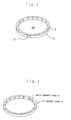
- Fig. 3 is a perspective view showing the rotor magnet 9.
- the rotor magnet 9 has two parts, a FG (Frequency Generator) magnet part A to be operated with the FG pattern coil (not shown in Fig.
- FG Frequency Generator
- Fig. 4 is a sectional view showing the magnetizing directions of the FG magnet parts A and the main magnet parts B of the rotor magnet 9.
- the magnetizing direction of the FG magnet part A is an axial direction (a direction perpendicularly crossing the FG pattern coil), and the magnetizing direction of the main magnet part B is a radial direction (a direction perpendicularly crossing the stator coil).
- the motor according to this invention is a salient pole type motor having an air gap in a radial direction and a laminated stator core structure in such a manner that the length of an air gap formed of the rotor magnet and the stator core is varied in the vicinity of the neutral part (a boundary of an N-pole and an S-pole) of the rotor magnet.
- a groove or a slit is formed at the neutral part of the rotor magnet such that the magnetic flux density distribution in the air gap closely resembles a sine wave shape.
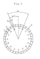
- Fig. 5 is a principle view of a three phase brushless DC motor, illustrating an example of an outer rotor type having sixteen rotor magnet poles and twelve salient poles wound with the windings of the stator core.
- symbols 4a to 41 denote stator poles; 4ca to 4cl, stator coils; and 13, 14, 15, rotor pole detectors.
- the stator assembly 4 has twelve stator poles 4a to 41 uniformly distributed at a central angle of 30° and twelve stator coils 4ca to 4cl are respectively wound on the stator poles.
- the three rotor pole detectors 13, 14, and 15 are magnetoelectric transducers, such as, for example, Hall elements, etc.
- the positions of the rotor pole detectors 13, 14, 15 are provided at substantially intermediate positions between the stator poles 4d and 4h, between the stator poles 4h and 41, and between the stator poles 41 and 4a, and hence the positions which can firmly detect the poles of the rotor magnets 9 via the air gap.
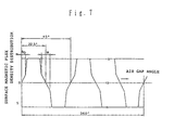
- Fig. 6 The detail of the rotor magnet 9 is shown in Fig. 6, and the surface magnetic flux density distribution of the rotor magnet 9 is shown in Fig. 7.
- the FG magnetized part (the part A of Figs. 3 and 4) magnetized at a low level integrally with the rotor magnet end face (corresponding to the lower surface in Figs. 5 and 6) in Figs. 5 and 6 is not related to the description of the principle of this invention, and hence the description will be omitted.
- the rotor magnet 9 has sixteen magnetized poles, and has the same magnetic grooves as the sixteen poles 2a to 2p. All the positions of the grooves of this embodiment are located at the pole switching points (neutral points). The angle of each groove between the pole switching points is ⁇ , where ⁇ /2 is in the N-pole and ⁇ /2 is in the S-pole.
- the surface magnetic flux density of the rotor magnet 9 becomes as shown in Fig. 7 due to the presence of such magnetic grooves 2a to 2p. That is, the surface magnetic flux density of the grooves 2a to 2p is greatly reduced as compared with the other parts, and is closer to the distribution of the sine wave shape as compared with the case which has no grooves.
- the feature of this invention is that the grooves or the slits to generate a magnetic change are formed in the rotor magnet and hence the magnetic flux density distribution in the air gap is closer to the sine wave shape. From this feature, the torque ripple is reduced without decreasing the motor efficiency and the torque constant. As a result, the irregularity of the rotation can be kept to a minimum.
- the irregularity of the rotation can be reduced without decreasing the motor efficiency and the torque constant by suitably selecting the width of the grooves of the rotor magnet and the depth of the grooves.
- the sectional shape of the groove formed on the rotor magnet is not limited only to the rectangular shape, but may be as shown by A to E in Fig. 8.
- Example A of Fig. 8 is a V-groove structure and B is a semicircular shape.
- both sides of the bottom of the groove may be rounded or both sides of the bottom of the groove may be bitten from a central angle ⁇ as in example D.
- the centre of the groove may be extended toward the opposed surface of the stator.
- the sectional shape of the groove may be suitably modified within the scope of this invention.
- the structure of the rotor magnet may be also different.
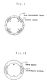
- Figs. 9 and 10 show examples of the different rotor magnets.
- the rotor magnet may be formed of a high performance magnet such as a sintered magnet or a rare earth element magnet. However, when the entire rotor magnet is manufactured by the sintered magnet or the rare earth element magnet, it becomes expensive.
- the groove of the rotor magnet becomes thin, it is weak in strength, easily deformed, and must be carefully handled.
- the example shown in Fig. 10 is strengthened by filling the groove of a rotor magnet 102 with a suitable reinforcing material 103.
- a suitable reinforcing material 103 for example, a nonmagnetic plastic material is employed.
- the rotor magnet 102 is formed of the high performance magnet such as the sintered magnet or the rare earth element magnet, a plastic magnet having low performance may be employed as the reinforcing material 103.
- the groove or the slit in the rotor magnet in which the FG magnet part A and the main magnet part B shown in Fig. 4 are integrally formed may only be in the main magnet part B, or may also extend into the FG magnet part A.
- the reason why is because the sufficient effect can be obtained by the degree that the depth of the groove is the length of the air gap (normally about 0.2 to 0.4mm), sufficiently smaller than the width of the magnetized surface of the FG magnet, and hence the influence of the FG magnet is so small as to be ignored.
- the embodiments of this invention have been described in detail. However, this invention is not limited only to the structures of the embodiments.
- the embodiment is of the outer rotor type motor.
- this invention may also be applied to an inner rotor type.
- a motor having a small irregularity in the rotation is also obtained by the similar method and is not dependent upon the driving type or the number of the poles of the magnet.
- Various modifications may also be provided in the components formed of the materials of the magnet and the reinforcing material.
- this invention may also be applied to a method of detecting the rotor position by an optical device.
- the motor torque ripple and the cogging torque is reduced without decreasing the motor efficiency and the torque constant, and even at the time of low rotation, a motor having only a small irregularity in the rotation can be provided.
- a linear drive tape using the output waveform of a rotor position detector is employed as a drive system for suppressing the generation of a switching noise at the time of commutating, and hence the device of this invention for obtaining the sine wave is very effective in this arrangement.
Landscapes
- Engineering & Computer Science (AREA)
- Power Engineering (AREA)
- Brushless Motors (AREA)
- Permanent Magnet Type Synchronous Machine (AREA)
- Permanent Field Magnets Of Synchronous Machinery (AREA)
Claims (4)
- Motoraufbau in einem Motor, der folgendes umfaßt: einen Rotormagneten (9); einen Statorkern (4); einen Luftspalt, der zwischen dem Rotormagneten und dem Statorkern in radialer Richtung derart ausgebildet ist, daß der Statoraufbau vom Schenkelpoltyp ist; und eine magnetische Rille (2a bis 2p) oder einen Schlitz, der in der Nähe eines neutralen Abschnitts (einer Grenze zwischen einem N-Pol und einem S-Pol) der Rotormagnetseite ausgebildet ist, so daß die Änderung der magnetischen Flußdichte des Luftspaltes stark einem Sinuswellenzustand ähnelt, verglichen mit derjenigen eines Luftspaltes konstanter Länge; dadurch gekennzeichnet, daß die Breite (von einem zentralen Winkel gesehen) der Rille (2a bis 2p) oder des Schlitzes in dem Magneten (9) ein Wert nahe bei 360/N° ist, wenn das kleinste gemeinsame Vielfache der Anzahl der Pole des Rotormagneten und der Anzahl der mit den Wicklungen gewickelten Schenkelpole des Statorkerns (4) gleich N ist.
- Motoraufbau nach Anspruch 1, bei welchem der Statorkern (4) keinen Wendepol hat und der Abstand der in Umfangsrichtung aufgeteilten Schenkelpole gleichmäßig ist.
- Motoraufbau nach Anspruch 1, bei welchem die Anzahl der Rillen (2a bis 2p) oder der Schlitze im Rotormagneten (9) gleich der Anzahl der Pole des Rotormagneten ist.
- Motoraufbau nach Anspruch 3, bei welchem die tiefste Tiefe der Rille (2a bis 2p) oder des Schlitzes im wesentlichen gleich der Länge des Luftspaltes ist.
Applications Claiming Priority (3)
| Application Number | Priority Date | Filing Date | Title |
|---|---|---|---|
| JP14022195 | 1995-06-07 | ||
| JP140221/95 | 1995-06-07 | ||
| JP14022195A JP3376373B2 (ja) | 1995-06-07 | 1995-06-07 | モータ構造 |
Publications (3)
| Publication Number | Publication Date |
|---|---|
| EP0748032A2 EP0748032A2 (de) | 1996-12-11 |
| EP0748032A3 EP0748032A3 (de) | 1997-05-14 |
| EP0748032B1 true EP0748032B1 (de) | 2002-05-02 |
Family
ID=15263731
Family Applications (1)
| Application Number | Title | Priority Date | Filing Date |
|---|---|---|---|
| EP96304069A Expired - Lifetime EP0748032B1 (de) | 1995-06-07 | 1996-06-04 | Anordnung eines Motors |
Country Status (4)
| Country | Link |
|---|---|
| US (1) | US6081058A (de) |
| EP (1) | EP0748032B1 (de) |
| JP (1) | JP3376373B2 (de) |
| DE (1) | DE69620948T2 (de) |
Families Citing this family (45)
| Publication number | Priority date | Publication date | Assignee | Title |
|---|---|---|---|---|
| JP3543930B2 (ja) * | 1998-11-18 | 2004-07-21 | アルプス電気株式会社 | ブラシレスモータとこのブラシレスモータを用いた磁気記録再生装置 |
| JP2000312448A (ja) * | 1999-04-26 | 2000-11-07 | Seiko Instruments Inc | 電動機 |
| JP3804343B2 (ja) * | 1999-06-29 | 2006-08-02 | 松下電器産業株式会社 | モータのコア及びそれを用いたモータ |
| EP1065777B1 (de) * | 1999-06-30 | 2004-10-13 | Shin-Etsu Chemical Co., Ltd. | Auf seltenen Erden basierender gesinterter Dauermagnet und mit einem solchen Magnet versehener Synchronmotor |
| US6664696B1 (en) * | 2000-02-29 | 2003-12-16 | Seagate Technology Llc | Tooth saturation for reduced electromagnetic harmonics |
| DE60134928D1 (de) * | 2000-07-28 | 2008-09-04 | Japan Servo | Motorisch angetriebenes System mit verzahnten Statorpolen |
| JP3995450B2 (ja) * | 2000-12-20 | 2007-10-24 | ヤマハモーターエレクトロニクス株式会社 | 永久磁石型回転電機 |
| EP1246349A3 (de) * | 2001-03-30 | 2005-09-07 | Japan Servo Co. Ltd. | Dauermagnetmotor |
| GB0111124D0 (en) * | 2001-05-05 | 2001-06-27 | Spring Gregson W M | Torque-generating apparatus |
| JP2003059254A (ja) * | 2001-08-22 | 2003-02-28 | Mitsumi Electric Co Ltd | フレキシブルディスクドライブ |
| US6917136B2 (en) | 2001-10-01 | 2005-07-12 | Magnemotion, Inc. | Synchronous machine design and manufacturing |
| US6983701B2 (en) * | 2001-10-01 | 2006-01-10 | Magnemotion, Inc. | Suspending, guiding and propelling vehicles using magnetic forces |
| US6744171B1 (en) | 2001-10-09 | 2004-06-01 | Valeo Electrical Systems, Inc. | Rotating electric machine with sloped tooth surfaces for cogging torque reduction |
| JP2003134770A (ja) * | 2001-10-23 | 2003-05-09 | Mitsumi Electric Co Ltd | フレキシブルディスクドライブ |
| JP2003153509A (ja) * | 2001-11-08 | 2003-05-23 | Matsushita Electric Ind Co Ltd | モータ |
| US6784582B1 (en) * | 2001-11-19 | 2004-08-31 | Valeo Electrical Systems, Inc. | Magnet shaping and pole concentration for reduction of cogging torque in permanent magnet motors |
| JP3680213B2 (ja) | 2002-05-30 | 2005-08-10 | デンソートリム株式会社 | 三相磁石式発電機 |
| US6727630B1 (en) * | 2002-07-31 | 2004-04-27 | Wavecrest Laboratories, Llc. | Rotary permanent magnet electric motor with varying air gap between interfacing stator and rotor elements |
| JP2004166381A (ja) * | 2002-11-12 | 2004-06-10 | Mitsubishi Electric Corp | 3相交流発電機 |
| WO2005110898A2 (en) * | 2004-05-07 | 2005-11-24 | Magnemotion, Inc. | Three-dimensional motion using single-pathway based actuators |
| JP4796674B2 (ja) * | 2005-06-24 | 2011-10-19 | 日立ビアメカニクス株式会社 | スキャナ |
| EP1907257A2 (de) * | 2005-07-22 | 2008-04-09 | Magnemotion, Inc. | Fahrwegaktivierter magnetischer fahrzeugrichtungswechsel |
| DE102005045503A1 (de) * | 2005-09-23 | 2007-03-29 | Militzer, Michael, Dr.-Ing. | Elektrische Antriebsmaschine |
| JP4175417B2 (ja) * | 2006-11-06 | 2008-11-05 | ダイキン工業株式会社 | アウターロータモータ及びその製造方法 |
| TWI343689B (en) * | 2006-12-28 | 2011-06-11 | Delta Electronics Inc | Permanent magnet rotary structure of electric machinery |
| US8616134B2 (en) | 2009-01-23 | 2013-12-31 | Magnemotion, Inc. | Transport system powered by short block linear synchronous motors |
| US9032880B2 (en) | 2009-01-23 | 2015-05-19 | Magnemotion, Inc. | Transport system powered by short block linear synchronous motors and switching mechanism |
| DE102009061032A1 (de) * | 2009-05-15 | 2010-11-18 | Tyco Electronics Belgium Ec Bvba | Magnetoelektronischer Winkelsensor, insbesondere Reluktanzresolver |
| PL2366827T3 (pl) * | 2010-03-18 | 2013-05-31 | Askoll Holding Srl | Zespół silnika i wentylatorów suszarki kondensacyjnej do bielizny oraz suszarka kondensacyjna zawierająca wspomniany zespół |
| EP2378634A1 (de) * | 2010-04-13 | 2011-10-19 | Siemens Aktiengesellschaft | Elektrische Maschine und Permanentmagnet |
| US8384262B2 (en) * | 2010-06-17 | 2013-02-26 | Fairchild Semiconductor Incorporated | Motor rotor and a motor having the same |
| DK2400634T3 (da) * | 2010-06-25 | 2013-10-14 | Siemens Ag | Generator, især til en vindmølle |
| US20120025655A1 (en) * | 2010-07-29 | 2012-02-02 | System General Corporation | Motor rotor and motor having the motor rotor |
| JP5806073B2 (ja) * | 2010-10-19 | 2015-11-10 | アスモ株式会社 | ブラシレスモータ |
| JP2012110213A (ja) * | 2010-10-25 | 2012-06-07 | Asmo Co Ltd | モータ |
| JP6275415B2 (ja) * | 2013-08-29 | 2018-02-07 | 東京パーツ工業株式会社 | ブラシレスモータ |
| EP3046801A4 (de) | 2013-09-21 | 2017-11-08 | Magnemotion, Inc. | Linearmotortransport für verpackungs- und sonstige zwecke |
| JP2016034229A (ja) * | 2014-07-29 | 2016-03-10 | 株式会社テクノクラーツ | モータ及び発電機 |
| JP6915612B2 (ja) * | 2016-04-19 | 2021-08-04 | 日本電産株式会社 | モータおよび電動パワーステアリング装置 |
| WO2018066084A1 (ja) * | 2016-10-05 | 2018-04-12 | 三菱電機株式会社 | 電動機および空気調和装置 |
| US11967871B2 (en) | 2017-09-15 | 2024-04-23 | University Of Utah Research Foundation | Cogging-torque actuator |
| JP7147327B2 (ja) * | 2018-07-26 | 2022-10-05 | 株式会社デンソー | 回転電機 |
| DE102019103127A1 (de) * | 2019-02-08 | 2020-08-13 | Minebea Mitsumi Inc. | Elektromotor |
| WO2022043972A1 (en) * | 2020-08-31 | 2022-03-03 | Padmini Vna Mechatronics Ltd. | An electric water pump with improved magnet shape |
| JP2022047120A (ja) * | 2020-09-11 | 2022-03-24 | 日本電産株式会社 | モータ |
Family Cites Families (18)
| Publication number | Priority date | Publication date | Assignee | Title |
|---|---|---|---|---|
| US3860843A (en) * | 1970-06-26 | 1975-01-14 | Matsushita Electric Industrial Co Ltd | Rotating electric machine with reduced cogging |
| GB1604121A (en) * | 1977-04-08 | 1981-12-02 | Sony Corp | Dc motors |
| US4424463A (en) * | 1981-05-27 | 1984-01-03 | Musil J Donald | Apparatus for minimizing magnetic cogging in an electrical machine |
| NL8401519A (nl) * | 1984-05-11 | 1985-12-02 | Philips Nv | Electrische motor. |
| JPS6158456A (ja) * | 1984-08-30 | 1986-03-25 | Mitsubishi Chem Ind Ltd | モ−タ− |
| US4752707A (en) * | 1986-02-06 | 1988-06-21 | Morrill Wayne J | Three-phase, one-third pitch motor |
| US5004965A (en) * | 1987-05-20 | 1991-04-02 | Canon Kabushiki Kaisha | Brushless motor with torque compensation |
| JPH0817544B2 (ja) * | 1988-06-18 | 1996-02-21 | ミネベア株式会社 | ブラシレスdcモータ |
| NL8801700A (nl) * | 1988-07-05 | 1990-02-01 | Philips Nv | Electrische meerpolige machine. |
| NZ232333A (en) * | 1990-02-01 | 1993-12-23 | Cadac Holdings Ltd | Motor stator wound with high permeability material. |
| MY113834A (en) * | 1990-06-01 | 2002-06-29 | Mitsubishi Electric Corp | Electric motor |
| JP2899998B2 (ja) * | 1991-06-04 | 1999-06-02 | 松下電器産業株式会社 | Fgマグネット固定装置 |
| JPH0525974U (ja) * | 1991-09-09 | 1993-04-02 | 松下電器産業株式会社 | 周波数発電機およびそれを具備した直流電動機 |
| US5250867A (en) * | 1991-11-20 | 1993-10-05 | General Electric Company | Permanent magnet brushless DC motor having reduced cogging |
| JP3271162B2 (ja) * | 1992-05-29 | 2002-04-02 | ソニー株式会社 | 回転検出装置 |
| JP3123283B2 (ja) * | 1993-01-29 | 2001-01-09 | 松下電器産業株式会社 | ディスク駆動装置 |
| JPH07194079A (ja) * | 1993-12-27 | 1995-07-28 | Matsushita Electric Ind Co Ltd | 永久磁石直流モータ |
| KR0129508Y1 (ko) * | 1994-08-23 | 1998-12-15 | 이형도 | 브러쉬레스 모터용 하우징 |
-
1995
- 1995-06-07 JP JP14022195A patent/JP3376373B2/ja not_active Expired - Fee Related
-
1996
- 1996-06-04 DE DE69620948T patent/DE69620948T2/de not_active Expired - Lifetime
- 1996-06-04 US US08/655,090 patent/US6081058A/en not_active Expired - Lifetime
- 1996-06-04 EP EP96304069A patent/EP0748032B1/de not_active Expired - Lifetime
Also Published As
| Publication number | Publication date |
|---|---|
| EP0748032A3 (de) | 1997-05-14 |
| DE69620948T2 (de) | 2002-11-14 |
| JP3376373B2 (ja) | 2003-02-10 |
| US6081058A (en) | 2000-06-27 |
| JPH08336249A (ja) | 1996-12-17 |
| EP0748032A2 (de) | 1996-12-11 |
| DE69620948D1 (de) | 2002-06-06 |
Similar Documents
| Publication | Publication Date | Title |
|---|---|---|
| EP0748032B1 (de) | Anordnung eines Motors | |
| US7105971B2 (en) | Permanent-magnet rotor for an inner rotor type electric rotary machine and magnet-saving type rotor for a synchronous motor | |
| EP1402617B1 (de) | Bürstenloser verniereffektmotor | |
| US4633149A (en) | Brushless DC motor | |
| US6445105B1 (en) | Axial flux machine and method of fabrication | |
| US4794293A (en) | Direct current electric motor | |
| JP2699655B2 (ja) | ブラシレスモータとその磁気センサ設置方法 | |
| US5874796A (en) | Permanent magnet D.C. motor having a radially-disposed working flux gap | |
| CN1297055C (zh) | 用于分段式定子电机的端帽组件 | |
| EP0837544B1 (de) | Motorzusammensetzung | |
| EP0160868A2 (de) | Bürstenloser Motor | |
| US4745312A (en) | Stepping motor | |
| US4703211A (en) | Slotless brushless DC motor | |
| US4072881A (en) | Axial-air-gap type semiconductor electric motor | |
| US20020175582A1 (en) | Electric drive | |
| CN1195916A (zh) | 无传感器的无刷直流电机 | |
| US6222288B1 (en) | Electric motor | |
| US6603635B1 (en) | Motor structure for use with optical disks | |
| CN1178609A (zh) | 具有最小净余径向力和低齿槽效应转矩的高速十极/十二槽直流无刷电动机 | |
| JPS5855747B2 (ja) | ブラシレスチヨクリユウモ−タ | |
| JP2002218717A (ja) | Dcモータ | |
| US20040150286A1 (en) | Motor | |
| JP3840715B2 (ja) | 永久磁石形同期電動機 | |
| KR100427791B1 (ko) | 다상모터 | |
| EP1153472A1 (de) | Davermagnet-gleichstrommotor mit radialem luftspalt. |
Legal Events
| Date | Code | Title | Description |
|---|---|---|---|
| PUAI | Public reference made under article 153(3) epc to a published international application that has entered the european phase |
Free format text: ORIGINAL CODE: 0009012 |
|
| AK | Designated contracting states |
Kind code of ref document: A2 Designated state(s): DE GB |
|
| PUAL | Search report despatched |
Free format text: ORIGINAL CODE: 0009013 |
|
| AK | Designated contracting states |
Kind code of ref document: A3 Designated state(s): DE GB |
|
| 17P | Request for examination filed |
Effective date: 19971031 |
|
| 17Q | First examination report despatched |
Effective date: 19990315 |
|
| GRAG | Despatch of communication of intention to grant |
Free format text: ORIGINAL CODE: EPIDOS AGRA |
|
| GRAH | Despatch of communication of intention to grant a patent |
Free format text: ORIGINAL CODE: EPIDOS IGRA |
|
| GRAH | Despatch of communication of intention to grant a patent |
Free format text: ORIGINAL CODE: EPIDOS IGRA |
|
| REG | Reference to a national code |
Ref country code: GB Ref legal event code: IF02 |
|
| GRAA | (expected) grant |
Free format text: ORIGINAL CODE: 0009210 |
|
| AK | Designated contracting states |
Kind code of ref document: B1 Designated state(s): DE GB |
|
| REG | Reference to a national code |
Ref country code: GB Ref legal event code: FG4D |
|
| REF | Corresponds to: |
Ref document number: 69620948 Country of ref document: DE Date of ref document: 20020606 |
|
| PLBE | No opposition filed within time limit |
Free format text: ORIGINAL CODE: 0009261 |
|
| STAA | Information on the status of an ep patent application or granted ep patent |
Free format text: STATUS: NO OPPOSITION FILED WITHIN TIME LIMIT |
|
| 26N | No opposition filed |
Effective date: 20030204 |
|
| PGFP | Annual fee paid to national office [announced via postgrant information from national office to epo] |
Ref country code: GB Payment date: 20080604 Year of fee payment: 13 |
|
| GBPC | Gb: european patent ceased through non-payment of renewal fee |
Effective date: 20090604 |
|
| PG25 | Lapsed in a contracting state [announced via postgrant information from national office to epo] |
Ref country code: GB Free format text: LAPSE BECAUSE OF NON-PAYMENT OF DUE FEES Effective date: 20090604 |
|
| PGFP | Annual fee paid to national office [announced via postgrant information from national office to epo] |
Ref country code: DE Payment date: 20100602 Year of fee payment: 15 |
|
| REG | Reference to a national code |
Ref country code: DE Ref legal event code: R119 Ref document number: 69620948 Country of ref document: DE Effective date: 20120103 |
|
| PG25 | Lapsed in a contracting state [announced via postgrant information from national office to epo] |
Ref country code: DE Free format text: LAPSE BECAUSE OF NON-PAYMENT OF DUE FEES Effective date: 20120103 |