EP0748100A2 - Dispositif de surveillance de câbles à terminaisons de branchements multiples - Google Patents
Dispositif de surveillance de câbles à terminaisons de branchements multiples Download PDFInfo
- Publication number
- EP0748100A2 EP0748100A2 EP96304177A EP96304177A EP0748100A2 EP 0748100 A2 EP0748100 A2 EP 0748100A2 EP 96304177 A EP96304177 A EP 96304177A EP 96304177 A EP96304177 A EP 96304177A EP 0748100 A2 EP0748100 A2 EP 0748100A2
- Authority
- EP
- European Patent Office
- Prior art keywords
- detection conductor
- voltage
- termination
- detection
- cable
- Prior art date
- Legal status (The legal status is an assumption and is not a legal conclusion. Google has not performed a legal analysis and makes no representation as to the accuracy of the status listed.)
- Granted
Links
Images

Classifications
-
- H—ELECTRICITY
- H04—ELECTRIC COMMUNICATION TECHNIQUE
- H04M—TELEPHONIC COMMUNICATION
- H04M3/00—Automatic or semi-automatic exchanges
- H04M3/22—Arrangements for supervision, monitoring or testing
- H04M3/26—Arrangements for supervision, monitoring or testing with means for applying test signals or for measuring
- H04M3/28—Automatic routine testing ; Fault testing; Installation testing; Test methods, test equipment or test arrangements therefor
-
- G—PHYSICS
- G01—MEASURING; TESTING
- G01R—MEASURING ELECTRIC VARIABLES; MEASURING MAGNETIC VARIABLES
- G01R31/00—Arrangements for testing electric properties; Arrangements for locating electric faults; Arrangements for electrical testing characterised by what is being tested not provided for elsewhere
- G01R31/50—Testing of electric apparatus, lines, cables or components for short-circuits, continuity, leakage current or incorrect line connections
- G01R31/58—Testing of lines, cables or conductors
Definitions
- the present invention relates to the monitoring of communications cables for damage.
- Telephone and communication cables are subject to damage and wear from environmental conditions and man made causes. Severe weather conditions such as high winds, snow, icing, rain, floods, and lightning can damage exposed cables. Damage can occur from nearby construction or by vandalism. The ingress of rain or ground water into the cable core or splice closure at damage locations is a major cause of outages, Every effort is made to keep the cable in good repair and water out of the cable structure.
- Maintenance monitoring systems have been used to detect and provide early warning of cable trouble.
- a DC voltage is applied to one end of a detection conductor extending the length of the cable and currents in the detection conductor are monitored to detect faults in the cable.
- the termination resistor at the remote end of the monitored conductor(s) creates a continuous loop back path through which a "nominal" monitoring current flows.
- the continuous loop current is used to check for line continuity to the end of the cable section.
- a monitoring current "window” is established. If the loop current drops below a minimum value, which is typically set at half of the nominal loop current as established by the termination resistor, then the line is considered “open” and is not electrically continuous for monitoring purposes. If the loop current exceeds a maximum level, as a result of a "fault" at a point along the monitored detection conductor(s), then the cable is considered damaged and in need of repair.
- the increase in current from the nominal set point to cause "fault” alarm is on the order of 1 mA while the decrease in current from the nominal set point to cause an "open” alarm is about 0.25 mA.
- the loop back termination resistor for the earlier system was chosen to provide a small nominal loop current of about 0.5 mA.
- the "'open" condition was established when the current decreased by about 0.25 mA. For a typical system, this would require an increase in the loop resistance of about 250,000 ohms before an "open" would be detected. Due to this lack of sensitivlty to in series resistance increases, an increase of resistance in a monitored conductor joint on the order of 10 ohms, which is considered significant, can not be detected.
- the present invention is concerned with mitigating these limitations and problems.
- a method of monitoring a communications cable for damage the cable having a detection conductor therealong with a monitored end and a remote end, the method including the steps of applying to the monitored end of the detection conductor a DC voltage with respect to ground and monitoring currents in the detection conductor to detect faults in the cable, characterized by:
- a monitoring system for a communications cable having a monitored end, a remote end and a detection conductor extending along the cable from the monitored end to the remote end, the system comprising means for applying a DC voltage to the detection conductor at the monitored end and means for monitoring currents in the detection conductor, characterized by:
- the terminating resistor of the earlier systems is thus replaced with a termination circuit placed at the end of the detection conductor.
- the termination circuit appears as an open circuit.
- any loop current is a direct result of a resistive fault along the detection conductor which is directly caused by cable damage.
- This allows, in theory, an unlimited number of branch cables to be connected to, and monitored, along with the main cable.
- the inventive method is applicable to the monitoring of a communications cable system including a main cable and a plurality of branch cables, each with a detection conductor extending therealong.
- the detection conductors are electrically connected, and a plurality of branch termination means are connected to the respective branch detection conductors at terminal ends of the respective branches.
- the DC voltage is applied to the detection conductor of the main cable.
- This application of the method is characterized by; actuating the branch termination means in response to the selective alteration of the DC voltage and causing the branch termination means to connect to ground the individual branch detection conductors individually and at separate times.
- the monitoring system is likewise applicable to a communications cable system including a main cable with a monitored end and a plurality of branch cables coupled to the main cable, with each of the main and branch cables having a detection conductor extending therealong and with the detection conductors electrically connected.
- the DC voltage is applied to the monitored end of the main cable detection conductor and the current monitoring means monitors currents in the main cable detection conductor.
- the system is characterized by;
- the method and apparatus thus use a termination circuit placed at the end of the detection conductors on the main cable and every monitored branch cable.
- the termination circuit appears as an open circuit. There is no requirement for a nominal loop current to monitor continuity which allows, in theory, an unlimited number of branch cables to be connected to, and monitored along, with the main cable.
- the step of altering the DC voltage applied to the detection conductor may include reversing the polarity of the DC voltage to activate the termination circuits.
- the DC voltage may also be increased to a level adequate to test for resistive faults and to power all of the termination circuits.
- a coded signal may be applied to the detection conductor by the actuated termination circuit and monitored at the monitored end of the detection conductor.
- the branch termination circuits may be actuated simultaneously, and configured to connect the respective detection conductors to ground in a timed sequence.
- the branch termination means may be actuated in sequence with coded signals applied to the detection conductor of the main conductor.
- reversing the DC monitoring polarity and signaling a selected termination activates the termination to perform a series of functional tests.
- One such test is a loop test which places a direct or a low resistance short across the end of the detection conductor for a timed period. This results in a high level loop current which is measured and used to calculate the total detection conductor resistance. The resulting high loop current allows a loop resistance measurement to within a fraction of an ohm. The detection conductor resistance along with any increase in conductor joint resistance can be accurately measured and tracked thus providing important information on the cable condition.
- a second test transmits a coded signal simulating a triggered splice sensor unit for a predetermined time. The signal is detected and decoded to verify proper operation of end to end coded signaling. After competing the test cycle, the termination circuit turns off and the next termination to be tested is signaled.
- the invention thus provides a method and apparatus for monitoring a cable for faults without a continuous loop current. Consequently it may be used means to monitor a main cable along with a large number branch cables. Preferred embodiments of the invention also perform a rigorous loop test on every cable section and can detect small changes in the series resistance of the monitored conductors to effectively detect defective conductor joints.
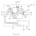
- Figure 1 illustrates a prior art distribution cable system 10.
- the system includes a main cable 12 and a large number of branch cables 14 extending from the main cable and connected to it by splices 16.
- the system includes termination resistors 18 at the remote ends of the main cable and each branch cable to monitor for continuity of the respective cable sections.
- the resistors are connected to detection conductors, e.g. cable jackets or special moisture detecting conductors, extending along the cables.
- the detection conductors are electrically connected at the splices 16.
- a monitoring station 19 at the inner end of the main cable applies a DC voltage to the detection conductor. This voltage produces a loop current through the detection conductors, the resistors and a return path, which may be ground or a second conductor. The loop current is monitored to monitor the condition of the cable.
- FIG 3 illustrates a splice enclosure 23. This is essentially the same as the splice monitoring arrangement described in United States patents 4,480,251 and 5,077,526, referred to above.
- a metallic armor layer 24 is used as a detection conductor providing complete end to end monitoring of the cable.
- the armor layer is connected to the monitoring station 19 and the termination circuit 22 at opposite ends of the main cable as shown in Figure 2.
- the branch cable detection conductors are connected at their remote ends to respective termination circuits 22 and to other detection conductors at the splices 16.
- the monitoring station 19 includes a DC voltage source 20 with a polarity reversing capability, means for selectively altering the magnitude of the voltage. This allows the voltage to be altered as an actuating signal to the termination circuits.
- the monitoring station also includes a current monitoring component 21.
- each splice enclosure 23 there is a remote splice sensor unit (SSU) 26, connected to a moisture detection tape 28 that is wrapped around the splice bundle.
- SSU remote splice sensor unit
- the remote sensor unit When water contacts the tape, the remote sensor unit is triggered to transmit a 32-baud digitally encoded alarm signal to the office terminal through the cable armor.
- the monitoring station intercepts, decodes, and displays the exact location of the trouble.
- the termination may also transmit a digitally coded number corresponding to a measured quantity such as resistance, voltage, pressure, temperature etc.
- a digitally coded number corresponding to a measured quantity such as resistance, voltage, pressure, temperature etc.
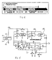
- the circuit includes a protection circuit 30 that protects the termination against high voltage transients and the like. It has a terminal 32 coupled to the detection conductor and a return path terminal 34 connected to either the return conductor or a ground return path.
- the protection circuit has a ground connection 36.
- a signal line 38 leads from the protection circuit to the anode of a diode D1.
- the cathode of diode D1 is connected to the anode of zener diode Z1.
- the anode of the zener is connected to a grounded capacitor C1 and to the input of a voltage regulator 46.
- the voltage regulator is a power supply for a low pass filter 48 and a decoder circuit 50.
- the input to the low pass filter is taken from the signal line 38 through an RC filter consisting of capacitor C5 and resistor R7.
- the output of the low pass filter 48 is passed to the input of the decoder circuit 50.
- the decoder circuit output is connected to a diode D3, the cathode which is connected to ground through a resistor R6.
- the output of the diode is also connected to the gate of a mosfet Q4 connected between ground and a circuit ground line 61.
- the ground line 61 is also connected to ground through a capacitor C3.
- Line 61 leads to an emitter follower voltage regulator formed by a transistor Q1, a resistor R2 connecting the collector and base of the transistor and zener Z2 and capacitor C2 connecting the base to the line 61.
- the collector of transistor Q1 is connected to the signal line 38 through diode D1.
- the transistor emitter is connected through a diode D2 to a microprocessor 76.
- the microprocessor when turned on, delivers a positive output to a diode D4 which is connected to the gate of mosfet Q4.
- the microprocessor is also connected to a modulator circuit 82 including a resistor R5 connected to the base of a transistor Q2.
- the transistor emitter is connected to the line 61 while its collector is connected through a resistor R3 to the emitter of transistor Q1.
- the microprocessor has a further output connected through a resistor R4 to the base of a transistor Q3.
- the emitter of the transmitter is connected to line 61, while its collector is connected through a test resistor R1 to the signal line 38 through diode D1.
- a positive voltage of about 80 V DC is applied to the circuit.
- Dl is forward biased and the zener diode ZI conducts applying about 20 V DC across the voltage regulator circuit.
- the voltage regulator outputs a constant 12 V DC, powering the low pass filter 48 and decode circuit 50.
- These circuits use low power microwatt ( ⁇ W) integrated circuits to minimize the loading on the monitored line. This allows a large number of termination circuits to be powered up simultaneously.
- the terminal equipment then transmits a Manchester binary address code to all terminations circuits on the line.
- the signal is capacitively coupled through C5 to the low pass filter which removes noise and reshapes the pulses before passing them on to the decode circuit.
- the decode circuit reads the binary address code and compares it to the preset address of the termination.
- the decode circuit If the address code matches the internal code, the decode circuit outputs a positive voltage to diode D3 which becomes forward biased applying a positive voltage to the gate of the mosfet Q4.
- the mosfet turns on thereby applying the line voltage across the emitter follower voltage regulator formed by Q1, R2, Z2 and C2.
- the output of the regulator is applied via D2 to the microprocessor 76 which begins a preprogrammed test sequence.
- the microprocessor outputs a positive voltage to the base of mosfet Q4 through diode D4 to keep the circuit turned on. At this time the line voltage is reduced to the about 50 volts thereby turning off the decode circuit while the test circuit remains operational.
- the microprocessor outputs a pulsed address code to the modulator circuit formed by R5, Q2, and R3. This sends a return response to the terminal equipment thereby verifying the responding termination address code. After repeating the address code for about 10 seconds, the microprocessor outputs a positive voltage to resistor R4 turning on Q3 which places a test resistor R1 across the line. This results in a line current test of up to 15 mA for several seconds to allow the terminal equipment to compute the line resistance and test the splice joins for high resistance. After completing the test cycle the microprocessor removes the positive voltage to Q4 thereby switching off the entire termination circuit.
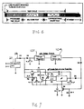
- FIG. 6 An alternative embodiment of the invention is illustrated in Figures 6 and 7.
- the termination does not respond to an address code but instead operates after a predetermined time delay.
- the termination may also transmit a digitally coded number corresponding to a measured quantity such as resistance, voltage, pressure, temperature etc.
- a digitally coded number corresponding to a measured quantity such as resistance, voltage, pressure, temperature etc.
- the alternative sequenced termination circuit 96 includes a protection circuit 30, signal line 38 and diode D1 like those of the circuit of Figure 4.
- the output of diode D1 is delivered through a diode D5 to a grounded capacitor C1 and the input of a voltage regulator 102.
- the voltage regulator output is delivered to a time delay circuit 104 which delivers its output to diode D3 corresponding to diode D3 of the embodiment of Figure 5.
- a positive voltage of about 50 V DC is applied to the monitored detection line.
- Diodes Dl and D5 are forward biased and the line voltage is applied to the voltage regulator 102 of the low power time delay circuit 104.
- the voltage regulator provides a constant voltage of about 5 V DC to the time delay circuit.
- the time delay circuit activates and begins a time delay countdown. At the end of the predetermined countdown, the time delay circuit outputs a single positive pulse to diode D3 which turns on mosfet Q4. The rest of the circuit the operates as described in the addressable termination circuit.
- the terminations are designed sucn tnat tne time delays are programmed to avoid test cycle overlap as the termination operate in sequence.
Landscapes
- Physics & Mathematics (AREA)
- General Physics & Mathematics (AREA)
- Engineering & Computer Science (AREA)
- Signal Processing (AREA)
- Testing Of Short-Circuits, Discontinuities, Leakage, Or Incorrect Line Connections (AREA)
- Monitoring And Testing Of Transmission In General (AREA)
- Cable Transmission Systems, Equalization Of Radio And Reduction Of Echo (AREA)
Applications Claiming Priority (2)
| Application Number | Priority Date | Filing Date | Title |
|---|---|---|---|
| CA002151094A CA2151094C (fr) | 1995-06-06 | 1995-06-06 | Dispositif de surveillance de reseau de cables a ramifications multiples |
| CA2151094 | 1995-06-06 |
Publications (3)
| Publication Number | Publication Date |
|---|---|
| EP0748100A2 true EP0748100A2 (fr) | 1996-12-11 |
| EP0748100A3 EP0748100A3 (fr) | 1997-06-18 |
| EP0748100B1 EP0748100B1 (fr) | 2000-01-05 |
Family
ID=4156003
Family Applications (1)
| Application Number | Title | Priority Date | Filing Date |
|---|---|---|---|
| EP96304177A Expired - Lifetime EP0748100B1 (fr) | 1995-06-06 | 1996-06-06 | Dispositif de surveillance de câbles à terminaisons de branchements multiples |
Country Status (5)
| Country | Link |
|---|---|
| US (1) | US5708364A (fr) |
| EP (1) | EP0748100B1 (fr) |
| AT (1) | ATE188586T1 (fr) |
| CA (1) | CA2151094C (fr) |
| DE (1) | DE69605979T2 (fr) |
Cited By (2)
| Publication number | Priority date | Publication date | Assignee | Title |
|---|---|---|---|---|
| EP1091218A3 (fr) * | 1999-10-06 | 2003-04-09 | Norscan Instruments, Ltd. | Terminaison de cable à courant constant pour des signaux de localisation de cable |
| CN113687134A (zh) * | 2021-08-25 | 2021-11-23 | 绵阳市维博电子有限责任公司 | 一种带综合诊断功能的电流传感器电路及电流传感器 |
Families Citing this family (28)
| Publication number | Priority date | Publication date | Assignee | Title |
|---|---|---|---|---|
| GB9516304D0 (en) * | 1995-08-09 | 1995-10-11 | Flight Refueling Ltd | Detection and location of current leakage paths and detection of oscillations |
| FR2761175B1 (fr) * | 1997-03-20 | 1999-04-30 | Schneider Automation | Bus de communication numerique assurant la connexion de modules electroniques |
| US5903221A (en) * | 1997-11-24 | 1999-05-11 | At&T Corp. | Method and apparatus for determining the moisture level in a buried splice |
| FI108758B (fi) * | 1998-09-11 | 2002-03-15 | Nokia Corp | Menetelmä ja järjestelmä hälytysten välittämiseksi |
| FR2783926B1 (fr) * | 1998-09-28 | 2001-10-19 | Socrat | Procede et dispositif pour la localisation d'un defaut d'isolement d'un cable |
| US6433557B1 (en) * | 2000-12-21 | 2002-08-13 | Eaton Corporation | Electrical system with capacitance tap and sensor for on-line monitoring the state of high-voltage insulation and remote monitoring device |
| US6489782B1 (en) * | 2000-12-21 | 2002-12-03 | Eaton Corporation | Electrical system with a stand-off insulator-sensor for on-line partial discharge monitoring of the state of high-voltage insulation |
| US6504382B2 (en) * | 2000-12-21 | 2003-01-07 | Eaton Corporation | Electrical system with a stress shield system for partial discharge on-line monitoring of the state of high-voltage insulation |
| US6810337B1 (en) * | 2002-03-07 | 2004-10-26 | Bellsouth Intellectual Property Corporation | Systems and methods for tracking the age of air pressure and flow alarm conditions within a pressurized cable network |
| DE10330330B4 (de) * | 2003-07-04 | 2006-04-20 | European Advanced Superconductors Gmbh & Co. Kg | Verfahren und Vorrichtung zur Pfüfung der Isolierung eines strangförmigen Leiters |
| GB0407198D0 (en) * | 2004-03-30 | 2004-05-05 | British Telecomm | Joint fault detection |
| US20100046940A1 (en) * | 2008-08-22 | 2010-02-25 | Generonix, Inc. | Reliable Power Source for Fiber to Home Network Termination and Other Critical Applications |
| US8624578B2 (en) * | 2009-06-04 | 2014-01-07 | Veris Industries, Llc | Branch current monitor with configuration |
| US9632275B2 (en) | 2012-06-15 | 2017-04-25 | Commscope Technologies Llc | Secure jacket |
| US9506952B2 (en) | 2012-12-31 | 2016-11-29 | Veris Industries, Llc | Power meter with automatic configuration |
| US9964583B2 (en) | 2013-02-22 | 2018-05-08 | Smartkable Llc | Method and apparatus for predicting life cycle of a splice |
| WO2014130806A1 (fr) * | 2013-02-22 | 2014-08-28 | SmartKable, LLC | Procédé et appareil pour surveiller l'état d'une épissure |
| US10840698B2 (en) | 2017-09-22 | 2020-11-17 | Chengli Li | Leakage current detection and protection device for power cord |
| US10557883B2 (en) * | 2017-09-22 | 2020-02-11 | Chengli Ll | Leakage current detection and protection device for power cord |
| US11243265B2 (en) | 2017-09-22 | 2022-02-08 | Chengli Li | Intelligent leakage current detection and interruption device for power cord |
| US11005260B2 (en) | 2017-09-22 | 2021-05-11 | Chengli Li | Leakage current detection and interruption device for power cord, and power connector and appliance employing the same |
| US11536777B2 (en) | 2017-09-22 | 2022-12-27 | Chengli Li | Intelligent leakage current detection and interruption device for power cord |
| US11258245B2 (en) | 2017-09-28 | 2022-02-22 | Chengli Li | Intelligent leakage current detection and interruption device for power cord |
| US11600984B1 (en) | 2022-02-23 | 2023-03-07 | Chengli Li | Leakage current detection and interruption device for power cord and related electrical connectors and electrical appliances |
| US12237665B2 (en) | 2022-02-23 | 2025-02-25 | Chengli Li | Leakage current detection and interruption device for power cord and related electrical connectors and electrical appliances |
| US12206231B2 (en) | 2022-03-22 | 2025-01-21 | Chengli Li | Leakage current detection and interruption device for power cord and related electrical connectors and electrical appliances |
| US12046893B2 (en) | 2022-06-08 | 2024-07-23 | Chengli Li | Leakage current detection and interruption device for power cord and related electrical connectors and electrical appliances |
| US20260039328A1 (en) * | 2024-07-30 | 2026-02-05 | Texas Instruments Incorporated | Methods and apparatus to characterize cable faults |
Family Cites Families (9)
| Publication number | Priority date | Publication date | Assignee | Title |
|---|---|---|---|---|
| US2752590A (en) * | 1954-03-01 | 1956-06-26 | Specialties Dev Corp | Insulation failure detector for electric cables |
| CA1168707A (fr) * | 1980-04-22 | 1984-06-05 | Norscan Instruments Ltd. | Capteur-indicateur d'infiltration d'eau pour cables electriques et leurs epissures |
| GB2082406B (en) * | 1980-04-22 | 1984-06-13 | Domenco Wayne David | Monitoring electrical cables and joints for the ingress of moisture |
| US4446421A (en) * | 1981-06-22 | 1984-05-01 | Grumman Aerospace Corporation | Apparatus and method for locating faults in cables |
| CA1317355C (fr) * | 1988-03-30 | 1993-05-04 | David E. Vokey | Systeme de detection de defaut de cable |
| US5077526A (en) * | 1988-03-30 | 1991-12-31 | Automated Light Technologies, Inc. | Cable failure detection system |
| US5066919A (en) * | 1990-04-03 | 1991-11-19 | Ford Motor Company | Fault detection and isolation in automotive wiring harness by network analysis method |
| US5179342A (en) * | 1991-02-11 | 1993-01-12 | Westinghouse Electric Corp. | Superconductor quench measuring device which evaluates reflected pulses |
| US5612624A (en) * | 1996-01-24 | 1997-03-18 | Clinton Instrument Company | Apparatus for testing the insulation of an electrical conductor |
-
1995
- 1995-06-06 CA CA002151094A patent/CA2151094C/fr not_active Expired - Lifetime
- 1995-08-02 US US08/510,239 patent/US5708364A/en not_active Expired - Lifetime
-
1996
- 1996-06-06 EP EP96304177A patent/EP0748100B1/fr not_active Expired - Lifetime
- 1996-06-06 DE DE69605979T patent/DE69605979T2/de not_active Expired - Lifetime
- 1996-06-06 AT AT96304177T patent/ATE188586T1/de not_active IP Right Cessation
Cited By (3)
| Publication number | Priority date | Publication date | Assignee | Title |
|---|---|---|---|---|
| EP1091218A3 (fr) * | 1999-10-06 | 2003-04-09 | Norscan Instruments, Ltd. | Terminaison de cable à courant constant pour des signaux de localisation de cable |
| CN113687134A (zh) * | 2021-08-25 | 2021-11-23 | 绵阳市维博电子有限责任公司 | 一种带综合诊断功能的电流传感器电路及电流传感器 |
| CN113687134B (zh) * | 2021-08-25 | 2024-02-13 | 绵阳市维博电子有限责任公司 | 一种带综合诊断功能的电流传感器电路及电流传感器 |
Also Published As
| Publication number | Publication date |
|---|---|
| CA2151094C (fr) | 1999-05-11 |
| EP0748100A3 (fr) | 1997-06-18 |
| DE69605979D1 (de) | 2000-02-10 |
| EP0748100B1 (fr) | 2000-01-05 |
| DE69605979T2 (de) | 2000-08-03 |
| ATE188586T1 (de) | 2000-01-15 |
| US5708364A (en) | 1998-01-13 |
| CA2151094A1 (fr) | 1996-12-07 |
Similar Documents
| Publication | Publication Date | Title |
|---|---|---|
| EP0748100B1 (fr) | Dispositif de surveillance de câbles à terminaisons de branchements multiples | |
| CA1168707A (fr) | Capteur-indicateur d'infiltration d'eau pour cables electriques et leurs epissures | |
| AU766993B2 (en) | Method and device for locating an insulation fault in an electric cable | |
| US6292541B1 (en) | Line shunt and ground fault apparatus method | |
| EP0168410B1 (fr) | Unite terminale d'entretien amelioree | |
| US4415779A (en) | Methods of and apparatus for testing telephone subscriber loop to locate a fault relative to a reference point | |
| JPS64753B2 (fr) | ||
| CA1222800A (fr) | Mecanisme de deconnexion de terminaux et de detection de defaillances dans les fils | |
| US4922183A (en) | Methods, systems and apparatus for detecting changes in variables | |
| AU617408B2 (en) | Dc termination circuit for subscriber cables | |
| CA2080133A1 (fr) | Dispositif de protection pour appareils, machines et installations electriques | |
| US6507277B2 (en) | Danger signalling system | |
| US5198775A (en) | Device for verifying the water tightness of metallically sheathed cable networks | |
| JP2992339B2 (ja) | 金属被覆ケーブル網の密閉性検査装置 | |
| US5862200A (en) | Ground fault detector for T1 span equipment | |
| AU610031B2 (en) | Submarine optical cable fault location | |
| JP2931232B2 (ja) | 相確認用補助装置 | |
| GB2082406A (en) | Monitoring electrical cables and joints for the ingress of moisture | |
| US6657436B1 (en) | Sheath monitoring technique | |
| JPS6191536A (ja) | 自己支持形光フアイバケ−ブルの断線検出装置 | |
| SU1758881A1 (ru) | Способ определени места замыкани на землю в цепи дистанционного питани телемеханики системы передачи |
Legal Events
| Date | Code | Title | Description |
|---|---|---|---|
| PUAI | Public reference made under article 153(3) epc to a published international application that has entered the european phase |
Free format text: ORIGINAL CODE: 0009012 |
|
| AK | Designated contracting states |
Kind code of ref document: A2 Designated state(s): AT BE DE DK ES FR GB GR IE IT NL PT SE |
|
| PUAL | Search report despatched |
Free format text: ORIGINAL CODE: 0009013 |
|
| AK | Designated contracting states |
Kind code of ref document: A3 Designated state(s): AT BE DE DK ES FR GB GR IE IT NL PT SE |
|
| 17P | Request for examination filed |
Effective date: 19971208 |
|
| GRAG | Despatch of communication of intention to grant |
Free format text: ORIGINAL CODE: EPIDOS AGRA |
|
| 17Q | First examination report despatched |
Effective date: 19990301 |
|
| GRAG | Despatch of communication of intention to grant |
Free format text: ORIGINAL CODE: EPIDOS AGRA |
|
| GRAH | Despatch of communication of intention to grant a patent |
Free format text: ORIGINAL CODE: EPIDOS IGRA |
|
| GRAH | Despatch of communication of intention to grant a patent |
Free format text: ORIGINAL CODE: EPIDOS IGRA |
|
| GRAH | Despatch of communication of intention to grant a patent |
Free format text: ORIGINAL CODE: EPIDOS IGRA |
|
| GRAA | (expected) grant |
Free format text: ORIGINAL CODE: 0009210 |
|
| AK | Designated contracting states |
Kind code of ref document: B1 Designated state(s): AT BE DE DK ES FR GB GR IE IT NL PT SE |
|
| PG25 | Lapsed in a contracting state [announced via postgrant information from national office to epo] |
Ref country code: SE Free format text: THE PATENT HAS BEEN ANNULLED BY A DECISION OF A NATIONAL AUTHORITY Effective date: 20000105 Ref country code: NL Free format text: LAPSE BECAUSE OF FAILURE TO SUBMIT A TRANSLATION OF THE DESCRIPTION OR TO PAY THE FEE WITHIN THE PRESCRIBED TIME-LIMIT Effective date: 20000105 Ref country code: GR Free format text: LAPSE BECAUSE OF NON-PAYMENT OF DUE FEES Effective date: 20000105 Ref country code: ES Free format text: THE PATENT HAS BEEN ANNULLED BY A DECISION OF A NATIONAL AUTHORITY Effective date: 20000105 Ref country code: BE Free format text: LAPSE BECAUSE OF FAILURE TO SUBMIT A TRANSLATION OF THE DESCRIPTION OR TO PAY THE FEE WITHIN THE PRESCRIBED TIME-LIMIT Effective date: 20000105 Ref country code: AT Free format text: LAPSE BECAUSE OF FAILURE TO SUBMIT A TRANSLATION OF THE DESCRIPTION OR TO PAY THE FEE WITHIN THE PRESCRIBED TIME-LIMIT Effective date: 20000105 |
|
| REF | Corresponds to: |
Ref document number: 188586 Country of ref document: AT Date of ref document: 20000115 Kind code of ref document: T |
|
| REF | Corresponds to: |
Ref document number: 69605979 Country of ref document: DE Date of ref document: 20000210 |
|
| REG | Reference to a national code |
Ref country code: IE Ref legal event code: FG4D |
|
| ITF | It: translation for a ep patent filed | ||
| PG25 | Lapsed in a contracting state [announced via postgrant information from national office to epo] |
Ref country code: PT Free format text: LAPSE BECAUSE OF FAILURE TO SUBMIT A TRANSLATION OF THE DESCRIPTION OR TO PAY THE FEE WITHIN THE PRESCRIBED TIME-LIMIT Effective date: 20000405 Ref country code: DK Free format text: LAPSE BECAUSE OF FAILURE TO SUBMIT A TRANSLATION OF THE DESCRIPTION OR TO PAY THE FEE WITHIN THE PRESCRIBED TIME-LIMIT Effective date: 20000405 |
|
| ET | Fr: translation filed | ||
| NLV1 | Nl: lapsed or annulled due to failure to fulfill the requirements of art. 29p and 29m of the patents act | ||
| PG25 | Lapsed in a contracting state [announced via postgrant information from national office to epo] |
Ref country code: IE Free format text: LAPSE BECAUSE OF NON-PAYMENT OF DUE FEES Effective date: 20000606 |
|
| PLBE | No opposition filed within time limit |
Free format text: ORIGINAL CODE: 0009261 |
|
| STAA | Information on the status of an ep patent application or granted ep patent |
Free format text: STATUS: NO OPPOSITION FILED WITHIN TIME LIMIT |
|
| 26N | No opposition filed | ||
| REG | Reference to a national code |
Ref country code: IE Ref legal event code: MM4A |
|
| REG | Reference to a national code |
Ref country code: GB Ref legal event code: IF02 |
|
| PGFP | Annual fee paid to national office [announced via postgrant information from national office to epo] |
Ref country code: FR Payment date: 20100706 Year of fee payment: 15 |
|
| PGFP | Annual fee paid to national office [announced via postgrant information from national office to epo] |
Ref country code: IT Payment date: 20100621 Year of fee payment: 15 |
|
| PGFP | Annual fee paid to national office [announced via postgrant information from national office to epo] |
Ref country code: GB Payment date: 20100618 Year of fee payment: 15 Ref country code: DE Payment date: 20100625 Year of fee payment: 15 |
|
| GBPC | Gb: european patent ceased through non-payment of renewal fee |
Effective date: 20110606 |
|
| PG25 | Lapsed in a contracting state [announced via postgrant information from national office to epo] |
Ref country code: IT Free format text: LAPSE BECAUSE OF NON-PAYMENT OF DUE FEES Effective date: 20110606 |
|
| REG | Reference to a national code |
Ref country code: FR Ref legal event code: ST Effective date: 20120229 |
|
| REG | Reference to a national code |
Ref country code: DE Ref legal event code: R119 Ref document number: 69605979 Country of ref document: DE Effective date: 20120103 |
|
| PG25 | Lapsed in a contracting state [announced via postgrant information from national office to epo] |
Ref country code: DE Free format text: LAPSE BECAUSE OF NON-PAYMENT OF DUE FEES Effective date: 20120103 Ref country code: FR Free format text: LAPSE BECAUSE OF NON-PAYMENT OF DUE FEES Effective date: 20110630 |
|
| PG25 | Lapsed in a contracting state [announced via postgrant information from national office to epo] |
Ref country code: GB Free format text: LAPSE BECAUSE OF NON-PAYMENT OF DUE FEES Effective date: 20110606 |