EP0748134A2 - Récepteur-radio d'appel sélectif à capabilité d'affichage de message - Google Patents
Récepteur-radio d'appel sélectif à capabilité d'affichage de message Download PDFInfo
- Publication number
- EP0748134A2 EP0748134A2 EP96109011A EP96109011A EP0748134A2 EP 0748134 A2 EP0748134 A2 EP 0748134A2 EP 96109011 A EP96109011 A EP 96109011A EP 96109011 A EP96109011 A EP 96109011A EP 0748134 A2 EP0748134 A2 EP 0748134A2
- Authority
- EP
- European Patent Office
- Prior art keywords
- message
- display
- character string
- displayed
- switch
- Prior art date
- Legal status (The legal status is an assumption and is not a legal conclusion. Google has not performed a legal analysis and makes no representation as to the accuracy of the status listed.)
- Granted
Links
Images


Classifications
-
- G—PHYSICS
- G08—SIGNALLING
- G08B—SIGNALLING SYSTEMS, e.g. PERSONAL CALLING SYSTEMS; ORDER TELEGRAPHS; ALARM SYSTEMS
- G08B7/00—Signalling systems according to two or more of groups G08B3/00 - G08B6/00
- G08B7/06—Signalling systems according to two or more of groups G08B3/00 - G08B6/00 using electric transmission, e.g. involving audible and visible signalling through the use of sound and light sources
-
- G—PHYSICS
- G08—SIGNALLING
- G08B—SIGNALLING SYSTEMS, e.g. PERSONAL CALLING SYSTEMS; ORDER TELEGRAPHS; ALARM SYSTEMS
- G08B5/00—Visible signalling systems, e.g. visible personal calling systems or remote indication of seats occupied
- G08B5/22—Visible signalling systems, e.g. visible personal calling systems or remote indication of seats occupied using electric transmission; using electromagnetic transmission
- G08B5/222—Personal calling arrangements or devices, i.e. paging systems
- G08B5/223—Personal calling arrangements or devices, i.e. paging systems using wireless transmission
- G08B5/224—Paging receivers with visible signalling details
- G08B5/229—Paging receivers with visible signalling details with other provisions not elsewhere provided for
-
- H—ELECTRICITY
- H04—ELECTRIC COMMUNICATION TECHNIQUE
- H04W—WIRELESS COMMUNICATION NETWORKS
- H04W88/00—Devices specially adapted for wireless communication networks, e.g. terminals, base stations or access point devices
- H04W88/02—Terminal devices
- H04W88/022—Selective call receivers
- H04W88/023—Selective call receivers with message or information receiving capability
Definitions
- the present invention relates to a radio selective calling receiver, i.e., paging receiver, and particularly to a radio selective calling receiver with a message display capability that allows constant display of the contents of a message to a user during call waiting.
- radio selective calling receivers With the popularization of radio selective calling receivers in recent years, these devices have come to be used in a wide variety of ways. Moreover, the types of characters used in the message display of radio selective calling receivers have expanded from mere numerals of former devices to include letters of the alphabet or the Japanese syllabary ("kana"), and even to include Chinese characters. With this popularization of calling devices and expansion in the types of displayable characters, radio selective calling receivers no longer serve merely to transmit simple messages but can now be applied effectively as message boards or memos by displaying detailed messages using many types of characters.
- JP -A -5-325080 discloses a device used in a security system for an office building or housing complex in which coded message data are received by a radio selective calling receiver and the message content corresponding to this code is displayed on the receiver as a "while-you-were-away" message, thereby enabling, for example, notification of an irregularity to a manager.
- JP-A-61-189738 discloses a device in which, in the event of incoming calls for a user when the user is absent, the radio selective calling receiver can be used to notify the user of the incoming call and, for example, the caller's telephone number can be displayed on the radio selective calling receiver.
- JP-A-2-151162 discloses a system in which, when a telephone user is not available, the radio selective calling receiver can be automatically called without ringing the telephone, and the caller's telephone number can be displayed on the receiver.
- JP-A-64-69152 discloses a telephone having a display panel which can automatically respond and receive destination information when the user is not available, and display, for example, the destination telephone number or the user's estimated time of return.
- JP-A-5-236146 discloses a destination display device in which destination information can be modified by remote operation from an outside location by way of a telephone line.
- destination information can be modified by remote operation from an outside location by way of a telephone line.
- none of the above-described disclosed art allows the constant display of any message.
- the object of the present invention is to provide a radio selective calling receiver with a message display capability that allows the sustained display of a specified message.
- the object of the present invention can be achieved by a radio selective calling receiver that receives radio calling signals containing messages and displays received messages, and that includes:
- antenna 1 is connected to receiver section 2
- decoder 3 for decoding a received signal is connected to receiver section 2
- the output of decoder 3 is connected to CPU (central processing unit) 4.
- CPU central processing unit
- ROM Read Only Memory
- RAM Random Access Memory
- switches 11 and 12 are also connected to CPU 4 for halting display operation or for performing read and display operations of messages within RAM 10. Operation signals o and p are outputted to CPU 4 from switches 11 and 12, respectively.
- This radio selective calling receiver is provided with speaker 7 and LCD (Liquid Crystal Display) 9 for alerting the user of the reception of a call signal and for displaying the contents of a received message.
- Speaker 7 is driven by CPU 4 by way of speaker drive circuit 6
- LCD 9 is driven by CPU 4 by way of LCD drive circuit 8.
- Battery 13 is used as the power supply of this receiver, the voltage of battery 13 being boosted to approximately 3 V by DC-DC converter 14 and supplied to each circuit beginning with CPU 4.
- CPU 4 has a clock function, displays the current time on LCD 9 during call-waiting state, and when storing a message to RAM 10, can also store in RAM 10 the reception time of the message.
- this radio selective calling receiver may also be provided with, for example, a telephone number registry function for referencing telephone numbers or an alarm function for generating alarms at set times.
- the radio selective calling receiver is constructed such that, if a message containing a predetermined character string is stored in RAM 10, the content of this message can be constantly displayed during the call-waiting state that follows the completion, due to the passage of a certain set time (auto-reset time), of the basic display operation of a received message or the display operation accompanying a supplementary function. Messages not containing the predetermined character string are cleared from the display upon passage of the auto-reset time. Such control of message display is performed by CPU 4, which is a display control means. In this case, the minus sign "-" repeated twice "--" is used as the predetermined character string.
- Radio frequency signal a received at antenna 1 is amplified and demodulated in receiver section 2 to become digital signal c which is then inputted to decoder 3.
- Receiver section 2 is controlled by control signals b from decoder 3.
- CPU 4 sends read signal e to ROM 5, a receiver-specific selective call number (ID number) d stored in ROM 5 is read, and signal g representing this call number is sent to decoder 3.
- Decoder 3 performs comparison/collation of the selective call number contained in the received signal (digital signal c) and the receiver-specific selective call number (signal f1 ). If as a result of collation the two selective call numbers match, decoder 3 sends received message f2 continuing after the selective call number to CPU 4.
- CPU 4 When message f2 is inputted, CPU 4 outputs control signal ht o speaker drive circuit 6, whereby drive signal i is sent from speaker drive circuit 6 to speaker 7 and speaker 7 sounds to notify the user that a message has been received.
- CPU 4 simultaneously sends control signal j and display data k corresponding to message f2 to LCD drive circuit 8, thus causing drive signal 1 to be outputted from LCD drive circuit 8 and display of the received message on LCD 9.
- CPU 4 sends write signal m to RAM 10 and stores the received message in RAM 10 as message n .
- the notification and display operations by means of speaker 7 and LCD 9 are halted after the passage of a predetermined time (auto-reset time), but the user can halt the operation before the passage of the auto-reset time by pressing switch 11.
- CPU 4 constantly displays the message following the predetermined character string "--" on LCD 9 even when in the call-waiting state in which the notification operation has ended, i.e., the state following completion of the basic message display operations such as display of a caller's telephone number or display operations attendant to supplementary functions. This display operation is continued until the next switch operation is performed.
- the message is displayed during the call-waiting state.
- string "##" or the like may also be used as the predetermined character string for causing constant display in place of the above-described "--".
- a user can cause message n stored in RAM 10 to be read out by CPU 4 and the content of the message to be displayed on LCD 9 by way of LCD drive circuit 8 even after completion of the notification/display operation for an ordinary message, i.e., a message not containing the predetermined character string.
- This message display operation also halts with the passage of the auto-reset time from pressing switch 11, but the display operation can also be halted even before the passage of the auto-reset time by again pressing switch 11. Furthermore, next pressing an additional switch 12 causes the display to switch to the next most recently received message.
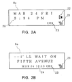
- Figs. 2A and 2B show examples of screens displayed in display window 9a of LCD 9 of this radio selective calling receiver.
- Fig. 2A is an example of the normal call-waiting state display in which the present time 20 is displayed together with graphical representations of the operation states of the device, symbol 21 showing the reception state, symbol 22 showing the notification mode, and symbol 23 showing the reception channel.
- This screen is displayed upon completion of the notification operation or display operation of a message.
- the present time is indicated as "Friday, March 24, 3:34 pm.” Obviously, if the present time is displayed in minute units, this display of the present time is updated each minute.
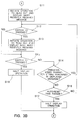
- Step S1 it is first judged whether or not a message containing the predetermined character string is stored in RAM 10. If no message containing the predetermined character string is stored, the process advances to Step S2 on the assumption of a normal call-waiting state, the current time is displayed as shown in Fig. 2A, and the process advances to Step S3. On the other hand, if a message containing the predetermined character string is stored in RAM 10 at Step S1, the message is displayed as shown in Fig. 2B at step S4 and the process advances to Step S3.
- Step S3 it is judged whether or not a message is received, the process advancing to Step S4 if a message is received, or conversely, advancing to Step S10 where it is judged whether or not switch 11 has been pressed. If it is not detected at Step S10 that switch 11 has been pressed, the process returns to Step S3, and as a result, the display state of Step S2 or Step S9 is continued as the call-waiting state as long as no message is received and switch 11 is not pressed.
- Step S5 If message reception is detected at Step S3, CPU 4 stores the received message in RAM 10 (Step S4), then initiates the notification/display operations to show that a message has been received (Step S5), and the process advances to Step S6.
- the notification/display operations are performed by the generation of an alert sound from speaker 7 and display of the received message on LCD 9.
- Step S6 it is judged whether switch 11 has been pressed or not, the process advancing to Step S8 if activation of switch 11 is detected, and if not detected, it is judged at Step S7 if the auto-reset time has passed. If the auto-reset time has not passed, the process returns to Step S6, and if the auto-reset time has passed, the process advances to Step S8.
- Step S8 the notification/display operation is halted and the process returns to Step S1.
- the notification/display operation is continued until switch 11 is pressed or the auto-reset time has elapsed, and after the notification/display operation is halted, the operation of the above-described call-waiting state is performed.
- the auto-reset time passes and the notification/display operation ends, it is likely that the user has not checked messages received up to that time, and these messages are consequently treated as unread messages and are given priority over other messages until read out by switch operation.
- These messages are also distinguished from other messages when, for example, messages are erased from the display or RAM 10.
- Step S11 If activation of switch 11 is detected in the above-described call-waiting state of Step S10, the process advances to Step S11, and the operations are initiated to read out and display on LCD 9 the messages stored in RAM 10.
- the message read out first at this time is the most recently received message.
- Step S12 which is performed while messages are being read out and displayed, judges whether separate switch 12 is pressed or not. If switch 12 is pressed, read-out and display of the next most recent message is started in Step S13 and the process advances to Step S15, and if switch 12 is not pressed, the process advances directly to Step S15. Through this operation, the displayed message can be selected.
- Step S15 it is judged if switch 11 is pressed or not, and if pressed, the process advances to Step S18 where, after halting display, the process returns to Step S1. If switch 11 is not pressed, the process advances to Step S14, and it is judged whether the currently displayed message includes the predetermined character string.
- Step S14 If a message containing the predetermined character string is being displayed in Step S14, the process returns to Step S12, and if the message does not contain the predetermined character string, the process advances to Step S16 where it is judged whether the auto-reset time has passed or not. If the auto-reset time has passed, the display operation is halted in Step S17, following which the process returns to Step S1. If the auto-reset time has not passed, the process returns to Step S12. In accordance with the above steps, display of a message lacking the predetermined character string is terminated by either activation of switch 11 or passage of the auto-reset time.
- a message containing the predetermined character string is continuously displayed until switch 11 is pressed regardless of passage of the auto-reset time, and by pressing both switch 11 and switch 12, another message can be displayed.
- a message containing the special character string is displayed during the call-waiting state despite termination of the display operation of a message by pressing switch 11.
Landscapes
- Physics & Mathematics (AREA)
- Engineering & Computer Science (AREA)
- Computer Networks & Wireless Communication (AREA)
- General Physics & Mathematics (AREA)
- Electromagnetism (AREA)
- Signal Processing (AREA)
- Mobile Radio Communication Systems (AREA)
Applications Claiming Priority (3)
| Application Number | Priority Date | Filing Date | Title |
|---|---|---|---|
| JP162901/95 | 1995-06-06 | ||
| JP16290195 | 1995-06-06 | ||
| JP7162901A JP3012487B2 (ja) | 1995-06-06 | 1995-06-06 | 伝言表示機能付き無線選択呼出受信機 |
Publications (3)
| Publication Number | Publication Date |
|---|---|
| EP0748134A2 true EP0748134A2 (fr) | 1996-12-11 |
| EP0748134A3 EP0748134A3 (fr) | 1998-03-18 |
| EP0748134B1 EP0748134B1 (fr) | 2004-10-27 |
Family
ID=15763396
Family Applications (1)
| Application Number | Title | Priority Date | Filing Date |
|---|---|---|---|
| EP96109011A Expired - Lifetime EP0748134B1 (fr) | 1995-06-06 | 1996-06-05 | Récepteur-radio d'appel sélectif à capabilité d'affichage de message |
Country Status (7)
| Country | Link |
|---|---|
| US (1) | US5774061A (fr) |
| EP (1) | EP0748134B1 (fr) |
| JP (1) | JP3012487B2 (fr) |
| KR (1) | KR100189591B1 (fr) |
| CN (1) | CN1078429C (fr) |
| DE (1) | DE69633696T2 (fr) |
| TW (1) | TW364244B (fr) |
Cited By (1)
| Publication number | Priority date | Publication date | Assignee | Title |
|---|---|---|---|---|
| EP0893790A3 (fr) * | 1997-07-24 | 2000-07-19 | Kabushiki Kaisha Toshiba | Appareil de communication radio |
Families Citing this family (12)
| Publication number | Priority date | Publication date | Assignee | Title |
|---|---|---|---|---|
| JPH09331561A (ja) * | 1996-06-12 | 1997-12-22 | Nec Shizuoka Ltd | 表示付き無線選択呼出受信機 |
| JP2786166B2 (ja) * | 1996-06-21 | 1998-08-13 | 静岡日本電気株式会社 | 無線選択呼出受信機 |
| JP2912279B2 (ja) * | 1996-12-25 | 1999-06-28 | 静岡日本電気株式会社 | 無線選択呼出受信機 |
| JPH1127371A (ja) * | 1997-07-07 | 1999-01-29 | Matsushita Electric Ind Co Ltd | 携帯電話機 |
| JP2935360B1 (ja) * | 1998-02-10 | 1999-08-16 | 日本電気株式会社 | 無線選択呼出受信機及びその制御方法 |
| JP3157774B2 (ja) * | 1998-03-27 | 2001-04-16 | 静岡日本電気株式会社 | 無線選択呼出受信機及びその表示オートリセットの制御方法 |
| JPH11331897A (ja) * | 1998-05-19 | 1999-11-30 | Nec Shizuoka Ltd | 通報保留機能付き無線選択呼出受信機および無線選択呼出受信方法 |
| US6323783B1 (en) * | 1998-09-24 | 2001-11-27 | Timex Group B.V. | Device with alternating status message display capability |
| US6996133B2 (en) | 2000-04-18 | 2006-02-07 | Zenith Electronics Corporation | Digital communication system for transmitting and receiving robustly encoded data |
| CN100435564C (zh) * | 2003-05-28 | 2008-11-19 | 松下电器产业株式会社 | 数字接口解码接收装置 |
| JP4653019B2 (ja) * | 2006-06-05 | 2011-03-16 | キヤノン株式会社 | 表示制御装置 |
| KR20160128711A (ko) | 2015-04-29 | 2016-11-08 | (주)강식품 | 유기농 수연 우동건면의 제조방법 및 이에 의해 제조된 수연 우동건면 |
Family Cites Families (18)
| Publication number | Priority date | Publication date | Assignee | Title |
|---|---|---|---|---|
| JPS58138136A (ja) * | 1982-02-12 | 1983-08-16 | Nec Corp | 表示付個別選択呼出受信機 |
| JPS61189738A (ja) * | 1985-02-18 | 1986-08-23 | Nec Corp | 不在時着信表示方式 |
| JPH0669163B2 (ja) * | 1985-09-17 | 1994-08-31 | 日本電気株式会社 | 表示機能付無線選択呼出受信機 |
| US4894649A (en) * | 1988-01-07 | 1990-01-16 | Motorola, Inc. | Pager having time controlled functions |
| JPH02151162A (ja) * | 1988-12-02 | 1990-06-11 | Nippon Telegr & Teleph Corp <Ntt> | 無線呼び出し方式 |
| GB2243507B (en) * | 1990-04-27 | 1994-07-13 | Nec Corp | Paging receiver in which an announcing unit is automatically controlled at a particular time instant |
| JPH04257127A (ja) * | 1991-02-08 | 1992-09-11 | Nec Corp | 選択呼出受信機 |
| JP2632604B2 (ja) * | 1991-03-15 | 1997-07-23 | 松下電器産業株式会社 | 選択呼出受信器 |
| WO1992017006A1 (fr) * | 1991-03-18 | 1992-10-01 | Motorola, Inc. | Recepteur d'appel selectif a presentation de message protege |
| JPH05236146A (ja) * | 1992-02-21 | 1993-09-10 | Nec Corp | 行先表示装置 |
| JPH05325080A (ja) * | 1992-05-26 | 1993-12-10 | Matsushita Electric Works Ltd | セキュリティ監視通報システム |
| JP2743718B2 (ja) * | 1992-06-30 | 1998-04-22 | 日本電気株式会社 | 表示付き無線選択呼び出し受信装置 |
| JP2778391B2 (ja) * | 1992-11-12 | 1998-07-23 | 日本電気株式会社 | 表示器付き無線選択呼出受信機 |
| KR940012897A (ko) * | 1992-11-19 | 1994-06-24 | 정용문 | 무선호출 수신기의 긴급 호 우선 표시방법 |
| JP2531074B2 (ja) * | 1993-01-28 | 1996-09-04 | 日本電気株式会社 | 無線選択呼出受信機 |
| JPH0750863A (ja) * | 1994-06-02 | 1995-02-21 | Casio Comput Co Ltd | ページング受信機 |
| US5604491A (en) * | 1995-04-24 | 1997-02-18 | Motorola, Inc. | Pager with user selectable priority |
| IT1282934B1 (it) * | 1995-11-06 | 1998-04-01 | C M A Spa | Macchina per la preparazione del caffe', cappuccino o bevande infuse simili, in dosi singole o multiple |
-
1995
- 1995-06-06 JP JP7162901A patent/JP3012487B2/ja not_active Expired - Lifetime
-
1996
- 1996-05-31 US US08/655,966 patent/US5774061A/en not_active Expired - Lifetime
- 1996-06-03 TW TW085106614A patent/TW364244B/zh active
- 1996-06-05 KR KR1019960019963A patent/KR100189591B1/ko not_active Expired - Fee Related
- 1996-06-05 EP EP96109011A patent/EP0748134B1/fr not_active Expired - Lifetime
- 1996-06-05 DE DE69633696T patent/DE69633696T2/de not_active Expired - Lifetime
- 1996-06-06 CN CN96106827A patent/CN1078429C/zh not_active Expired - Lifetime
Cited By (3)
| Publication number | Priority date | Publication date | Assignee | Title |
|---|---|---|---|---|
| EP0893790A3 (fr) * | 1997-07-24 | 2000-07-19 | Kabushiki Kaisha Toshiba | Appareil de communication radio |
| US6208878B1 (en) | 1997-07-24 | 2001-03-27 | Kabushiki Kaisha Toshiba | Radio communication apparatus |
| CN100385977C (zh) * | 1997-07-24 | 2008-04-30 | 株式会社东芝 | 无线电话装置及其显示控制方法 |
Also Published As
| Publication number | Publication date |
|---|---|
| CN1078429C (zh) | 2002-01-23 |
| EP0748134A3 (fr) | 1998-03-18 |
| KR100189591B1 (ko) | 1999-06-01 |
| TW364244B (en) | 1999-07-11 |
| KR970004418A (ko) | 1997-01-29 |
| DE69633696D1 (de) | 2004-12-02 |
| JPH08336171A (ja) | 1996-12-17 |
| EP0748134B1 (fr) | 2004-10-27 |
| CN1139867A (zh) | 1997-01-08 |
| JP3012487B2 (ja) | 2000-02-21 |
| DE69633696T2 (de) | 2005-03-17 |
| US5774061A (en) | 1998-06-30 |
Similar Documents
| Publication | Publication Date | Title |
|---|---|---|
| KR100338002B1 (ko) | 수신 메시지의 표시 방법 및 장치 | |
| US5774061A (en) | Radio selective calling receiver with message display capability | |
| KR960014493B1 (ko) | 마이크로 컴퓨터 제어된 디스플레이 백라이트 | |
| US5430440A (en) | Urgent call displaying method for a radio paging receiver | |
| CN1155266C (zh) | 通知遗失的传呼收信机的位置及其主人电话号码的方法 | |
| JP2771498B2 (ja) | メッセージ表示機能付携帯無線機 | |
| KR19980024620A (ko) | 미판독 메시지 상태를 용이하게 확인할 수 있는 무선 선택 호출수신기 | |
| US6052564A (en) | Portable individual calling device | |
| US6166621A (en) | Method and apparatus for displaying a message which has been received | |
| US6381448B2 (en) | Selective call radio receiver with mail drop message display function | |
| KR100247581B1 (ko) | 무선 선택 호출 수신기 | |
| JP2666635B2 (ja) | 表示付き個別選択呼出受信機 | |
| JP3186699B2 (ja) | 伝言表示機能付き無線選択呼出受信機 | |
| JP2890929B2 (ja) | 無線選択呼出受信機 | |
| JP2919354B2 (ja) | 個別選択呼出受信機 | |
| KR19980033376A (ko) | 선택 호출 수신기 및 선택 호출 수신기에서의 메시지 표시 방법 | |
| WO1999018552A1 (fr) | Dispositif de communication et procede de mise en oeuvre | |
| JPH04225629A (ja) | 選択呼出受信機 | |
| KR100228912B1 (ko) | 무선 호출 수신기의 연속메시지 표시 방법 | |
| KR100294046B1 (ko) | 무선호출기의미수신메시지알림방법 | |
| KR100263075B1 (ko) | 무선호출기의 메시지 상태 표시장치 및 방법 | |
| HK1031019A (en) | Communication device and method of use | |
| JPH0637702A (ja) | 無線選択呼出受信機 | |
| JPH0819019A (ja) | 受信装置 | |
| JPH04176219A (ja) | 選択呼出装置および選択呼出システムにおける受信可能時間帯の更新方法 |
Legal Events
| Date | Code | Title | Description |
|---|---|---|---|
| PUAI | Public reference made under article 153(3) epc to a published international application that has entered the european phase |
Free format text: ORIGINAL CODE: 0009012 |
|
| AK | Designated contracting states |
Kind code of ref document: A2 Designated state(s): DE GB |
|
| PUAL | Search report despatched |
Free format text: ORIGINAL CODE: 0009013 |
|
| AK | Designated contracting states |
Kind code of ref document: A3 Designated state(s): DE GB |
|
| 17P | Request for examination filed |
Effective date: 19980203 |
|
| 17Q | First examination report despatched |
Effective date: 20030228 |
|
| GRAP | Despatch of communication of intention to grant a patent |
Free format text: ORIGINAL CODE: EPIDOSNIGR1 |
|
| GRAS | Grant fee paid |
Free format text: ORIGINAL CODE: EPIDOSNIGR3 |
|
| GRAA | (expected) grant |
Free format text: ORIGINAL CODE: 0009210 |
|
| AK | Designated contracting states |
Kind code of ref document: B1 Designated state(s): DE GB |
|
| REG | Reference to a national code |
Ref country code: GB Ref legal event code: FG4D |
|
| REF | Corresponds to: |
Ref document number: 69633696 Country of ref document: DE Date of ref document: 20041202 Kind code of ref document: P |
|
| PLBE | No opposition filed within time limit |
Free format text: ORIGINAL CODE: 0009261 |
|
| STAA | Information on the status of an ep patent application or granted ep patent |
Free format text: STATUS: NO OPPOSITION FILED WITHIN TIME LIMIT |
|
| 26N | No opposition filed |
Effective date: 20050728 |
|
| PGFP | Annual fee paid to national office [announced via postgrant information from national office to epo] |
Ref country code: GB Payment date: 20150603 Year of fee payment: 20 Ref country code: DE Payment date: 20150602 Year of fee payment: 20 |
|
| REG | Reference to a national code |
Ref country code: DE Ref legal event code: R071 Ref document number: 69633696 Country of ref document: DE |
|
| REG | Reference to a national code |
Ref country code: GB Ref legal event code: PE20 Expiry date: 20160604 |
|
| PG25 | Lapsed in a contracting state [announced via postgrant information from national office to epo] |
Ref country code: GB Free format text: LAPSE BECAUSE OF EXPIRATION OF PROTECTION Effective date: 20160604 |