EP0748287B1 - Luftreifen mit verbesserter struktur der wülste und einheit von einer reifenfelge - Google Patents
Luftreifen mit verbesserter struktur der wülste und einheit von einer reifenfelge Download PDFInfo
- Publication number
- EP0748287B1 EP0748287B1 EP95909677A EP95909677A EP0748287B1 EP 0748287 B1 EP0748287 B1 EP 0748287B1 EP 95909677 A EP95909677 A EP 95909677A EP 95909677 A EP95909677 A EP 95909677A EP 0748287 B1 EP0748287 B1 EP 0748287B1
- Authority
- EP
- European Patent Office
- Prior art keywords
- bead
- axially
- rim
- outside
- seat
- Prior art date
- Legal status (The legal status is an assumption and is not a legal conclusion. Google has not performed a legal analysis and makes no representation as to the accuracy of the status listed.)
- Expired - Lifetime
Links
- 239000011324 bead Substances 0.000 title claims abstract description 144
- 230000002787 reinforcement Effects 0.000 claims abstract description 49
- 238000004804 winding Methods 0.000 claims description 10
- 230000001154 acute effect Effects 0.000 claims description 4
- 230000005484 gravity Effects 0.000 claims description 3
- 230000003014 reinforcing effect Effects 0.000 claims description 3
- 239000000203 mixture Substances 0.000 description 16
- 238000006073 displacement reaction Methods 0.000 description 3
- 230000006835 compression Effects 0.000 description 2
- 238000007906 compression Methods 0.000 description 2
- 239000002184 metal Substances 0.000 description 2
- 239000004753 textile Substances 0.000 description 2
- 239000004636 vulcanized rubber Substances 0.000 description 2
- 240000008042 Zea mays Species 0.000 description 1
- 230000000712 assembly Effects 0.000 description 1
- 238000000429 assembly Methods 0.000 description 1
- 230000009286 beneficial effect Effects 0.000 description 1
- 230000005540 biological transmission Effects 0.000 description 1
- 239000000835 fiber Substances 0.000 description 1
- 230000006870 function Effects 0.000 description 1
- 238000009434 installation Methods 0.000 description 1
- 230000004048 modification Effects 0.000 description 1
- 238000012986 modification Methods 0.000 description 1
- 230000001012 protector Effects 0.000 description 1
Images




Classifications
-
- B—PERFORMING OPERATIONS; TRANSPORTING
- B60—VEHICLES IN GENERAL
- B60C—VEHICLE TYRES; TYRE INFLATION; TYRE CHANGING; CONNECTING VALVES TO INFLATABLE ELASTIC BODIES IN GENERAL; DEVICES OR ARRANGEMENTS RELATED TO TYRES
- B60C15/00—Tyre beads, e.g. ply turn-up or overlap
- B60C15/02—Seating or securing beads on rims
- B60C15/0236—Asymmetric bead seats, e.g. different bead diameter or inclination angle
-
- B—PERFORMING OPERATIONS; TRANSPORTING
- B60—VEHICLES IN GENERAL
- B60B—VEHICLE WHEELS; CASTORS; AXLES FOR WHEELS OR CASTORS; INCREASING WHEEL ADHESION
- B60B21/00—Rims
- B60B21/10—Rims characterised by the form of tyre-seat or flange, e.g. corrugated
- B60B21/102—Rims characterised by the form of tyre-seat or flange, e.g. corrugated the shape of bead seats
-
- B—PERFORMING OPERATIONS; TRANSPORTING
- B60—VEHICLES IN GENERAL
- B60B—VEHICLE WHEELS; CASTORS; AXLES FOR WHEELS OR CASTORS; INCREASING WHEEL ADHESION
- B60B21/00—Rims
- B60B21/10—Rims characterised by the form of tyre-seat or flange, e.g. corrugated
- B60B21/104—Rims characterised by the form of tyre-seat or flange, e.g. corrugated the shape of flanges
- B60B21/106—Rims characterised by the form of tyre-seat or flange, e.g. corrugated the shape of flanges the shape of flange end-sections
-
- B—PERFORMING OPERATIONS; TRANSPORTING
- B60—VEHICLES IN GENERAL
- B60C—VEHICLE TYRES; TYRE INFLATION; TYRE CHANGING; CONNECTING VALVES TO INFLATABLE ELASTIC BODIES IN GENERAL; DEVICES OR ARRANGEMENTS RELATED TO TYRES
- B60C15/00—Tyre beads, e.g. ply turn-up or overlap
-
- B—PERFORMING OPERATIONS; TRANSPORTING
- B60—VEHICLES IN GENERAL
- B60C—VEHICLE TYRES; TYRE INFLATION; TYRE CHANGING; CONNECTING VALVES TO INFLATABLE ELASTIC BODIES IN GENERAL; DEVICES OR ARRANGEMENTS RELATED TO TYRES
- B60C15/00—Tyre beads, e.g. ply turn-up or overlap
- B60C15/0009—Tyre beads, e.g. ply turn-up or overlap features of the carcass terminal portion
- B60C15/0081—Tyre beads, e.g. ply turn-up or overlap features of the carcass terminal portion the carcass plies folded around or between more than one bead core
-
- B—PERFORMING OPERATIONS; TRANSPORTING
- B60—VEHICLES IN GENERAL
- B60C—VEHICLE TYRES; TYRE INFLATION; TYRE CHANGING; CONNECTING VALVES TO INFLATABLE ELASTIC BODIES IN GENERAL; DEVICES OR ARRANGEMENTS RELATED TO TYRES
- B60C15/00—Tyre beads, e.g. ply turn-up or overlap
- B60C15/02—Seating or securing beads on rims
-
- B—PERFORMING OPERATIONS; TRANSPORTING
- B60—VEHICLES IN GENERAL
- B60C—VEHICLE TYRES; TYRE INFLATION; TYRE CHANGING; CONNECTING VALVES TO INFLATABLE ELASTIC BODIES IN GENERAL; DEVICES OR ARRANGEMENTS RELATED TO TYRES
- B60C15/00—Tyre beads, e.g. ply turn-up or overlap
- B60C15/02—Seating or securing beads on rims
- B60C15/024—Bead contour, e.g. lips, grooves, or ribs
- B60C15/0247—Bead contour, e.g. lips, grooves, or ribs with reverse bead seat inclination, i.e. the axially inner diameter of the bead seat is bigger than the axially outer diameter thereof
-
- Y—GENERAL TAGGING OF NEW TECHNOLOGICAL DEVELOPMENTS; GENERAL TAGGING OF CROSS-SECTIONAL TECHNOLOGIES SPANNING OVER SEVERAL SECTIONS OF THE IPC; TECHNICAL SUBJECTS COVERED BY FORMER USPC CROSS-REFERENCE ART COLLECTIONS [XRACs] AND DIGESTS
- Y10—TECHNICAL SUBJECTS COVERED BY FORMER USPC
- Y10S—TECHNICAL SUBJECTS COVERED BY FORMER USPC CROSS-REFERENCE ART COLLECTIONS [XRACs] AND DIGESTS
- Y10S152/00—Resilient tires and wheels
- Y10S152/09—Bead to rim seal
-
- Y—GENERAL TAGGING OF NEW TECHNOLOGICAL DEVELOPMENTS; GENERAL TAGGING OF CROSS-SECTIONAL TECHNOLOGIES SPANNING OVER SEVERAL SECTIONS OF THE IPC; TECHNICAL SUBJECTS COVERED BY FORMER USPC CROSS-REFERENCE ART COLLECTIONS [XRACs] AND DIGESTS
- Y10—TECHNICAL SUBJECTS COVERED BY FORMER USPC
- Y10S—TECHNICAL SUBJECTS COVERED BY FORMER USPC CROSS-REFERENCE ART COLLECTIONS [XRACs] AND DIGESTS
- Y10S152/00—Resilient tires and wheels
- Y10S152/10—Split rim seal
-
- Y—GENERAL TAGGING OF NEW TECHNOLOGICAL DEVELOPMENTS; GENERAL TAGGING OF CROSS-SECTIONAL TECHNOLOGIES SPANNING OVER SEVERAL SECTIONS OF THE IPC; TECHNICAL SUBJECTS COVERED BY FORMER USPC CROSS-REFERENCE ART COLLECTIONS [XRACs] AND DIGESTS
- Y10—TECHNICAL SUBJECTS COVERED BY FORMER USPC
- Y10T—TECHNICAL SUBJECTS COVERED BY FORMER US CLASSIFICATION
- Y10T152/00—Resilient tires and wheels
- Y10T152/10—Tires, resilient
- Y10T152/10495—Pneumatic tire or inner tube
- Y10T152/10819—Characterized by the structure of the bead portion of the tire
-
- Y—GENERAL TAGGING OF NEW TECHNOLOGICAL DEVELOPMENTS; GENERAL TAGGING OF CROSS-SECTIONAL TECHNOLOGIES SPANNING OVER SEVERAL SECTIONS OF THE IPC; TECHNICAL SUBJECTS COVERED BY FORMER USPC CROSS-REFERENCE ART COLLECTIONS [XRACs] AND DIGESTS
- Y10—TECHNICAL SUBJECTS COVERED BY FORMER USPC
- Y10T—TECHNICAL SUBJECTS COVERED BY FORMER US CLASSIFICATION
- Y10T152/00—Resilient tires and wheels
- Y10T152/10—Tires, resilient
- Y10T152/10495—Pneumatic tire or inner tube
- Y10T152/10819—Characterized by the structure of the bead portion of the tire
- Y10T152/10846—Bead characterized by the chemical composition and or physical properties of elastomers or the like
-
- Y—GENERAL TAGGING OF NEW TECHNOLOGICAL DEVELOPMENTS; GENERAL TAGGING OF CROSS-SECTIONAL TECHNOLOGIES SPANNING OVER SEVERAL SECTIONS OF THE IPC; TECHNICAL SUBJECTS COVERED BY FORMER USPC CROSS-REFERENCE ART COLLECTIONS [XRACs] AND DIGESTS
- Y10—TECHNICAL SUBJECTS COVERED BY FORMER USPC
- Y10T—TECHNICAL SUBJECTS COVERED BY FORMER US CLASSIFICATION
- Y10T152/00—Resilient tires and wheels
- Y10T152/10—Tires, resilient
- Y10T152/10495—Pneumatic tire or inner tube
- Y10T152/10855—Characterized by the carcass, carcass material, or physical arrangement of the carcass materials
Definitions
- the present invention relates to a tire with a radial carcass reinforcement and more particularly the structure of the beads of said tire. It relates to also an assembly, formed of said tire and a rim, or in one piece with seats inclined or not, either in several parts, some of which are movable, and optionally provided with a support support, removable or not.
- a tire with a radial carcass reinforcement usually comprises, and known manner, a reinforcing rod in each bead, rod around which the carcass reinforcement is anchored by winding forming a reversal.
- the characteristics of said rod taken into combination with the meridian profile of the radially inner face of the bead and the meridian profile of the corresponding rim seat, provide what is called the tightening said bead on said rim.
- the tightening corresponds to a certain compression of the bead portion between the rod and the seat bead, said tightening generally being generated by a difference in angles respectively the bead seat and the rim seat and / or a difference diameters of said seats.
- the invention provides a tire of which at least one bead has a structure allowing a modification of the tightening of the bead according to the tension of the carcass reinforcement and in particular a reinforcement thereof when the inflation pressure increases to its nominal value.
- a tire with a radial carcass reinforcement, wound in each bead with at least one bead wire to form a reversal is characterized in that, mounted on a rim and inflated to its operating pressure, its carcass reinforcement, seen in meridian section, is wrapped in at least one bead around the rod coated with rubber mixture, going from the heel to the tip of said bead, the inversion extending in a profile of rubber mixture in the form of a corner delimited by two sides coming from a vertex located under the section of the coated rod, the radially external side forming, with a parallel with the axis of rotation passing through said vertex, an acute angle ⁇ 1 , open radially outwards, and the side radially internal making with said parallel an acute angle ⁇ 2 , open radially inward, the rubber mixture forming the profile, axially adjacent to the sorting ngle, having a Shore A hardness greater than the Shore A hardness (ies) of rubber mixes located
- the portion of bead, delimited simultaneously by the first wall of the bead outline and by the bead seat, is called the heel of the bead
- corner is meant a sector bounded by two sides or rays, starting from the vertex or center of the sector, straight or curvilinear, both ends respective define a third side, opposite to the center, and of form any.
- angles ⁇ 1 and ⁇ 2 made respectively by the radially outer and inner sides of the profile or corner with a parallel to the axis of rotation, are respectively between 20 ° and 70 ° and between 0 ° and 30 °.
- the rubber mixture forming the profile or wedge, axially adjacent to the rod will have a Shore A hardness at least equal to 65 (measured according to ASTM D. 67549T).
- the invention has the advantage of being able to produce, in the case of tires tourism, beads with little or no initial tightening, the face radially interior of the bead or seat being substantially dimensionally identical to the face opposite the seat of the mounting rim tire.
- the seat of the bead has in all points the same dimensions, compared to the three axes of usual coordinates, as the portion opposite the rim seat.
- the coated rod having in meridian section a section substantially circular, is advantageously likely to be rotated around its middle axis, and can be a rigid rod in torsion, such as a rod obtained by winding a wire of quadrilateral section or as a rod obtained by winding a metallic strip of right meridian section or curved, this twisted rigid coated rod is not glued to the rest of the bead.
- Another variant is to coat the rod with a thin layer of vulcanized mixture having a Shore A hardness at most equal to 35. It should be understood by mean axis of a rod the circle which is the geometrical place of the centers of gravity of the meridian sections of said rod.
- said rod can be a braided type rod, that is to say a rod formed from a core around which a wire (s) are wound, or cable (s) on one or more layers.
- a braided type rod that is to say a rod formed from a core around which a wire (s) are wound, or cable (s) on one or more layers.
- the layer (s) of wire (s) or cable (s) are likely to rotate around the core.
- the rod reinforcing the bead is surmounted radially on the outside of a substantially triangular profile in a rubber mix with preferably a Shore A hardness less than 50.
- Space, on the one hand axially adjacent to the profile radially surmounting the rod, on the other hand radially adjacent to the profile or axially corner next to the rod, is filled with a third rubbery profile substantially in shape triangular, said mixture also having a Shore hardness less than 50.
- the carcass reinforcement upturn can be substantially straight and have a length substantially equal to the length of the sides of the rubber profile as a wedge. It can be located inside said profile, part of the profile being radially above the upturn and part of the profile being below the turnaround. The latter can form the radially inner side of the rubber profile.
- the reversal will form the radially outer side of the profile or corner, it being understood that it must be accepted by convention that the reversal is also, in the two cases above, considered as extending into the profile.
- the initial tightening on the rim is zero or of a given value, that the reversal either located inside the profile or corner, on the radially outer side, or on the internal side of said profile, the axial displacement of the anchor rod of the carcass reinforcement, which can result from the tension of said reinforcement, tension due, for example, to the inflation pressure of the tire, allows, in combination with the axial arrangement of the rubber profile reinforced by the turning, obtaining a tightening of the point of the bead on the seat of rim.
- the value of this tightening increases as a function of the tension force undergone by the carcass reinforcement and can become very important in the case of tension high, for example when a sidewall of the tire is put under strong tension by a transverse force.
- the carcass reinforcement upturn will have such a length that it will be in contact with the total perimeter of the profile or corner; he will thus form the radially outer and inner sides of the rubber profile as well as the side opposite the top or center of said profile, and its end will be located axially beyond the point of intersection on both the outer and inner sides.
- the part of the reversal immediately adjacent to the part of the said reversal wrapped around the rod can first form the radially side external of the profile or corner then the side opposite the top of said profile, then finally the radially internal side of said profile to end at beyond the junction point on both the outer and inner sides.
- the end of the carcass reinforcement upturn will be radially more distant of the axis of rotation as the center of gravity of the section of the coated rod.
- the invention applies regardless of the inclination of the bead seat, but it is particularly beneficial in the case of seats tilted outwards from the pneumatic, the bead tips then being outside.
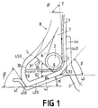
- the bead B of the passenger tire shown in FIG. 1 and in accordance with the invention, comprises a bead wire (2) of the "braided” type coated around which is wound a carcass reinforcement (1), composed, in the example shown, of a single ply of textile cables, forming a reversal (10).
- the meridian profile of the average fiber of the carcass reinforcement (1) (in dotted lines) is tangent to the rod (2) coated at a point T, and said tangent (TT ') made with a parallel to the axis of tire rotation at an angle ⁇ , open radially and axially outward, equal to 85 °.
- the contour of the bead B comprises, axially inside, a wall (440) substantially perpendicular to the axis of rotation and bearing laterally on the axially inner flange (44) of the mounting rim J.
- This rim is a rim as described in French application No. 92/15061, unpublished, that is to say having the particularity of having at least one rim seat inclined outwards, said seat being extended axially to the interior either by a rim flange or by the rim tape on which a tread support support is placed, a lateral face of said support being used as a rim flange.
- Said seat is extended axially outside by a projection or hump of low height.
- the wall (440) of the bead B is extended axially outside by a frustoconical generator (430), making with a parallel to the axis of rotation an angle ⁇ of 45 ° open axially inwards and radially towards the outside.
- Said generator (430) is itself extended axially outside by a second frustoconical generator (420) of bead seat making with the direction of the axis of rotation an angle ⁇ equal to 15 °, open axially towards the inside and radially outwards.
- Said generator is said to be inclined towards the outside, its axially outer end being on a circle with a diameter less than the diameter of the circle on which its axially inner end is located.
- the bead portion, adjacent to the wall (440) and to the generator (420), constitutes, viewed in meridian section, the heel of the bead B.
- the bead portion, adjacent to the generator (420), to the generator ( 410) and partially at the wall (450), constitutes the point of the bead B.
- the carcass reinforcement (1) is wound around the coated rod (2) going from the heel to the point of the bead B, to form a upturn (10), substantially rectilinear and which is located inside a profile (3), disposed axially outside the anchor rod (2) of the carcass reinforcement (1).
- This profile (3) is in the form of a substantially circular sector with an apex or center A located radially under the rod (2), two sides or spokes (31) and (32) starting from said apex A, and a third side (30), opposite the vertex A.
- the radially outer side or radius (31) makes with a parallel to the axis of rotation an angle ⁇ 1 equal to 45 °, while the radially inner side or radius (32) with the same parallel an angle ⁇ 2 equal to 15 °.
- This profile (3), axially completed on the outside by the substantially circular side (30), is made of a rubber mixture having in the vulcanized state a Shore A hardness equal to 94.
- the coated rod (2) is surmounted radially outside a profile (7) of rubber mixture with a Shore A hardness equal to 37. Radially outside the profile (3) and axially outside said profile (7) is disposed a third profile ( 6) in a rubbery mixture having a Shore A hardness equal to that of the profile (7) and therefore significantly less than the hardness of the mixture of the profile (3), which allows, when the carcass reinforcement is increased in tension , to facilitate the axial displacement of the braided rod (2) towards the outside of the bead B and thus to create a compression of the profile (3) and a self-tightening of the bead tip on the mounting rim J, while , in the case described, the initial tightening of the bead J on the adite rim sucks.
- the bead B is completed by the protector (5).
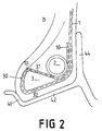
- Figure 2 shows the variant of a bead according to the invention, this variant characterized by the fact that the inversion (10) of the carcass reinforcement (1) completely surrounds the contour of the profile (3), firstly forming the side radially inside (32) of the profile (3), secondly the lateral side (30) axially exterior of said profile then lastly the radially exterior side (31) of the same profile, to wind again around the rod (2), the end of said reversal being radially situated above the rod (2). Said end is thus advantageously removed from deformations usually to which the ends of carcass reinforcement upturns, deformations resulting in poor endurance resistance of the beads.
- the assembly formed by a tire according to the invention and a rim, can include a rim with two rim seats identical to each other and whose axially inner ends are on circles of diameters greater than diameters of the circles on which the ends lie axially exterior, such seats being shown in Figures 1 and 2.
- the assembly tire-rim may, according to another variant, comprise a rim having on the one hand a first seat as defined above and said inclined outwards and on the other hand a second seat said inclined inwards, the end axially interior of said seat being on a circle of diameter less than the diameter of the circle on which the axially outer end is located.
- the tire of said assembly obviously comprises beads of a shape adapted to the shape of the rim seats.
- the tire-rim assembly may also include a rim whose two seats (42) are inclined inwards, the axially internal end of each seat (42) being on a circle with a diameter less than the diameter of the circle on which finds the axially outer end, said seats (42) being joined axially to the outside with two flanges (44).
- FIG. 3 shows a bead B, according to a third variant in accordance with the invention, suitable for being mounted on a rim seat (42), inclined inwards and joined axially on the outside to a rim flange (44 ).
- the heel of the bead B is then located axially outside while the tip of said bead is axially inside, the rim flange (s) (44) then being located axially outside the rim J.
- the center of the meridian section of the coated rod (2) is located in the axially outer part of the bead B, or if L is called the width of the bead B, said center O is separated from the inner wall of the rim flange (44) at a distance at most equal to half of L.
- the radially outer side (31) makes an angle ⁇ 1 equal to 30 ° with a parallel to the axis of rotation, while the radially inner side (32) makes an angle ⁇ 2 equal to 5 ° with the same parallel.
- the profile (3) is made, as before, of vulcanized rubber mixture having a Shore A hardness equal to 94.
- the rubber mixture profiles (6) and (7) which, respectively, are arranged radially outside the profile (3) and radially outside the rod (2) are similar to the profiles (6) and (7) described in the description part referring to Figures 1 and 2.
- the meridian profile of the reversal d carcass reinforcement is however different from the profiles described above; in fact, the upturn (10) of the carcass reinforcement (1) completely surrounds the contour of the profile (3), firstly forming the radially outer side (31) of the profile (3), secondly the lateral side ( 30) axially outside of said profile then lastly the radially inner side (32) of the same profile, to wind again around the rod (2), the end of said reversal being always radially situated above the rod (2) .
- FIG. 4 shows an assembly formed by a tire conforming to the invention, mounted on its service rim.
- Said rim J is a one-piece rim having rim seats (42), inclined with respect to the direction of the axis of rotation of the assembly inward and making with said direction an equal angle at 15 ° ⁇ 1 °, curved rim flanges (44) axially outside said seats and a mounting groove, according to the standards in force.
- the reversal (10) of the carcass reinforcement (1) surrounds, going from the heel to the point of the bead, the profile (3) in its entirety, the end of the upturn (10) being radially above the rod metallic (2).
- the reversal (10) forms firstly the radially inner side (32) of the profile (3), secondly the lateral side (30) axially inside said profile then lastly the side radially outside (31) of the same profile, to wrap around again of the rod (2), this turning profile making it possible to have the end of said turning axially inside the meridian profile of the carcass reinforcement and thus improve the fatigue endurance of beads.
- Said endurance can to be further improved by the presence between the carcass reinforcement and its inversion of an additional reinforcement armature (9), formed of cables, textile or metallic, oriented with respect to the circumferential direction of a small angle, which can be between 0 ° and 45 °.
- the tire-rim assembly can advantageously comprise a rim J having on the one hand a first seat (42 '), as defined above, and said inclined towards the outside and on the other hand a second seat (42 '') said inclined towards the inside, the tire of said assembly obviously comprising beads of shape adapted to the shape of the rim seats (42 ') and (42' ').
- the two seats can then have equal diameters or unequal diameters.
- the rim J which forms with a tire, in accordance with the invention, the assembly shown in FIG. 5, is a rim as, for example, described in the unpublished French application 93/14703, and more precisely in the passage of the description of said request relating to Figure 3 of the accompanying drawing.
- the rim J comprises a first rim seat (42 '), the axially outer end of which is on a circle with a diameter less than the diameter of the circle on which the axially inner end is located, and a second rim seat (42'') whose axially outer end is on a circle of diameter greater than the diameter on which the axially inner end is located.
- the two seats (42 ') and (42'') have frustoconical generators making an angle with the axis of rotation, identical for the two generators and equal to 6 °.
- the first seat (42 ') is extended axially outside by a projection or hump (41') of low height h 0 , equal to 3.5 mm and having a frustoconical inner wall forming with the axis of rotation of the rim an angle ⁇ ', equal to 45 °.
- the first rim seat (42 ') is joined to a rim tape (40), by means of a frustoconical generator, the diameter D N of said cylindrical rim tape being slightly greater than the diameter D ' B of the axially inner end of the seat (42'), diameter itself greater than the diameter D ' S of the outer projection (41').
- the second rim seat (42 '') is extended axially on the outside by a rim flange (44), having an inner wall perpendicular to the axis of rotation and having a radially outer end whose diameter D R is the maximum rim diameter.
- the second rim seat (42 '') is extended by a protuberance (41 ''), whose height h 1 is similar to the height of the projections or humps normally used on current and standardized rims.
- the two rim seats (42 ') and (42''), asymmetrical by the directions of inclination of their generatrices, are also so by their diameters, the diameter D'' B of the axially inner end of the second seat of rim (42 '') being greater than the diameter D ' B of the axially inner end of the first rim seat (42').
- the assembly is completed by a tread support support S, maintained in the axial position, on the one hand by one of the beads B of the tire mounted on its rim J and on the other hand by a protuberance (45) disposed on the rim tape (40), the lateral face of the support bearing being considered to be the equivalent of the wall of a rim flange axially inside the rim seat.
- the beads B of the tire are then adapted to such a rim configuration: in the bead (B) intended to be mounted on the first rim seat (42 '), the carcass reinforcement (1) is wound around the bead coated (2 '), in accordance with the invention, going axially from the inside to the outside since, in this bead, the bead is inside, the wall of the rim flange being advantageously replaced by the equivalent wall support support S; in the bead (B) intended to be mounted on the second rim seat (42 ''), the carcass reinforcement (1) is wound around the coated rod (2 '') from the outside to the inside since the heel of said bead is then axially outside.
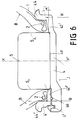
- FIG. 6 is shown another example of an assembly composed of a tire according to the invention, a rim J and a support support S.
- Said rim J comprises three metal parts: a first part (4 ) mainly consisting of the rim tape (40) joined, on one side to a first rim seat (42 ') and axially on the outside to a rim flange (44') integral with the seat (42 '), and comprising on the other side the part intended to receive the second metal part (4 ') of the rim J.
- Said removable part (4') consists of a rim seat (42 '') and a flange of rim (44 '').
- the third piece is the locking ring (4 '').
- the rim seats (42 ') and (42'') respectively have generators symmetrical with respect to the equatorial plane of the assembly, and frustoconical by making with the direction of the axis of rotation an angle ⁇ ' open radially and axially outward equal to 5 °.
- the two rim flanges (44 ') and (44'') being axially outside the two rim seats (42') and (42 ''), the carcass reinforcement (1), in each bead B , wraps around the rod (2) from the outside to the inside and then returns under the rod (2), after having surrounded, as in the examples already described, a profile (3) of rubber mixture as a wedge.
- the assembly is advantageously completed in this example by a support support S whose meridian section is substantially rectangular and whose radially inner face rests on the cylindrical face of the rim tape (40).
- the lateral sides S 1 and S 2 axially distant from the maximum axial width of the support S, are in contact with the axially inner walls of the tips of the beads B, and thus avoid the axial displacement of the beads B of the tire towards the interior in the case of running at low or zero pressure.
- the example shown in Figure 7 differs from that in Figure 6 by the following features: the seal is removed, the rim seat (42 '') is no longer part of the moving part located on the side, for example, outside of the assembly, the generator of said seat (42 '') having become parallel to the axis of rotation and said seat (42 '') can then be an integral part of the rim tape (40), the rim flange (44 '') remaining mobile only.
- the rim has become asymmetrical in that its rim seat (42 ') has a frustoconical generator and that its rim seat (42 '') has a generator parallel to the axis of rotation.
- the seat rim (42 ''), always an integral part of the rim tape (40) has a generator formed of a frustoconical portion axially inside and over at least 75% of the axial width of the seat, including the angle ⁇ '', with the direction parallel to the axis of rotation, is equal to 5 ° but open radially outwards and axially towards inside, said frustoconical portion being extended axially outside by a cylindrical generator.
- the rim seat (42 ') retains a frustoconical generator making with the direction parallel to the axis of rotation an angle ⁇ 'equal to 5 ° and open radially and axially outward.
- the carcass reinforcement (1) is wound in each bead B around the rod (2) going from the heel to the toe of said bead, then surround in its entirety the rubber mix profile (3) arranged axially inside the rod (2).
Landscapes
- Engineering & Computer Science (AREA)
- Mechanical Engineering (AREA)
- Tires In General (AREA)
- Friction Gearing (AREA)
- Tyre Moulding (AREA)
- Compositions Of Macromolecular Compounds (AREA)
- Laminated Bodies (AREA)
Claims (25)
- Reifen mit radialer Karkassenbewehrung (1), die in jedem Wulst B mit mindestens einem Wulstkern (2) herumgewickelt ist, um einen Umschlag (10) zu bilden, wobei die radial innenliegende Fläche des genannten Wulstes im wesentlichen der Dimension nach identisch mit der Fläche des Sitzes der Montagefelge J ist,
dadurch gekennzeichnet, daß,
wenn er auf seiner Felge montiert ist und auf seinen Betriebsdruck aufgepumpt ist, seine Karkassenbewehrung (1), im Meridianschnitt gesehen, in mindestens einem Wulst B rund um den Wulstkern (2) herumgewickelt ist, der mit einer gummiartigen Mischung umhüllt ist, wobei man von der Flanke bis zur Spitze des genannten Wulstes B fortschreitet, wobei sich der Umschlag (10) in einem Profil (3) aus gummiartiger Mischung in Form eines Keiles erstreckt, der durch zwei Seiten (31) und (32) begrenzt ist, die von einem Scheitel A ausgehen, der unter dem Querschnitt des umhüllten Wulstkernes (2) angeordnet ist, wobei die radial außenliegende Seite (31) mit einer Parallele zur Drehachse, die durch den genannten Scheitel A hindurchläuft, einen spitzen Winkel 1, bildet, der radial nach außen offen ist, und die radial innenliegende Seite (32) zur genannten Parallelen einen spitzen Winkel 2 bildet, der radial nach innen offen ist, und wobei die kautschukartige Mischung, die das Profil (3) axial neben dem Wulstkern bildet, eine Shorehärte A aufweist, die größer ist als die Shorehärte(n) A der gummiartigen Mischungen axial und radial über dem Wulstkern (2) und dem Profil (3). - Reifen nach Anspruch 1, dadurch gekennzeichnet, daß der Winkel 1, zwischen 20° und 70° liegt, und dann der Winkel 2 zwischen 0° und 30° liegt.
- Reifen nach einem der Ansprüche 1 oder 2, dadurch gekennzeichnet, daß die gummiartige Mischung, die das Profil (3) axial neben dem Wulstkern bildet, eine Shorehärte A aufweist, die mindestens 65 beträgt.
- Reifen nach einem der Ansprüche 1 bis 3, dadurch gekennzeichnet, daß radial an der Außenseite über dem Wulstkern (2), der den Wulst B verstärkt, ein im wesentlichen dreieckiges Profil (7) aus gummiartiger Mischung angebracht ist, das eine Shorehärte A aufweist, die kleiner als 50 ist, wobei der Raum einerseits axial neben dem Profil (7) und andererseits radial neben dem Profil (3) axial an der Seite des Wulstkerns (2) von einem dritten Profil (6) aus gummiartiger Mischung ausgefüllt ist, das im wesentlichen dreieckig ist, wobei die genannte Mischung ebenfalls eine Shorehärte kleiner als 50 aufweist.
- Reifen nach einem der Ansprüche 1 bis 4, dadurch gekennzeichnet, daß der umhüllte Wulstkern (2), der im Meridianschnitt einen im wesentlichen kreisförmigen Querschnitt aufweist, vorteilhafterweise imstande ist, zu einer Drehung um seine Mittelachse angeregt zu werden.
- Reifen nach Anspruch 5, dadurch gekennzeichnet, daß der umhüllte Wulstkern (2) ein torsionssteifer Wulstkern ist, der mit einer dünnen Lage aus kautschukartiger, vulkanisierter Mischung umhüllt ist, die eine Shorehärte A aufweist, die höchstens 35 beträgt.
- Reifen nach Anspruch 5, dadurch gekennzeichnet, daß der umhüllte Wulstkern (2) der Art nach ein "geflochtener" Wulstkern ist, d.h. ein Wulstkern, der von einer Seele gebildet ist, um welche ein Draht bzw. Drähte oder Seil bzw. Seile in einer oder mehreren Lagen herumgewickelt ist bzw. sind.
- Reifen nach einem der Ansprüche 1 bis 7, dadurch gekennzeichnet, daß der Umschlag (10) der Karkassenbewehrung (1) im wesentlichen geradlinig ist, eine Länge aufweist, die im wesentlichen gleich ist der Länge der Seiten (31) und (32) des Gummiprofils (3), und die radial innenliegende Seite (32) des Gummiprofils (3) bildet.
- Reifen nach einem der Ansprüche 1 bis 7, dadurch gekennzeichnet, daß der Umschlag (10) der Karkassenbewehrung (1) im wesentlichen geradlinig ist, eine Länge aufweist, die im wesentlichen gleich ist der Länge der Seiten (31) und (32) des Gummiprofils (3), und die radial außenliegende Seite (32) des Profils (3) bildet.
- Reifen nach einem der Ansprüche 1 bis 7, dadurch gekennzeichnet, daß der Umschlag (10) der Karkassenbewehrung (1) eine solche Länge aufweist, daß er in Berührung mit dem gesamten Umfang des Profils (3) steht und somit die beiden Seiten bildet, nämlich die radial außenliegende und innenliegende (31) und (32), des Gummiprofils (3), sowie die Seite (30), die dem Scheitel A oder der Mitte des genannten Profils (3) gegenüberliegt, wobei das Ende des genannten Umschlags (10) axial jenseits des Schnittpunkts A der beiden Seiten, nämlich der Außenseite und Innenseite (31) und (32), liegt.
- Reifen nach Anspruch 10, dadurch gekennzeichnet, daß das Ende des Umschlags (10) der Karkassenbewehrung (1) radial weiter von der Drehachse entfernt ist als der Schwerpunkt des Querschnitt des umhüllten Wulstkerns (2).
- Reifen nach einem der Ansprüche 1 bis 11, dadurch gekennzeichnet, daß er mindestens einen ersten Wulst B aufweist, dessen Sitz nach außen geneigt ist, wobei die Flanke des Wulstes axial auf der Innenseite liegt, während die Spitze des Wulstes axial auf der Außenseite liegt, und die Karkassenbewehrung (1) sich um den Wulstkern (2) herumwickelt, indem sie von der Innenseite zur Außenseite verläuft.
- Reifen nach einem der Ansprüche 1 bis 11, dadurch gekennzeichnet, daß er mindestens einen ersten Wulst B aufweist, dessen Sitz nach innen geneigt ist, wobei die Flanke des Wulstes axial auf der Außenseite liegt, während die Spitze des Wulstes axial auf der Innenseite liegt, und die Karkassenbewehrung (1) sich um den Wulstkern (2) herumwickelt, wobei sie von der Außenseite zur Innenseite verläuft.
- Reifen nach einem der Ansprüche 1 bis 11, dadurch gekennzeichnet, daß er mindestens einen ersten Wulst B aufweist, dessen Sitz eine zur Drehachse parallele Erzeugende aufweist, wobei die Flanke des Wulstes axial auf der Außenseite liegt und die Spitze des Wulstes axial auf der Innenseite liegt, und die Karkassenbewehrung (1) sich um den Wulstkern (2) herumwickelt, während sie von der Außenseite zur Innenseite verläuft.
- Reifen nach einem der Ansprüche 1 bis 11, dadurch gekennzeichnet, daß er mindestens einen ersten Wulst B aufweist, dessen Sitz nach außen über mindestens 75 % seiner axialen Breite geneigt ist, wobei die Flanke des Wulstes axial auf der Außenseite liegt, während die Spitze des Wulstes axial auf der Innenseite liegt, und die Karkassenbewehrung (1) sich um den Wulstkern (2) herumwickelt, während sie von der Außenseite zur Innensetiet verläuft.
- Reifen nach Anspruch 12, dadurch gekennzeichnet, daß er einen zweiten Wulst B aufweist, der in Bezug auf die Äquatorialebene des Reifens zum ersten Wulst symmetrisch ist.
- Reifen nach Anspruch 12, dadurch gekennzeichnet, daß er einen zweiten Wulst B aufweist, dessen Sitz nach innen geneigt ist, wobei die Flanke des Wulstes axial auf der Außenseite liegt, während die Spitze des Wulstes axial auf der Innenseite liegt, und die Karkassenbewehrung (1) sich um den Wulstkern (2) herumwickelt, während sie von der Außenseite zur Innenseite verläuft.
- Reifen nach Anspruch 13, dadurch gekennzeichnet, daß er einen zweiten Wulst B aufweist, der in Bezug auf die Äquatorialebene des Reifens zum ersten Wulst symmetrisch ist.
- Reifen nach Anspruch 13, dadurch gekennzeichnet, daß er einen zweiten Wulst B aufweist, dessen Sitz eine zur Drehachse parallele Erzeugende aufweist, wobei die Flanke dieses zweiten Wulstes sich axial an der Außenseite befindet und die Spitze des Wulstes sich axial an der Innenseite befindet, und die Karkassenbewehrung (1) sich um den Wulstkern (2) herumwickelt, während sie von der Außenseite zur Innenseite verläuft.
- Reifen nach Anspruch 13, dadurch gekennzeichnet, daß er einen zweiten Wulst B aufweist, dessen Sitz nach außen geneigt ist, wobei die Flanke dieses zweiten Wulstes sich axial an der Außenseite befindet, während die Spitze des Wulstes sich axial an der Innenseite befindet, und die Karkassenbewehrung (1) sich um den Wulstkern (2) herumwickelt, während sie von der Außenseite zur Innenseite verläuft.
- Baugruppe, die aus einem Reifen nach Anspruch 16 gebildet ist, mit einer Felge J, die einen ersten, nach außen geneigten Felgensitz (42) aufweist, wobei der genannte Sitz axial zur Innenseite um einen Felgenring (44) und axial zur Außenseite um einen Vorsprung oder Höcker (41) mit geringer Höhe verlängert ist, und einen zweiten, nach außen geneigten Felgensitz (42), wobei der genannte zweite Sitz axial durch einen Felgenboden (40) verlängert ist, auf dem eine Stützauflage für die Lauffläche aufgesetzt ist, von der eine Seite als Felgenring benutzt ist, und axial zur Außenseite durch einen Vorsprung oder Höcker (41).
- Baugruppe, die aus einem Reifen nach Anspruch 17 gebildet ist, mit einer Felge J, die einen ersten, nach außen geneigten Felgensitz (42') aufweist, wobei die genannte Felge axial auf der Innenseite durch einen Felgenboden (40) verlängert ist, auf den eine Stützauflage S für die Lauffläche aufgelegt ist, deren eine Seitenfläche als Felgenring benutzt ist, und axial auf der Außenseite durch einen Vorsprung oder Höcker (41'), und mit einem zweiten Felgensitz (42''), der nach innen geneigt ist, wobei der genannte zweite Felgensitz axial zur Außenseite um einen Felgenring (44) und axial auf der Innenseite durch einen Vorsprung oder Höcker (41'') mit geringer Höhe verlängert ist.
- Baugruppe, die aus einem Reifen nach Anspruch 18 gebildet ist, mit einer Felge J, die aus drei Teilen gebildet ist, von denen mindestens zwei abnehmbar sind und zwei Felgensitze (42', 42'') aufweisen, die nach innen geneigt sind, sowie eine Stützauflage S für die Lauffläche, deren axiale Breite im wesentlichen gleich ist dem axialen Abstand, der die beiden Wülste B des Reifens trennt.
- Baugruppe, die aus einem Reifen nach Anspruch 19 gebildet ist, mit einer Felge J, die aus drei Teilen zusammengesetzt ist, von denen mindestens zwei abnehmbar sind, mit einem ersten Felgensitz (42'), der nach innen geneigt ist, wobei der genannte Sitz axial nach außen um einen Felgenring (44') verlängert ist, und einem zweiten Felgensitz (42''), dessen Erzeugende eine Paralle zur Drehachse ist, wobei der genannte zweite Felgensitz axial durch einen zweiten Felgenring (44'') verlängert ist, und mit einer Stützauflage S für die Lauffläche, deren axiale Breite im wesentlichen gleich ist dem axialen Abstand, der die beiden Wülste B des Reifens trennt.
- Baugruppe, die aus einem Reifen nach Anspruch 20 gebildet ist, mit einer Felge J, die aus drei Teilen zusammengesetzt ist, von denen mindestens zwei abnehmbar sind, mit einem ersten Felgensitz (42'), der nach innen geneigt ist, wobei der genannte Sitz axial zur Außenseite um einen Felgenring (44') verlängert ist, und einem zweiten Felgensitz (42''), der nach außen über mindestens 75 % seiner axialen Breite geneigt ist, wobei der genannte zweite Felgensitz axial nach außen um einen Felgenring (44'') verlängert ist, und mit einer Stützauflage S für die Lauffläche, deren axiale Breite im wesentlichen gleich ist dem axialen Abstand, der die beiden Wülste B des Reifens trennt.
Applications Claiming Priority (3)
| Application Number | Priority Date | Filing Date | Title |
|---|---|---|---|
| FR9402371A FR2716645B1 (fr) | 1994-02-28 | 1994-02-28 | Pneumatique avec des bourrelets de structure améliorée et ensemble d'un tel pneumatique avec une jante adaptée. |
| FR9402371 | 1994-02-28 | ||
| PCT/EP1995/000426 WO1995023073A1 (fr) | 1994-02-28 | 1995-02-07 | Pneumatique avec des bourrelets de structure amelioree et ensemble d'un tel pneumatique avec une jante adaptee |
Publications (2)
| Publication Number | Publication Date |
|---|---|
| EP0748287A1 EP0748287A1 (de) | 1996-12-18 |
| EP0748287B1 true EP0748287B1 (de) | 1998-11-11 |
Family
ID=9460571
Family Applications (1)
| Application Number | Title | Priority Date | Filing Date |
|---|---|---|---|
| EP95909677A Expired - Lifetime EP0748287B1 (de) | 1994-02-28 | 1995-02-07 | Luftreifen mit verbesserter struktur der wülste und einheit von einer reifenfelge |
Country Status (17)
| Country | Link |
|---|---|
| US (3) | US5971047A (de) |
| EP (1) | EP0748287B1 (de) |
| JP (1) | JP3724805B2 (de) |
| KR (1) | KR100322644B1 (de) |
| CN (1) | CN1052197C (de) |
| AT (1) | ATE173205T1 (de) |
| AU (1) | AU678703B2 (de) |
| BR (1) | BR9506875A (de) |
| CA (1) | CA2183681C (de) |
| DE (1) | DE69505954T2 (de) |
| DK (1) | DK0748287T3 (de) |
| ES (1) | ES2125601T3 (de) |
| FR (1) | FR2716645B1 (de) |
| MX (1) | MX9602562A (de) |
| PL (1) | PL175709B1 (de) |
| RU (1) | RU2133676C1 (de) |
| WO (1) | WO1995023073A1 (de) |
Cited By (5)
| Publication number | Priority date | Publication date | Assignee | Title |
|---|---|---|---|---|
| WO2001040000A1 (fr) * | 1999-12-03 | 2001-06-07 | Societe De Technologie Michelin | Bourrelet pour pneumatique a mobilite etendue |
| US6378585B1 (en) | 1998-12-21 | 2002-04-30 | Bridgestone Corporation | Heavy duty pneumatic tire and method of manufacturing the same |
| EP1318029A1 (de) * | 2001-11-27 | 2003-06-11 | Société de Technologie Michelin | Reifen mit multiplen Karkassenlagen und Reifenwülsten mit einer speziellen Struktur |
| WO2006069896A1 (fr) * | 2004-12-24 | 2006-07-06 | Societe De Technologie Michelin | Bourrelet de pneumatique facilitant le montage et methode de construction d'un tel bourrelet |
| WO2007009596A1 (fr) * | 2005-07-19 | 2007-01-25 | Societe De Technologie Michelin | Pneumatique a mobilite etendue avec flanc souple |
Families Citing this family (41)
| Publication number | Priority date | Publication date | Assignee | Title |
|---|---|---|---|---|
| FR2716645B1 (fr) * | 1994-02-28 | 1996-04-19 | Michelin & Cie | Pneumatique avec des bourrelets de structure améliorée et ensemble d'un tel pneumatique avec une jante adaptée. |
| US6408919B2 (en) | 1998-04-27 | 2002-06-25 | Compagnie Generale Des Etablissements, Michelin-Michelin & Cie | Method and apparatus for manufacturing tires |
| FR2779386B1 (fr) | 1998-06-05 | 2000-06-30 | Michelin & Cie | Pneumatique a protuberance de flanc et/ou de bourrelet striee |
| PT1084027E (pt) | 1998-06-05 | 2003-06-30 | Pirelli | Processo para o fabrico de um pneu para rodas de veiculos pneu esse que pode ser obtido atraves do referido processo e uma roda de veiculo compreendendo o referido pneu |
| US6506274B1 (en) * | 1998-07-23 | 2003-01-14 | Michelin Recherche Et Technique, S.A. | Apparatus and method for manufacture of tires |
| US20030041975A1 (en) * | 1998-07-23 | 2003-03-06 | Michelin Recherche Et Technique, S.A. | Apparatus and method for manufacture of tires |
| FR2788238B1 (fr) | 1999-01-13 | 2001-02-16 | Michelin Soc Tech | Pneumatique avec des bourrelets de structure amelioree |
| FR2788239B1 (fr) * | 1999-01-13 | 2001-02-16 | Michelin Soc Tech | Pneumatique avec des bourrelets de structure amelioree |
| WO2001025031A1 (en) * | 1999-09-30 | 2001-04-12 | The Goodyear Tire & Rubber Company | Pneumatic tyre having locked beads |
| KR20020060246A (ko) * | 1999-12-03 | 2002-07-16 | 미첼 롤리에르 | 확장된 이동성을 가진 타이어 비드 |
| FR2804906B1 (fr) | 2000-02-10 | 2002-09-20 | Michelin Soc Tech | Bourrelet de pneumatique |
| FR2807971A1 (fr) * | 2000-04-25 | 2001-10-26 | Michelin Soc Tech | Bourrelet allege de pneumatique radial |
| WO2001089861A1 (fr) | 2000-05-22 | 2001-11-29 | Societe De Technologie Michelin | Pneumatique comprenant un profile de renfort dans au moins un flanc, et ensemble monte pneumatique/jante |
| FR2810924B1 (fr) * | 2000-07-03 | 2003-04-11 | Michelin Soc Tech | Pneumatique avec des bourrelets de structure amelioree |
| JP2002192921A (ja) * | 2000-11-20 | 2002-07-10 | Goodyear Tire & Rubber Co:The | らせん六角ビードおよび製造方法 |
| DE60117695T2 (de) * | 2000-12-22 | 2006-11-09 | Pirelli Pneumatici S.P.A. | Selbststützender reifen für fahrzeugsräder und verfahren zur herstellung desselben |
| FR2819450B1 (fr) * | 2001-01-17 | 2003-09-05 | Michelin Soc Tech | Pneumatique avec au moins un bourrelet a siege incline vers l'exterieur et un flanc avec anneau additionnel |
| US20030150538A1 (en) * | 2001-02-28 | 2003-08-14 | Renato Ceretta | Tyre for a vehicle wheels with self support-functions, and a rim for said tyre |
| KR100393476B1 (ko) * | 2001-03-20 | 2003-08-02 | 금호산업주식회사 | 비드부를 보강한 공기입 타이어 |
| KR100405124B1 (ko) * | 2001-03-20 | 2003-12-01 | 금호타이어 주식회사 | 비드부를 보강한 공기입 타이어 |
| KR100392424B1 (ko) * | 2001-03-20 | 2003-07-23 | 금호산업주식회사 | 비드부를 보강한 공기입 타이어 |
| KR20050054977A (ko) * | 2002-10-14 | 2005-06-10 | 소시에떼 드 테크놀로지 미쉐린 | 대칭 힘으로 분산된 비드를 포함하는 연장 이동성 타이어 |
| ATE370848T1 (de) * | 2002-10-16 | 2007-09-15 | Michelin Soc Tech | Reifenwulstschutz |
| DE60320669T2 (de) * | 2002-11-04 | 2009-06-10 | Société de Technologie Michelin | Langzeitreifen mit ausgerücktem verankerungsbereich |
| DE60318746T2 (de) * | 2002-12-30 | 2009-01-15 | Société de Technologie Michelin | Montageverfahren zum aufbau eines reifens |
| DE10327678A1 (de) * | 2003-06-20 | 2005-01-05 | Continental Aktiengesellschaft | Fahrzeugluftreifen |
| JP4616261B2 (ja) * | 2003-09-18 | 2011-01-19 | ソシエテ ド テクノロジー ミシュラン | 非対称に配置されたビード付きの延長移動性タイヤ |
| JP3808858B2 (ja) | 2003-10-07 | 2006-08-16 | 住友ゴム工業株式会社 | サポートリング、及びタイヤ組立体 |
| US7448422B2 (en) * | 2004-04-22 | 2008-11-11 | The Goodyear Tire & Rubber Company | Pneumatic run-flat tire |
| US7406991B2 (en) * | 2004-12-22 | 2008-08-05 | The Goodyear Tire & Rubber Company | Pneumatic tire with bead composite |
| US7004218B1 (en) | 2004-12-22 | 2006-02-28 | The Goodyear Tire & Rubber Company | Pneumatic tire with specified carcass ply turn-up |
| FR2879966B1 (fr) * | 2004-12-24 | 2009-03-06 | Michelin Soc Tech | Pneumatique et jante dont au moins un siege comporte une nervure |
| US7509987B2 (en) * | 2005-11-22 | 2009-03-31 | The Goodyear Tire & Rubber Company | Tire with turned down ply construction |
| US7971615B2 (en) * | 2005-11-22 | 2011-07-05 | The Goodyear Tire & Rubber Company | Tire with turned down ply construction |
| US7670449B2 (en) * | 2005-11-22 | 2010-03-02 | The Goodyear Tire & Rubber Company | Method of manufacturing tire with turned down ply construction |
| ATE452774T1 (de) * | 2007-06-01 | 2010-01-15 | Michelin Soc Tech | Verfahren zum verhindern des schlupfes eines reifens auf einer reifen-/radanordnung und danach hergestellte reifen-/radanordnung |
| FR2919220B1 (fr) * | 2007-07-23 | 2012-08-03 | Michelin Soc Tech | Procede de fabrication d'un pneumatique asymetrique. |
| US20090038731A1 (en) | 2007-08-06 | 2009-02-12 | Robert Allen Losey | Pneumatic Run-Flat Tire |
| US8627866B2 (en) * | 2009-01-09 | 2014-01-14 | Bridgestone Americas Tire Operations, Llc | Tire and wheel rim assembly |
| JP5886057B2 (ja) * | 2012-01-17 | 2016-03-16 | 東洋ゴム工業株式会社 | 空気入りタイヤ |
| RU2701603C1 (ru) * | 2019-03-29 | 2019-09-30 | Артур Армович Каспаров | Колесо транспортного средства |
Family Cites Families (13)
| Publication number | Priority date | Publication date | Assignee | Title |
|---|---|---|---|---|
| US903714A (en) * | 1908-04-11 | 1908-11-10 | Charles Gilbert Hawley | Pneumatic-tire casing. |
| US1261754A (en) * | 1914-01-26 | 1918-04-09 | Erle K Baker | Pneumatic tire. |
| US1919911A (en) * | 1930-09-17 | 1933-07-25 | Alvin H Shoemaker | Pneumatic tire and rim construction |
| GB767378A (en) * | 1954-03-11 | 1957-01-30 | Pirelli | Improvements relating to pneumatic vehicle wheel tyres |
| US2868258A (en) * | 1956-12-14 | 1959-01-13 | Firestone Tire & Rubber Co | Tubeless tire and rim therefor |
| FR1327810A (fr) * | 1962-04-09 | 1963-05-24 | Fr Du Pneu Englebert Soc | Talon perfectionné de pneumatique |
| NL129169C (de) * | 1963-05-04 | Michelin & Cie | ||
| AR196280A1 (es) * | 1972-12-20 | 1973-12-10 | Pirelli | Neumatico para rueda de vehiculos |
| LU71465A1 (de) * | 1974-12-10 | 1975-06-11 | ||
| EP0077161A3 (de) * | 1981-10-09 | 1984-03-21 | Dunlop Limited | Luftreifen |
| SU1641653A1 (ru) * | 1987-11-05 | 1991-04-15 | Научно-исследовательский институт крупногабаритных шин | Колесо транспортного средства |
| FR2713557B1 (fr) * | 1993-12-08 | 1996-03-01 | Michelin & Cie | Jante, anneau de soutien et ensemble comprenant lesdits éléments. |
| FR2716645B1 (fr) * | 1994-02-28 | 1996-04-19 | Michelin & Cie | Pneumatique avec des bourrelets de structure améliorée et ensemble d'un tel pneumatique avec une jante adaptée. |
-
1994
- 1994-02-28 FR FR9402371A patent/FR2716645B1/fr not_active Expired - Fee Related
-
1995
- 1995-02-07 KR KR1019960704715A patent/KR100322644B1/ko not_active Expired - Fee Related
- 1995-02-07 ES ES95909677T patent/ES2125601T3/es not_active Expired - Lifetime
- 1995-02-07 DE DE69505954T patent/DE69505954T2/de not_active Expired - Lifetime
- 1995-02-07 CN CN95191111A patent/CN1052197C/zh not_active Expired - Fee Related
- 1995-02-07 BR BR9506875A patent/BR9506875A/pt not_active IP Right Cessation
- 1995-02-07 WO PCT/EP1995/000426 patent/WO1995023073A1/fr not_active Ceased
- 1995-02-07 JP JP52209495A patent/JP3724805B2/ja not_active Expired - Fee Related
- 1995-02-07 DK DK95909677T patent/DK0748287T3/da active
- 1995-02-07 CA CA002183681A patent/CA2183681C/fr not_active Expired - Fee Related
- 1995-02-07 AU AU18487/95A patent/AU678703B2/en not_active Ceased
- 1995-02-07 RU RU96119954/28A patent/RU2133676C1/ru not_active IP Right Cessation
- 1995-02-07 US US08/682,548 patent/US5971047A/en not_active Expired - Lifetime
- 1995-02-07 AT AT95909677T patent/ATE173205T1/de not_active IP Right Cessation
- 1995-02-07 PL PL95316036A patent/PL175709B1/pl not_active IP Right Cessation
- 1995-02-07 MX MX9602562A patent/MX9602562A/es not_active IP Right Cessation
- 1995-02-07 EP EP95909677A patent/EP0748287B1/de not_active Expired - Lifetime
-
1999
- 1999-01-28 US US09/239,168 patent/US6179028B1/en not_active Expired - Fee Related
-
2000
- 2000-11-17 US US09/715,804 patent/US6626220B1/en not_active Expired - Fee Related
Cited By (8)
| Publication number | Priority date | Publication date | Assignee | Title |
|---|---|---|---|---|
| US6378585B1 (en) | 1998-12-21 | 2002-04-30 | Bridgestone Corporation | Heavy duty pneumatic tire and method of manufacturing the same |
| WO2001040000A1 (fr) * | 1999-12-03 | 2001-06-07 | Societe De Technologie Michelin | Bourrelet pour pneumatique a mobilite etendue |
| EP1318029A1 (de) * | 2001-11-27 | 2003-06-11 | Société de Technologie Michelin | Reifen mit multiplen Karkassenlagen und Reifenwülsten mit einer speziellen Struktur |
| EP1526004A1 (de) * | 2001-11-27 | 2005-04-27 | Société de Technologie Michelin | Reifen mit multiplen Karkassenlagen und Reifenwülsten mit einer speziellen Struktur |
| WO2006069896A1 (fr) * | 2004-12-24 | 2006-07-06 | Societe De Technologie Michelin | Bourrelet de pneumatique facilitant le montage et methode de construction d'un tel bourrelet |
| CN100537277C (zh) * | 2004-12-24 | 2009-09-09 | 米其林技术公司 | 便于安装的胎圈和制造这样胎圈的方法 |
| WO2007009596A1 (fr) * | 2005-07-19 | 2007-01-25 | Societe De Technologie Michelin | Pneumatique a mobilite etendue avec flanc souple |
| FR2888777A1 (fr) * | 2005-07-19 | 2007-01-26 | Michelin Soc Tech | Pneumatique a mobilite etendue avec flanc souple |
Also Published As
| Publication number | Publication date |
|---|---|
| JPH09509122A (ja) | 1997-09-16 |
| FR2716645A1 (fr) | 1995-09-01 |
| PL316036A1 (en) | 1996-12-23 |
| DK0748287T3 (da) | 1999-07-26 |
| JP3724805B2 (ja) | 2005-12-07 |
| PL175709B1 (pl) | 1999-01-29 |
| DE69505954D1 (de) | 1998-12-17 |
| MX9602562A (es) | 1997-03-29 |
| RU2133676C1 (ru) | 1999-07-27 |
| CA2183681C (fr) | 2005-11-15 |
| BR9506875A (pt) | 1997-09-09 |
| CN1052197C (zh) | 2000-05-10 |
| EP0748287A1 (de) | 1996-12-18 |
| WO1995023073A1 (fr) | 1995-08-31 |
| CN1137777A (zh) | 1996-12-11 |
| AU1848795A (en) | 1995-09-11 |
| CA2183681A1 (fr) | 1995-08-31 |
| US6179028B1 (en) | 2001-01-30 |
| DE69505954T2 (de) | 1999-05-12 |
| ES2125601T3 (es) | 1999-03-01 |
| AU678703B2 (en) | 1997-06-05 |
| ATE173205T1 (de) | 1998-11-15 |
| US5971047A (en) | 1999-10-26 |
| US6626220B1 (en) | 2003-09-30 |
| FR2716645B1 (fr) | 1996-04-19 |
| KR970701127A (ko) | 1997-03-17 |
| KR100322644B1 (ko) | 2002-06-24 |
Similar Documents
| Publication | Publication Date | Title |
|---|---|---|
| EP0748287B1 (de) | Luftreifen mit verbesserter struktur der wülste und einheit von einer reifenfelge | |
| EP0673324B1 (de) | Luftreifen, felge, notlaufring und einheit bestehend aus denselben | |
| EP0733000B1 (de) | Reifen, felge, stützring und einrichtung mit diesen teilen | |
| EP0518098B1 (de) | Flachbettfelge für schlauchlose Lastkraftwagenreifen, Einheit dieser Felge mit Reifen, dessen Höhe-zu-Breiteverhältnis kleiner dann 0,80 ist | |
| CA2334098A1 (fr) | Bourrelet renforce de pneumatique radial | |
| EP0168754B1 (de) | Gürtelreifen mit zwei Wulstkernen per Wulst | |
| CA2359325C (fr) | Pneumatique avec des bourrelets de structure amelioree | |
| EP1289779B1 (de) | Reifen mit einem verstärkungselement in mindestens einer seitenwand und montierte reifen/felge einheit | |
| EP1307351B1 (de) | Reifen mit verbesserter wulststruktur | |
| EP1353811B1 (de) | Fahrzeugluftreifen mit einem konzentrisch zum reifen angerordneten ring | |
| WO2001058705A1 (fr) | Bourrelet de pneumatique | |
| EP0498214B1 (de) | Einheit Felge-Reifen, die eine Entwulstung vermeidet | |
| EP0835769B9 (de) | Stützvorrichtung für eine Reifenlauffläche | |
| EP1261498B1 (de) | Felge mit nach aussen geneigten schultern und anordnung mit einer derartigen felge und aufgeblasener unterstützvorrichtung | |
| FR2610872A1 (fr) | Roue de vehicule a caracteristiques de securite de fonctionnement en cas d'avarie | |
| FR2809348A1 (fr) | Pneumatique comprenant un profile de renfort dans au moins un flanc et ensemble pneumatique/jante comprenant un tel pneumatique | |
| EP1838540B1 (de) | Reifen, von dem mindestens ein wulstsitz eine rippe umfasst | |
| WO2007088169A1 (fr) | Pneumatique avec des sièges de diamètres inégaux et à déport axial inversé à l'état gonflé | |
| FR2809054A1 (fr) | Pneumatique, ensemble pneumatique et jante | |
| WO2005095125A1 (fr) | Structure de renforcement de bourrelet de pneumatique. |
Legal Events
| Date | Code | Title | Description |
|---|---|---|---|
| PUAI | Public reference made under article 153(3) epc to a published international application that has entered the european phase |
Free format text: ORIGINAL CODE: 0009012 |
|
| 17P | Request for examination filed |
Effective date: 19960930 |
|
| AK | Designated contracting states |
Kind code of ref document: A1 Designated state(s): AT BE CH DE DK ES FR GB IT LI LU NL SE |
|
| GRAG | Despatch of communication of intention to grant |
Free format text: ORIGINAL CODE: EPIDOS AGRA |
|
| 17Q | First examination report despatched |
Effective date: 19980122 |
|
| GRAG | Despatch of communication of intention to grant |
Free format text: ORIGINAL CODE: EPIDOS AGRA |
|
| GRAH | Despatch of communication of intention to grant a patent |
Free format text: ORIGINAL CODE: EPIDOS IGRA |
|
| GRAH | Despatch of communication of intention to grant a patent |
Free format text: ORIGINAL CODE: EPIDOS IGRA |
|
| GRAA | (expected) grant |
Free format text: ORIGINAL CODE: 0009210 |
|
| AK | Designated contracting states |
Kind code of ref document: B1 Designated state(s): AT BE CH DE DK ES FR GB IT LI LU NL SE |
|
| REF | Corresponds to: |
Ref document number: 173205 Country of ref document: AT Date of ref document: 19981115 Kind code of ref document: T |
|
| REG | Reference to a national code |
Ref country code: CH Ref legal event code: EP |
|
| REG | Reference to a national code |
Ref country code: CH Ref legal event code: NV Representative=s name: MICHELIN RECHERCHE ET TECHNIQUE S.A. |
|
| REF | Corresponds to: |
Ref document number: 69505954 Country of ref document: DE Date of ref document: 19981217 |
|
| GBT | Gb: translation of ep patent filed (gb section 77(6)(a)/1977) |
Effective date: 19990127 |
|
| REG | Reference to a national code |
Ref country code: ES Ref legal event code: FG2A Ref document number: 2125601 Country of ref document: ES Kind code of ref document: T3 |
|
| REG | Reference to a national code |
Ref country code: DK Ref legal event code: T3 |
|
| PLBE | No opposition filed within time limit |
Free format text: ORIGINAL CODE: 0009261 |
|
| STAA | Information on the status of an ep patent application or granted ep patent |
Free format text: STATUS: NO OPPOSITION FILED WITHIN TIME LIMIT |
|
| 26N | No opposition filed | ||
| REG | Reference to a national code |
Ref country code: GB Ref legal event code: IF02 |
|
| PGFP | Annual fee paid to national office [announced via postgrant information from national office to epo] |
Ref country code: ES Payment date: 20080228 Year of fee payment: 14 Ref country code: DK Payment date: 20080215 Year of fee payment: 14 Ref country code: CH Payment date: 20080215 Year of fee payment: 14 |
|
| PGFP | Annual fee paid to national office [announced via postgrant information from national office to epo] |
Ref country code: SE Payment date: 20080214 Year of fee payment: 14 Ref country code: NL Payment date: 20080214 Year of fee payment: 14 Ref country code: LU Payment date: 20080225 Year of fee payment: 14 Ref country code: GB Payment date: 20080220 Year of fee payment: 14 |
|
| PGFP | Annual fee paid to national office [announced via postgrant information from national office to epo] |
Ref country code: AT Payment date: 20080215 Year of fee payment: 14 |
|
| PGFP | Annual fee paid to national office [announced via postgrant information from national office to epo] |
Ref country code: BE Payment date: 20080327 Year of fee payment: 14 |
|
| BERE | Be: lapsed |
Owner name: CIE GENERALE DES ETS *MICHELIN - MICHELIN & CIE Effective date: 20090228 |
|
| PGFP | Annual fee paid to national office [announced via postgrant information from national office to epo] |
Ref country code: IT Payment date: 20090221 Year of fee payment: 15 |
|
| REG | Reference to a national code |
Ref country code: CH Ref legal event code: PL |
|
| EUG | Se: european patent has lapsed | ||
| REG | Reference to a national code |
Ref country code: DK Ref legal event code: EBP |
|
| GBPC | Gb: european patent ceased through non-payment of renewal fee |
Effective date: 20090207 |
|
| PG25 | Lapsed in a contracting state [announced via postgrant information from national office to epo] |
Ref country code: LI Free format text: LAPSE BECAUSE OF NON-PAYMENT OF DUE FEES Effective date: 20090228 Ref country code: CH Free format text: LAPSE BECAUSE OF NON-PAYMENT OF DUE FEES Effective date: 20090228 Ref country code: AT Free format text: LAPSE BECAUSE OF NON-PAYMENT OF DUE FEES Effective date: 20090207 |
|
| PGFP | Annual fee paid to national office [announced via postgrant information from national office to epo] |
Ref country code: FR Payment date: 20090213 Year of fee payment: 15 |
|
| NLV4 | Nl: lapsed or anulled due to non-payment of the annual fee |
Effective date: 20090901 |
|
| PG25 | Lapsed in a contracting state [announced via postgrant information from national office to epo] |
Ref country code: NL Free format text: LAPSE BECAUSE OF NON-PAYMENT OF DUE FEES Effective date: 20090901 |
|
| PG25 | Lapsed in a contracting state [announced via postgrant information from national office to epo] |
Ref country code: BE Free format text: LAPSE BECAUSE OF NON-PAYMENT OF DUE FEES Effective date: 20090228 |
|
| REG | Reference to a national code |
Ref country code: ES Ref legal event code: FD2A Effective date: 20090209 |
|
| PG25 | Lapsed in a contracting state [announced via postgrant information from national office to epo] |
Ref country code: GB Free format text: LAPSE BECAUSE OF NON-PAYMENT OF DUE FEES Effective date: 20090207 |
|
| PG25 | Lapsed in a contracting state [announced via postgrant information from national office to epo] |
Ref country code: ES Free format text: LAPSE BECAUSE OF NON-PAYMENT OF DUE FEES Effective date: 20090209 Ref country code: DK Free format text: LAPSE BECAUSE OF NON-PAYMENT OF DUE FEES Effective date: 20090831 |
|
| REG | Reference to a national code |
Ref country code: FR Ref legal event code: ST Effective date: 20101029 |
|
| PG25 | Lapsed in a contracting state [announced via postgrant information from national office to epo] |
Ref country code: FR Free format text: LAPSE BECAUSE OF NON-PAYMENT OF DUE FEES Effective date: 20100301 |
|
| PG25 | Lapsed in a contracting state [announced via postgrant information from national office to epo] |
Ref country code: IT Free format text: LAPSE BECAUSE OF NON-PAYMENT OF DUE FEES Effective date: 20100207 |
|
| PG25 | Lapsed in a contracting state [announced via postgrant information from national office to epo] |
Ref country code: LU Free format text: LAPSE BECAUSE OF NON-PAYMENT OF DUE FEES Effective date: 20090207 |
|
| PG25 | Lapsed in a contracting state [announced via postgrant information from national office to epo] |
Ref country code: SE Free format text: LAPSE BECAUSE OF NON-PAYMENT OF DUE FEES Effective date: 20090208 |
|
| PGFP | Annual fee paid to national office [announced via postgrant information from national office to epo] |
Ref country code: DE Payment date: 20110218 Year of fee payment: 17 |
|
| REG | Reference to a national code |
Ref country code: DE Ref legal event code: R119 Ref document number: 69505954 Country of ref document: DE Effective date: 20120901 |
|
| PG25 | Lapsed in a contracting state [announced via postgrant information from national office to epo] |
Ref country code: DE Free format text: LAPSE BECAUSE OF NON-PAYMENT OF DUE FEES Effective date: 20120901 |