EP0748551B1 - Lutte contre le brouillage des signaux en transmission numerique - Google Patents
Lutte contre le brouillage des signaux en transmission numerique Download PDFInfo
- Publication number
- EP0748551B1 EP0748551B1 EP95938574A EP95938574A EP0748551B1 EP 0748551 B1 EP0748551 B1 EP 0748551B1 EP 95938574 A EP95938574 A EP 95938574A EP 95938574 A EP95938574 A EP 95938574A EP 0748551 B1 EP0748551 B1 EP 0748551B1
- Authority
- EP
- European Patent Office
- Prior art keywords
- signal
- filter
- taps
- interference
- feedback
- Prior art date
- Legal status (The legal status is an assumption and is not a legal conclusion. Google has not performed a legal analysis and makes no representation as to the accuracy of the status listed.)
- Expired - Lifetime
Links
- 230000005540 biological transmission Effects 0.000 title description 12
- 230000003044 adaptive effect Effects 0.000 claims description 68
- 238000001914 filtration Methods 0.000 claims description 31
- 238000000034 method Methods 0.000 claims description 24
- 230000003111 delayed effect Effects 0.000 claims description 6
- 230000001419 dependent effect Effects 0.000 claims description 3
- 230000001934 delay Effects 0.000 claims description 2
- 238000001228 spectrum Methods 0.000 description 12
- 239000000969 carrier Substances 0.000 description 10
- 238000010586 diagram Methods 0.000 description 9
- 230000004044 response Effects 0.000 description 9
- 230000000737 periodic effect Effects 0.000 description 5
- 230000005039 memory span Effects 0.000 description 4
- 238000012360 testing method Methods 0.000 description 4
- 239000000654 additive Substances 0.000 description 3
- 230000000996 additive effect Effects 0.000 description 3
- 238000013459 approach Methods 0.000 description 3
- 230000036961 partial effect Effects 0.000 description 3
- 230000006978 adaptation Effects 0.000 description 2
- 238000004891 communication Methods 0.000 description 2
- 230000000875 corresponding effect Effects 0.000 description 2
- 238000012545 processing Methods 0.000 description 2
- 230000002238 attenuated effect Effects 0.000 description 1
- 230000015556 catabolic process Effects 0.000 description 1
- 238000004040 coloring Methods 0.000 description 1
- 238000010276 construction Methods 0.000 description 1
- 230000002596 correlated effect Effects 0.000 description 1
- 230000005574 cross-species transmission Effects 0.000 description 1
- 238000013144 data compression Methods 0.000 description 1
- 230000003247 decreasing effect Effects 0.000 description 1
- 238000006731 degradation reaction Methods 0.000 description 1
- 238000013461 design Methods 0.000 description 1
- 238000002592 echocardiography Methods 0.000 description 1
- 230000000694 effects Effects 0.000 description 1
- 238000005516 engineering process Methods 0.000 description 1
- 230000002452 interceptive effect Effects 0.000 description 1
- 230000000670 limiting effect Effects 0.000 description 1
- 230000002829 reductive effect Effects 0.000 description 1
- 238000004088 simulation Methods 0.000 description 1
- 230000001360 synchronised effect Effects 0.000 description 1
- 238000012549 training Methods 0.000 description 1
Images

Classifications
-
- H—ELECTRICITY
- H04—ELECTRIC COMMUNICATION TECHNIQUE
- H04L—TRANSMISSION OF DIGITAL INFORMATION, e.g. TELEGRAPHIC COMMUNICATION
- H04L25/00—Baseband systems
- H04L25/02—Details ; arrangements for supplying electrical power along data transmission lines
- H04L25/03—Shaping networks in transmitter or receiver, e.g. adaptive shaping networks
- H04L25/03006—Arrangements for removing intersymbol interference
- H04L25/03012—Arrangements for removing intersymbol interference operating in the time domain
- H04L25/03019—Arrangements for removing intersymbol interference operating in the time domain adaptive, i.e. capable of adjustment during data reception
- H04L25/03057—Arrangements for removing intersymbol interference operating in the time domain adaptive, i.e. capable of adjustment during data reception with a recursive structure
-
- H—ELECTRICITY
- H04—ELECTRIC COMMUNICATION TECHNIQUE
- H04N—PICTORIAL COMMUNICATION, e.g. TELEVISION
- H04N5/00—Details of television systems
- H04N5/14—Picture signal circuitry for video frequency region
- H04N5/21—Circuitry for suppressing or minimising disturbance, e.g. moiré or halo
-
- H—ELECTRICITY
- H04—ELECTRIC COMMUNICATION TECHNIQUE
- H04N—PICTORIAL COMMUNICATION, e.g. TELEVISION
- H04N7/00—Television systems
- H04N7/10—Adaptations for transmission by electrical cable
- H04N7/102—Circuits therefor, e.g. noise reducers, equalisers, amplifiers
-
- H—ELECTRICITY
- H04—ELECTRIC COMMUNICATION TECHNIQUE
- H04B—TRANSMISSION
- H04B1/00—Details of transmission systems, not covered by a single one of groups H04B3/00 - H04B13/00; Details of transmission systems not characterised by the medium used for transmission
- H04B1/06—Receivers
- H04B1/10—Means associated with receiver for limiting or suppressing noise or interference
- H04B1/12—Neutralising, balancing, or compensation arrangements
- H04B1/123—Neutralising, balancing, or compensation arrangements using adaptive balancing or compensation means
-
- H—ELECTRICITY
- H04—ELECTRIC COMMUNICATION TECHNIQUE
- H04N—PICTORIAL COMMUNICATION, e.g. TELEVISION
- H04N21/00—Selective content distribution, e.g. interactive television or video on demand [VOD]
- H04N21/40—Client devices specifically adapted for the reception of or interaction with content, e.g. set-top-box [STB]; Operations thereof
- H04N21/41—Structure of client; Structure of client peripherals
- H04N21/426—Internal components of the client ; Characteristics thereof
Definitions
- the present invention is directed generally to digital signal processing, and in particular to receiver based methods and devices for combating signal interference in digital HDTV transmission.
- the FCC plans to test and approve an advanced television (ATV) standard comprising for example, high definition television (HDTV) and standard definition television (SDTV) digital signals for terrestrial broadcasting.
- ATV advanced television
- HDTV high definition television
- SDTV standard definition television
- Fig. 1 shows two geographical areas A and B.
- Transmission antenna 1 in area A transmits NTSC channel 6.
- the FCC will not permit antenna 2 in area B to also transmit NTSC channel 6, as the proximity of antenna 2 to antenna 1 could cause NTSC interference in both areas.
- area A is transmitting NTSC channel 6, then channel 6 in area B is a so-called "taboo" channel.
- the FCC will now permit antenna 2 in area B to transmit ATV signals on channel 6 as the new ATV signals are much more resistant to NTSC interference, although NTSC interference will still be a problem especially in the fringe area 3.
- NTSC will be used hereinafter to represent one example of conventional television broadcasting. Other examples would be, inter alia, SECAM and PAL. Although NTSC is exemplified herein, it is not meant to be construed as a limitation and will be used herein synonymously with conventional" to represent conventional television in general.
- the FCC intends to test the so-called "Grand Alliance" digital ATV system, a system which is being cooperatively developed by the corporate sponsors which developed the first round of individual proposals which were tested by the FCC in 1991 and 1992.
- the Grand Alliance has already decided on a coding algorithm which will comply with the source coding standards proposed by MPEG (Motion Pictures Experts Group).
- MPEG Motion Pictures Experts Group
- the RF transmission scheme selected on the basis of testing conducted by the Advanced Television Test Center (ATTC) is the trellis coded 8VSB system designed and built by Zenith Electronics.
- the system details are described in "Digital Spectrum Compatible - Technical Details", September 23, 1991 and more recently modified for bakeoff and described in "VSB Transmission System: Technical Details", September 19, 1994.
- This system is also described in an article in Broadcast Engineering by Chan, entitled “A Look at 8-VSB", September 1994 at page 10, and in TV Technology in an article by Weiss, entitled “And the Winner is VSB.. Maybe", April 1994 at page 50.
- Fig. 2 shows an example of the frequency spectrum of an NTSC signal.
- the carriers of the picture V, sound A and color C of the NTSC signal will cause interference with the digital HDTV signal.
- the Zenith 8VSB modem uses a comb filter in the receiver having a response 4 which introduces nulls, in the digital spectrum at the locations of the carriers of the picture V, sound A and color C as shown.
- the NTSC rejection filter (comb filter), shown in Fig. 3, provides rejection of steady-state signals located at the null frequencies.
- the ATV spectrum In order to ensure that the nulls align with the correct carrier frequency, the ATV spectrum must be shifted 45.8kHz with respect to the NTSC spectrum, as described at page 15 of "VSB Transmission System: Technical Details", and also delayed by 12 symbols, as described below.
- the comb filter of Fig. 3 comprises a 12 symbol delay 8 which receives the input signal of the comb filter, and a subtracter 9 to subtract the output of the delay 8 from the input signal of the comb filter.
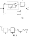
- Fig. 4 shows the prior art use of the comb filter in the Zenith system.
- Trellis decoding with and without NTSC rejection filter (comb filter) is illustrated.
- Received symbols r k are applied to a first branch 20 comprising a comb-filter 8, 9 which applies 15 level symbols + noise + interference to a partial response trellis decoder 11, and to a second branch 10 in which 8 level symbols + noise + interference are applied to an optimal trellis decoder 12.
- a switch 13 supplies output data from the first branch 10 or the second branch 20.
- the comb filter 8, 9 is switched into use when NTSC interference is present in the digital signal, otherwise the comb filter 8, 9 is not used. This provides significant improvement in the performance of the digital signal when a conventional television signal, e.g. NTSC, is broadcast on a co-channel.
- a general description of a comb filter can be found in Pohlmann "Principles of Digital Audio", 2nd ed. 1991.
- the comb filter 8, 9 in the prior art is treated as a partial response channel in cascade with a trellis coder, for the case when co-channel conventional television interference is present.
- An optimum partial response trellis decoder 11 can then be developed which uses Viterbi decoding on an expanded trellis, the states of which correspond to the cascade of the states of the comb-filter and the trellis coder as described in "Principles of Digital Communication and Coding" by Andrew J. Viterbi and Jim K. Omura, 1979, specifically at pages 227-300.
- the number of states in the trellis becomes increasingly large as the number of delays in the comb filter increase. Accordingly, the trellis coded 8VSB system, which uses a comb filter 8, 9 with a delay 8 of 12 symbols, has an extremely large number of trellis states and also suffers from the problems associated with additive noise.
- Zenith converts the MPEG coded and RS coded and interleaved data-stream from serial to parallel, then uses twelve parallel trellis encoders followed by a parallel to serial converter at the transmitter.
- the trellis decoder 11 for the case when the comb filter 8, 9 is used, implements Viterbi decoding on a trellis with the number of states equal to two or four times the number of states of the trellis encoder.
- the problems associated with additive noise still occur and in fact cause the trellis decoder to work improperly.
- the comb filter 8,9 When the co-channel conventional television interference is absent, the comb filter 8,9 is not switched into use and the Viterbi decoding is implemented by means of an optimal trellis decoder 12 on a trellis with the number of states equal to the number of states of the trellis encoder. This is possible since, with the Zenith approach, pre-coding is not used in the transmitter.
- the choice between the path 10, afforded by simple trellis decoding 12, or of the path 20, which employs the comb filter 8, 9 and the expanded trellis 12 at the receiver, is decided by the measured error-rate of the periodically sent data field sync symbols at the outputs of the post comb and with no post comb.
- the comb filter path 20 will be chosen which increases the number of states of the trellis decoder.
- the switching between the use of a comb filter 8, 9 in the receiver or not, suggested by Zenith, is cumbersome.
- a significant number of computations must be performed to determine whether the comb filter should be used or not.
- the use of the comb filter requires 12 parallel encoders and correspondingly 12 parallel decoders which is also very cumbersome.
- a problem similar to co-channel interference occurs when a digital signal is transmitted thru cable in a new channel next to existing analog channels.
- Intermodulation products are one of the most important distortion types on cable, so that maximum number of channels that can be put on cable is most times limited by the occurrence of intermodulation products.
- the non-intermodulation-product-disturbed channels of which are already fully occupied by existing (analog) channels the new channel for the digital signal will be subject to intermodulation product interference.
- Another source of disturbing signal interference may be caused by a single carrier signal. Put more generally, the problem to be solved is caused by signal interference.
- EP 0 277 393-A1 discloses an arrangement for combatting intersymbol interference and noise introduced into a data signal transmitted at a symbol rate 1/T by a transmission channel having a memory span LT corresponding to a number of L consecutive data symbols, comprising a receive filter (RF), a first decision circuit (ID) for forming preliminary symbol decisions in response to the transmitted data signal, a second decision circuit (FD) for forming final symbol decisions, means (FFS and FBS) for compensating pre-and post-cursive intersymbol interference, and a combining circuit (AD) for forming the input signal for the second decision circuit (FD).
- RF receive filter
- ID first decision circuit
- FD second decision circuit
- FBS means
- AD combining circuit
- the invention provides methods of removing interference from a digital signal, filtering systems for the same purpose, and a television receiver as defined in the independent claims.
- the dependent claims define advantageous embodiments.
- Embodiments of the invention provide an adaptive filter which can dynamically adapt itself to the NTSC spectrum and hence pick out the NTSC interference which is then removed from a received digital signal without the need for a comb filter.
- the received input signal r is delayed and then applied to an adaptive filter.
- the output of the adaptive filter is subtracted from the received signal r.
- the result of this subtraction, "the error” is used to adjust the taps of the adaptive filter.
- the adaptive filter becomes tuned to the carriers of the NTSC signal.
- the NTSC signal is then subtracted from the received signal r leaving only the unpredictable components ("the error") of the received signal.
- This "error" includes the digital signal and the AWGN and can now be easily processed by simple trellis decoding without the need for a comb filter.
- the adaptive filter is provided with filter taps which are automatically adjustable for tuning into the periodic components of the NTSC signal without having to use the NTSC signal as a reference signal.
- the adaptive filter is a feedforward filter.
- the invention incorporates a decision feedback equalizer (DFE) using a finite impulse response filter in the feedback path for combatting intersymbol interference.
- DFE decision feedback equalizer
- a forward filter is also provided which removes the pre-echo or ghosts in the received signals. If a DFE is used without any adaptive filter and there is strong NTSC interference in the received signal the taps of the feedback filter become very large which causes an increase in error propagation in the DFE, decreasing the DFE's expected performance of cancelling out the multipaths.
- the DFE will try to cancel the signal from the adaptive filter as the DFE believes the signal from the adaptive filter is a multipath which again causes an increase in error propagation.
- a DFE can only cancel multipaths up to the number of taps in the feedback filter.
- This is achieved by setting the delay D of the adaptive filter such that it is greater than the number of taps in the feedback filter. In this way the DFE will not attempt to cancel the "multipath" it sees from the adaptive filter, thus the DFE effectively removes ghosts yet error propagation of the DFE is not increased and the NTSC signals are removed by the adaptive filter.
- the NTSC signal estimate ⁇ k is subtracted from the output of the forward filter.
- the output of the feedback filter is also subtracted from the output of the forward filter.
- a slicer is provided for quantizing the signal to the nearest symbol. The subtractor compares the input of the slicer to the output of the slicer and provides an error signal e' k which is used to set the taps of the forward filter and the feedback filter by using an adaptive algorithm.
- the DFE at all times, is trying to minimize the error e' k .
- Another object of this invention is to avoid the use of the comb filter in the receiver to remove NTSC interference transmitted on a co-channel from a digital signal.
- Yet a further object of the invention is to improve the AWGN performance of the trellis encoder/decoder in an ATV receiver when co-channel television interference is not present. This is achieved by not having to use a comb filter which limits the number of states of the trellis encoder due to the fact the Viterbi decoder on a comb filter path must operate on a trellis with at least double the number of states of the trellis encoder.
- Yet another object of the invention is to do away with the 45.8kHz frequency offset required with the use of a comb filter.
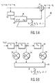
- Fig. 5A generally indicates at 40 the basic structure of an adaptive filter for signal interference cancellation ("the filter 40"). While in the following, NTSC co-channel interference is mentioned as an example, the filter 40 is able to remove other interference signals, such as intermodulation product interference.
- the filter 40 includes a delay element 42, an adaptive filter circuit 43 with adjustable taps g 1 ... g Lg , and a subtractor circuit 41.
- the input to filter 40 is the sequence r k which includes the transmitted symbol sequence a k of a digital signal, the NTSC co-channel interference i k and the AWGN n k .
- the output of the adaptive filter 40 is e k , which is the "error" signal formed by subtracting ⁇ k , which is an estimate of i k , from r k .
- This "error" signal e k therefore includes the digital signal a k plus the AWGN n k .
- the filter 40 is provided for "tuning" to the carriers or periodic components of the NTSC co-channel interference i k which carriers are then estimated and subtracted in subtraction circuit 41 from the received signal r k .
- the output of subtractor circuit 41 is the non-periodic components of the received signal r k , which is the original digital signal a k plus the additive AWGN n k .
- the output e k is then sent to a trellis decoder which is adapted to easily remove the AWGN n k .
- the filter 40 is able to remove the NTSC co-channel interference because the received signal r k is first passed through a delay element 42 having a delay of D symbols. This delay is chosen sufficiently large so as to decorrelate the broadband component of r k which is a k + n k .
- a reference signal such as the actual NTSC signal being transmitted on the co-channel which is used to generate an error which error is then minimized by tuning the filter taps by the LMS algorithm. In the present case such a reference signal is not needed, and usually not available.
- the delay D is chosen of sufficient length to decorrelate the broad band noise, the actual NTSC signal transmitted on the co-channel is not needed.
- the NTSC component because of the periodic nature of its carriers, will remain correlated. The predictable NTSC component is removed from the received signal leaving only the unpredictable component a k + n k at the output.
- D When there is no multipath, D can be set to 1 since both the signal and noise components are white. The situation with multipath will be discussed later.
- D is the adaptive filter circuit 43 with adjustable taps [g 1 , g 2 , ...,g 1g ], which are shown more clearly in Fig. 5B.
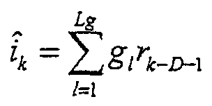
- the output of the adaptive filter circuit 43, denoted by ⁇ k is given by:
- the filter taps [g 1 , g 2 , ...,g 1g ] are then obtained by minimizing the mean squared error E[e k 2] with respect to the taps.
- the theoretical expression for the optimum taps involves exact knowledge of the correlation properties of the NTSC interference which are obviously not available to the receiver.
- an adaptive algorithm is used to update the taps in the adaptive filter circuit 43 which minimizes the mean squared error.
- other adaptive algorithms besides the LMS algorithm may be used to adjust the taps.
- the adaptive filter becomes matched to the NTSC spectrum "blindly" i.e. no reference NTSC co-channel signal or reference data stream is required for adaptation.
- Fig. 5B is a more detailed diagram of the adaptive filter 43.
- a plurality of delay line segments D 1 , D 2 ...D Lg form a tapped delay line.
- Each of the delay line segments D 1 , D 2 ... D Lg are coupled at points 30, 31...32 to a respective multiplier 33, 34,..35 having respective tap coefficients g 1 , g 2 ...g Lg .
- Outputs of the multiplexer 33, 34, ... 35 are applied to a summer 36.
- an adaptive algorithm must be used to adjust the value of the multiplier taps g 1 , g 2 ...g Lg .
- the adjustable multiplier taps g 1 , g 2 ...g Lg to minimize the mean squared error as explained above, it can be shown that the minimum of the mean squared error will occur when the adjustable multiplier taps g 1 , g 2 ...g Lg are tuned to the carriers of the NTSC co-channel interference. That is, when the frequency response of the adaptive filter 43 defined by the adjustable multiplier taps g 1 , g 2 ...g Lg matches the frequency response of the NTSC co-channel interference the mean squared error will be minimized.
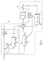
- Fig. 6 shows a second embodiment of this invention which includes a DFE 50 and the filter 40.
- the DFE includes a forward filter 55, a feedback filter 51, a slicer 52, and subtractors 53 and 54.
- the DFE 50 removes multipaths such as pre-echoes or ghosts. If the DFE 50 is subject to NTSC interference the taps of the feedback filter 51 become quite large which increases error propagation. That is, if an error is made in determining the symbol â k at the output of slicer 52, this incorrect symbol is fed back to the input of the filter 51 and into future tap coefficients of the forward filter 55 and the feedback filter 51.
- the DFE 50 will treat the estimated NTSC co-channel interference ⁇ k , received from filter 40, as a multipath and attempt to cancel it, which is not wanted. Because the number of multipaths the DFE 50 can cancel is related to the number of taps in the feedback filter 51, that is the DFE 50 can only cancel at most Lb multipaths, by setting the delay D equal to Lb the DFE will not attempt to cancel this multipath. Thus, the error propagation through the DFE is reduced.
- the embodiment shown in Fig. 6 uses a finite length (FIR) transversal feedback filter 51 for combatting intersymbol interference.
- the feed forward path uses a forward (FIR) filter 55, for cancelling ghosts and a slicer 52 for quantizing the received signal to the nearest symbol â k .
- FIR forward
- the delay length D of the adaptive filter 40 is set to the number of taps L b of the feedback filter 51.
- the taps of the feedback filter 51 and the forward filter 55 are set by the error e' k produced by subtractor 54 using the LMS algorithm.
- the estimated NTSC portion of the received signal ⁇ k estimated by the adaptive filter, is subtracted from the forward filtered received signal F k .
- the intersymbol error from the feedback filter 51 is also subtracted from the forward filtered received signal r k .
- the result of this subtraction is quantized to the nearest symbol and produced at the output of slicer 52 as â k , which is an estimate of a k .
- the input of slicer 62 is then sent to the trellis decoder (not shown).
- the first DFE structure uses the error e k to adjust the taps g 1 ...g Lg of the adaptive filter 43 and the symbol error e' k to adjust the filter taps f 0 ...f Lf-1 for the forward filter 55 and the taps b 1 ...b Lb for the feedback filter 51.
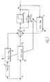
- a second DFE structure shown in Fig. 7 and corresponding for the embodiment of Fig. 6 except as indicated below uses the error e' k to adjust all the coefficients, i.e. those of the adaptive filter 43 as well as those of the forward filter 55 and the feedback filter 51.
- the subtracter 41 of Fig 6 is omitted from Fig. 7.
- the filter adaptation becomes dependent on the training sequence for initialization.
- the delay D is set greater than or equal to L b , the number of taps in feedback filter 51. This prevents the feedback filter portion of the DFE from cancelling the effect of g and hence leading to error propagation. However if multipath is present, the feedback portion helps equalize it. Setting D equal to the number of symbols in one NTSC line will provide the best performance since the correlation between lines is very high. Thus this structure enables the use of the DFE for equalization alone and does not contribute to error propagation when co-channel interference is present.
- Fig. 8 is a block diagram of a television receiver in accordance with the invention.
- the received signal is IF filtered by an IF filter and synchronous detector 81 and then adaptively filtered by a filter 83 to remove the NTSC co-channel interference.
- the trellis decoder 85 then removes the AWGN n k which leaves only the digital signal to be displayed on the display 87.
- the invention provides a method and apparatus for quickly and simply removing signal interference from a digital signal.
- a primary aspect of the invention can be summarized as follows.
- a device and method for removing signal interference from a digital signal by using an adaptive filter which tunes to the periodic components of the interfering signal.
- the output of the adaptive filter is then subtracted from the received signal to produce an error signal.
- This error signal is then used to recursively update the taps of the adaptive filter.
- the invention also relates to the use of the adaptive filter in conjunction with a DFE.
- the invention can be implemented by means of dedicated hardware elements and by means of a processor or several processors controlled by suitable software.
Landscapes
- Engineering & Computer Science (AREA)
- Signal Processing (AREA)
- Multimedia (AREA)
- Power Engineering (AREA)
- Computer Networks & Wireless Communication (AREA)
- Noise Elimination (AREA)
- Filters That Use Time-Delay Elements (AREA)
- Cable Transmission Systems, Equalization Of Radio And Reduction Of Echo (AREA)
- Digital Transmission Methods That Use Modulated Carrier Waves (AREA)
- Dc Digital Transmission (AREA)
- Picture Signal Circuits (AREA)
Claims (20)
- Procédé pour supprimer le brouillage de signal (ik) d'un signal numérique (rk), le procédé comprenant les étapes suivantes :caractérisé en ce que le procédé comprend en outre les étapes suivantes :recevoir le signal numérique qui comprend une pluralité de symboles (ak), du bruit (nk) et un brouillage de signal (ik);retarder (42) le signal numérique reçu;filtrer de manière adaptative le signal retardé en utilisant un filtre adaptatif (43) ayant une pluralité de prises réglables (g1...gLg);soustraire (41) le signal filtré de manière adaptative (ík ) du signal numérique reçu (rk) et produire un signal d'erreur (ek), etutiliser de manière récursive le signal d'erreur (ek) pour régler les prises (g1 ...gLg) du filtre adaptatif (43) pour réduire au minimum l'erreur quadratique moyenne du signal d'erreur (ek) de telle sorte que le filtre adaptatif (43) se syntonise progressivement sur le brouillage de signal (ik) et produise une estimation du brouillage de signal (ík ).
- Procédé suivant la revendication 1, dans lequel g1...gLg représente les prises de filtre adaptatif réglables et l'étape de réglage des prises est effectuée en déterminant la valeur des prises de filtre adaptatif réglables suivant la récurrence de mise à jour suivante gn +1 = gn + 2uen r n , dans laquelle g est un vecteur des prises de filtre adaptatif réglables, u indique la grandeur de pas de l'algorithme LMS, e est le signal d'erreur, r est un vecteur du signal numérique reçu et n se réfère à la valeur d'itération.
- Procédé suivant la revendication 1, dans lequel l'étape de filtrage de manière adaptative produit une sortie définie commeoù ík est l'estimation du brouillage de signal, Lg est le nombre de prises réglables, g1 représente chaque prise de filtre réglable, r est le signal numérique reçu, k représente un symbole particulier du signal numérique reçu et D est la longueur de retard.
- Procédé suivant la revendication 1, le procédé comprenant en outre l'étape d'égalisation à décision réfléchie (510) du signal numérique reçu (rk).
- Procédé suivant la revendication 4, dans lequel l'étape d'égalisation à décision réfléchie (50) comprend les étapes suivantes :filtrer en aval le signal numérique reçu en utilisant un filtre d'aval (55) ayant une pluralité de prises de filtre (f0,f1,...,fLf-1);soustraire (53) l'estimation du brouillage de signal (ík ) du signal filtré (Fk) en aval et générer un premier signal;quantifier (52) le premier signal pour supprimer le brouillage intersymbole;filtrer en retour le signal quantifié (âk) en utilisant un filtre de retour (51) ayant une pluralité de prises de filtre (b1,b2,...,bLb), etsoustraire (53) le signal filtré en retour du premier signal.
- Procédé suivant la revendication 5, dans lequel l'étape de retardement (42) retarde le signal reçu (rk) d'un nombre de symboles (D) au moins égal au nombre de prises (b1,b2,...,bLb) du filtre de retour (51).
- Procédé suivant la revendication 5, dans lequel l'étape de quantification (52) comprend l'étape de soustraction (54) du signal quantifié (âk) du premier signal pour générer un deuxième signal d'erreur (e'k).
- Procédé suivant la revendication 7, le procédé comprenant en outre l'étape de réglage des prises (f0,f1,...,fLf-1; b1,b2,...,bLb) du filtre d'aval (55) et du filtre de retour (51) en utilisant le deuxième signal d'erreur (e'k).
- Système de filtrage (40) pour supprimer le brouillage de signal (ik) d'un signal numérique (rk), le système de filtrage comportant :caractérisé en ce que le système de filtrage (40) comporte en outre :un moyen pour recevoir le signal numérique qui comprend une pluralité de symboles (ak), de bruit (nk) et de brouillage de signal (ik);un moyen (42) pour retarder le signal numérique reçu (rk);un filtre adaptatif (43) ayant une pluralité de prises réglables (g1...gLg) pour filtrer de manière adaptative le signal retardé;un moyen (41) pour soustraire le signal filtré de manière adaptative (ík ) du signal numérique reçu (rk) et pour générer un signal d'erreur (ek), etun moyen (43) pour utiliser de manière récursive le signal d'erreur (ek) pour régler les prises (g1...gLg) du filtre adaptatif (43) pour réduire au minimum l'erreur quadratique moyenne du signal d'erreur (ek) pour syntoniser le filtre adaptatif (43) au brouillage de signal (ik) et pour amener le filtre adaptatif (43) à produire une estimation du brouillage de signal (ík ).
- Système de filtrage suivant la revendication 9, le système de filtrage comportant en outre un égaliseur à décision réfléchie (50) pour supprimer les fantômes du signal numérique reçu (rk).
- Système de filtrage suivant la revendication 10, dans lequel l'égaliseur à décision réfléchie (50) comporte :un filtre d'aval (55) ayant une pluralité de prises de filtre (f0,f1,...,fLf-1) pour filtrer en aval le signal numérique reçu (rk);un moyen (53) pour soustraire l'estimation du brouillage de signal (ík ) du signal filtré en aval (Fk) et pour générer un premier signal;un moyen (52) pour quantifier le premier signal afin de supprimer le brouillage intersymbole;un filtre de retour (51) ayant une pluralité de prises de filtre (b1,b2,...,bLb) pour filtrer en retour le signal quantifié (âk), etun moyen (53) pour soustraire le signal filtré en retour du premier signal.
- Système de filtrage suivant la revendication 10, dans lequel le moyen à retard (42) a été agencé pour retarder le signal numérique reçu (rk) d'un nombre de symboles (D) qui est au moins égal au nombre de prises du filtre de retour (50).
- Système de filtrage suivant la revendication 12, le système de filtrage comprenant en outre un moyen (54) pour soustraire le signal quantifié (âk) du premier signal afin de générer un deuxième signal d'erreur (e'k).
- Système de filtrage suivant la revendication 13, le système de filtrage comprenant en outre un moyen pour régler les prises (f0,f1,...,fLf-1; (b1,b2,...,bLb) du filtre d'aval (55) et du filtre de retour (51) en utilisant un algorithme adaptatif.
- Système de filtrage suivant la revendication 13, le système de filtrage comprenant en outre un moyen pour régler les prises du filtre d'aval et du filtre de retour en utilisant un algorithme LMS qui dépend du deuxième signal d'erreur.
- Procédé pour supprimer le brouillage de signal (ik) d'un signal numérique (rk), le procédé comprenant les étapes suivantes :caractérisé en ce que le procédé comprend en outre les étapes suivantes :recevoir le signal numérique (rk), lequel signal numérique contient une pluralité de symboles (ak), du bruit (nk) et du brouillage de signal (ik);retarder (42) le signal numérique reçu (rk);filtrer de manière adaptative le signal retardé en utilisant un filtre adaptatif (43) ayant une pluralité de prises réglables (g1...gLg);filtrer en aval le signal numérique reçu (rk) en utilisant un filtre d'aval (55) avec une pluralité de prises réglables (g1...gLg);soustraire (53) le signal filtré de manière adaptative (ík ) du signal filtre d'aval (Fk) et générer un premier signal;quantifier (52) le premier signal;filtrer en retour le signal quantifié en utilisant un filtre de retour (51) avec une pluralité de prises réglables (b1, b2,..., bLB);soustraire (54) le signal quantifié filtré (âk) du premier signal et générer un signal d'erreur (e'k), etrégler les prises réglables du filtre adaptatif (43) en utilisant le signal d'erreur (e'k) et un algorithme adaptatif de telle sorte que le filtre adaptatif (43) se syntonise sur le brouillage de signal (ik) et produise une estimation de brouillage de signal (ík ).
- Procédé suivant la revendication 16, dans lequel l'étape de réglage comprend en outre l'étape de réglage des prises (f0,f1,...,fLf-1; b1,b2,...,bLb) du filtre d'aval (55) et du filtre de retour (51) en utilisant le signal d'erreur (e'k) et l'algorithme adaptatif.
- Système de filtrage pour supprimer le brouillage de signal (ik) d'un signal numérique (rk) comportant :caractérisé en ce que le système de filtrage comporte en outre :un moyen pour recevoir le signal numérique (rk) lequel signal numérique contient une pluralité de symboles (ak), du bruit (nk) et du brouillage de signal (ik);un moyen (42) pour retarder le signal numérique reçu (rk);un filtre adaptatif (43) ayant une pluralité de prises réglables (g1...gLg) pour filtrer de manière adaptative le signal retardé;un filtre d'aval (55) ayant une pluralité de prises réglables (g1...gLg) pour filtrer en aval le signal numérique reçu (rk);un premier moyen de soustraction (53) pour soustraire le signal filtré de manière adaptative (ík ) du signal filtré en aval (Fk) et générer un premier signal;un moyen (52) pour quantifier le premier signal;un filtre de retour (51) ayant une pluralité de prises réglables (g1...gLg) pour filtrer en retour le signal quantifié;un deuxième moyen de soustraction (54) pour soustraire le signal quantifié filtré (âk) du premier signal et générer un signal d'erreur (e'k), etun moyen de réglage pour régler les prises réglables (g1...gLg) du filtre adaptatif (43) en utilisant le signal d'erreur (e'k) et un algorithme adaptatif pour syntoniser le filtre adaptatif (43) sur le brouillage de signal (ik) et pour amener le filtre adaptatif (43) à produire une estimation du brouillage de signal (ík ).
- Système de filtrage suivant la revendication 18, dans lequel le moyen de filtrage contient un moyen pour régler les prises (f0,f1,...,fLf-1; b1,b2,...,bLb) du filtre d'aval (55) et du filtre de retour (51) en utilisant le signal d'erreur (e'k) et l'algorithme adaptatif.
- Récepteur de télévision comprenant un système de filtrage suivant l'une quelconque des revendications 9, 10, 11, 12, 13, 14, 15, 18, 19 pour supprimer le brouillage de signal d'un signal numérique.
Applications Claiming Priority (3)
| Application Number | Priority Date | Filing Date | Title |
|---|---|---|---|
| US08/366,138 US5572262A (en) | 1994-12-29 | 1994-12-29 | Receiver based methods and devices for combating co-channel NTSC interference in digital transmission |
| US366138 | 1994-12-29 | ||
| PCT/IB1995/001133 WO1996021304A2 (fr) | 1994-12-29 | 1995-12-15 | Lutte contre le brouillage des signaux en transmission numerique |
Publications (2)
| Publication Number | Publication Date |
|---|---|
| EP0748551A1 EP0748551A1 (fr) | 1996-12-18 |
| EP0748551B1 true EP0748551B1 (fr) | 2003-05-21 |
Family
ID=23441813
Family Applications (1)
| Application Number | Title | Priority Date | Filing Date |
|---|---|---|---|
| EP95938574A Expired - Lifetime EP0748551B1 (fr) | 1994-12-29 | 1995-12-15 | Lutte contre le brouillage des signaux en transmission numerique |
Country Status (6)
| Country | Link |
|---|---|
| US (2) | US5572262A (fr) |
| EP (1) | EP0748551B1 (fr) |
| JP (1) | JP3658409B2 (fr) |
| CA (1) | CA2184393C (fr) |
| DE (1) | DE69530837T2 (fr) |
| WO (1) | WO1996021304A2 (fr) |
Families Citing this family (117)
| Publication number | Priority date | Publication date | Assignee | Title |
|---|---|---|---|---|
| US5857998A (en) * | 1994-06-30 | 1999-01-12 | Boston Scientific Corporation | Stent and therapeutic delivery system |
| US5572262A (en) * | 1994-12-29 | 1996-11-05 | Philips Electronics North America Corporation | Receiver based methods and devices for combating co-channel NTSC interference in digital transmission |
| KR0172885B1 (ko) * | 1995-08-25 | 1999-03-20 | 구자홍 | 에이치디티브이용 통합 트렐리스 디코더 |
| US5914988A (en) * | 1996-04-09 | 1999-06-22 | Thomson Multimedia S.A. | Digital packet data trellis decoder |
| KR100366698B1 (ko) * | 1996-06-07 | 2003-03-10 | 삼성전자 주식회사 | 데이타 저장기기의 신호검출방법 및 장치 |
| US6952444B1 (en) * | 1996-07-19 | 2005-10-04 | Texas Instruments Incorporated | Blind DFE and phase correction |
| US5878086A (en) * | 1996-09-19 | 1999-03-02 | Philips Electronics North America Corporation | Method and apparatus for producing a deterministic sequence from an IIR filter |
| US6023306A (en) * | 1996-10-02 | 2000-02-08 | Samsung Electronics Co. Ltd. | NTSC interference detectors using comb filters that suppress digital TV pilot carrier for NTSC extraction |
| US5742642A (en) * | 1996-10-29 | 1998-04-21 | Telefonaktiebolaget Lm Ericsson | Signal processing method and apparatus for reducing equalizer error |
| US6177951B1 (en) * | 1996-12-18 | 2001-01-23 | Philips Electronics North America Corporation | Digital receiver which utilizes a rejection filter for cancellation of known co-channel interference and an equalizer for equalizing multipath channels without attempting to equalize the co-channel interference |
| US5923378A (en) * | 1997-03-21 | 1999-07-13 | Samsung Electronics Co., Ltd. | Using intercarrier signals for detecting NTSC interference in digital TV receivers |
| US6011813A (en) * | 1997-06-23 | 2000-01-04 | Philips Electronics North America Corporation | Blind equalization method and apparatus having reduced complexity |
| US6330275B1 (en) | 1997-06-23 | 2001-12-11 | Paradyne Corporation | Method and apparatus for overcoming periodic disturbances in digital subscriber loops |
| KR100247967B1 (ko) * | 1997-07-09 | 2000-03-15 | 윤종용 | 동일채널간섭검출기와그방법 |
| KR100238301B1 (ko) * | 1997-07-10 | 2000-01-15 | 윤종용 | 동일채널 간섭 검출기와 그 방법 |
| US6011814A (en) * | 1997-09-30 | 2000-01-04 | Paradyne Corporation | Adaptive comb filter and decision feedback equalizer for noise suppression |
| US6285709B1 (en) * | 1997-10-31 | 2001-09-04 | 3 Com Corporation | Error filtering in a hybrid equalizer system |
| EP0921664B1 (fr) * | 1997-11-03 | 2005-06-08 | Alcatel | Procédé de transmission d'information numérique |
| DE19803235A1 (de) * | 1998-01-28 | 1999-07-29 | Siemens Ag | Vorrichtung und Verfahren zur Veränderung des Rauschverhaltens in einem Empfänger eines Datenübertragungssystems |
| AU3218699A (en) | 1998-03-30 | 1999-10-18 | 3Com Corporation | Low complexity frequency estimator and interference cancellation method and device |
| US6141783A (en) * | 1998-04-10 | 2000-10-31 | International Business Machines Corporation | Error propagation limiting encoder/decoder for multilevel decision feedback equalization |
| US6680971B1 (en) * | 1998-05-18 | 2004-01-20 | Sarnoff Corporation | Passband equalizer for a vestigial sideband signal receiver |
| US6724844B1 (en) | 1998-06-30 | 2004-04-20 | Koninklijke Philips Electronics N.V. | Method and device for improving DFE performance in a trellis-coded system |
| GB9815907D0 (en) * | 1998-07-21 | 1998-09-16 | British Broadcasting Corp | Improvements in colour displays |
| US7515896B1 (en) | 1998-10-21 | 2009-04-07 | Parkervision, Inc. | Method and system for down-converting an electromagnetic signal, and transforms for same, and aperture relationships |
| US6091940A (en) | 1998-10-21 | 2000-07-18 | Parkervision, Inc. | Method and system for frequency up-conversion |
| US6694128B1 (en) | 1998-08-18 | 2004-02-17 | Parkervision, Inc. | Frequency synthesizer using universal frequency translation technology |
| US6061551A (en) | 1998-10-21 | 2000-05-09 | Parkervision, Inc. | Method and system for down-converting electromagnetic signals |
| US6327302B1 (en) * | 1998-08-28 | 2001-12-04 | Ericsson Inc. | Fast adaptive equalizer for wireless communication systems |
| US6434233B1 (en) * | 1998-09-30 | 2002-08-13 | Conexant Systems, Inc. | Method and apparatus for canceling periodic interference signals in a digital data communication system |
| US6061555A (en) | 1998-10-21 | 2000-05-09 | Parkervision, Inc. | Method and system for ensuring reception of a communications signal |
| US7027786B1 (en) | 1998-10-21 | 2006-04-11 | Parkervision, Inc. | Carrier and clock recovery using universal frequency translation |
| US6370371B1 (en) | 1998-10-21 | 2002-04-09 | Parkervision, Inc. | Applications of universal frequency translation |
| US6813485B2 (en) | 1998-10-21 | 2004-11-02 | Parkervision, Inc. | Method and system for down-converting and up-converting an electromagnetic signal, and transforms for same |
| US6542722B1 (en) | 1998-10-21 | 2003-04-01 | Parkervision, Inc. | Method and system for frequency up-conversion with variety of transmitter configurations |
| US6560301B1 (en) | 1998-10-21 | 2003-05-06 | Parkervision, Inc. | Integrated frequency translation and selectivity with a variety of filter embodiments |
| US7236754B2 (en) | 1999-08-23 | 2007-06-26 | Parkervision, Inc. | Method and system for frequency up-conversion |
| US6049706A (en) | 1998-10-21 | 2000-04-11 | Parkervision, Inc. | Integrated frequency translation and selectivity |
| US7039372B1 (en) | 1998-10-21 | 2006-05-02 | Parkervision, Inc. | Method and system for frequency up-conversion with modulation embodiments |
| US7295826B1 (en) | 1998-10-21 | 2007-11-13 | Parkervision, Inc. | Integrated frequency translation and selectivity with gain control functionality, and applications thereof |
| US6438164B2 (en) * | 1998-11-03 | 2002-08-20 | Broadcom Corporation | Technique for minimizing decision feedback equalizer wordlength in the presence of a DC component |
| US6704549B1 (en) | 1999-03-03 | 2004-03-09 | Parkvision, Inc. | Multi-mode, multi-band communication system |
| US6704558B1 (en) | 1999-01-22 | 2004-03-09 | Parkervision, Inc. | Image-reject down-converter and embodiments thereof, such as the family radio service |
| US7006805B1 (en) | 1999-01-22 | 2006-02-28 | Parker Vision, Inc. | Aliasing communication system with multi-mode and multi-band functionality and embodiments thereof, such as the family radio service |
| US6879817B1 (en) | 1999-04-16 | 2005-04-12 | Parkervision, Inc. | DC offset, re-radiation, and I/Q solutions using universal frequency translation technology |
| US6873836B1 (en) | 1999-03-03 | 2005-03-29 | Parkervision, Inc. | Universal platform module and methods and apparatuses relating thereto enabled by universal frequency translation technology |
| US6853690B1 (en) | 1999-04-16 | 2005-02-08 | Parkervision, Inc. | Method, system and apparatus for balanced frequency up-conversion of a baseband signal and 4-phase receiver and transceiver embodiments |
| US6526093B1 (en) | 1999-03-04 | 2003-02-25 | Mitsubishi Electric Research Laboratories, Inc | Method and apparatus for equalizing a digital signal received via multiple transmission paths |
| US7110435B1 (en) | 1999-03-15 | 2006-09-19 | Parkervision, Inc. | Spread spectrum applications of universal frequency translation |
| JP3859386B2 (ja) * | 1999-03-31 | 2006-12-20 | 三菱電機株式会社 | 波形等化器、波形等化装置及び受信装置 |
| US7693230B2 (en) | 1999-04-16 | 2010-04-06 | Parkervision, Inc. | Apparatus and method of differential IQ frequency up-conversion |
| US7110444B1 (en) | 1999-08-04 | 2006-09-19 | Parkervision, Inc. | Wireless local area network (WLAN) using universal frequency translation technology including multi-phase embodiments and circuit implementations |
| US7065162B1 (en) | 1999-04-16 | 2006-06-20 | Parkervision, Inc. | Method and system for down-converting an electromagnetic signal, and transforms for same |
| JP3841588B2 (ja) * | 1999-05-19 | 2006-11-01 | 富士通株式会社 | 多値判定帰還等化における誤り伝播検出抑制方法及び、これを用いた記憶装置 |
| US7054296B1 (en) | 1999-08-04 | 2006-05-30 | Parkervision, Inc. | Wireless local area network (WLAN) technology and applications including techniques of universal frequency translation |
| US8295406B1 (en) | 1999-08-04 | 2012-10-23 | Parkervision, Inc. | Universal platform module for a plurality of communication protocols |
| US7072390B1 (en) | 1999-08-04 | 2006-07-04 | Parkervision, Inc. | Wireless local area network (WLAN) using universal frequency translation technology including multi-phase embodiments |
| GB2355629B (en) * | 1999-10-18 | 2004-02-11 | Mitel Corp | Precursor decision feedback equalizer (PDFE) |
| EP1145475A1 (fr) * | 1999-10-21 | 2001-10-17 | Koninklijke Philips Electronics N.V. | Recepteur de formation de faisceaux numerique adaptatif destine a l'amelioration de la reception de signaux |
| US7082171B1 (en) | 1999-11-24 | 2006-07-25 | Parkervision, Inc. | Phase shifting applications of universal frequency translation |
| US6963734B2 (en) | 1999-12-22 | 2005-11-08 | Parkervision, Inc. | Differential frequency down-conversion using techniques of universal frequency translation technology |
| US6590933B1 (en) * | 1999-12-27 | 2003-07-08 | Tioga Technologies Ltd. | Adaptive decision-feedback equalizer with error-predictor for improved convergence |
| US7292835B2 (en) | 2000-01-28 | 2007-11-06 | Parkervision, Inc. | Wireless and wired cable modem applications of universal frequency translation technology |
| US7010286B2 (en) | 2000-04-14 | 2006-03-07 | Parkervision, Inc. | Apparatus, system, and method for down-converting and up-converting electromagnetic signals |
| US7554508B2 (en) | 2000-06-09 | 2009-06-30 | Parker Vision, Inc. | Phased array antenna applications on universal frequency translation |
| US6973144B1 (en) * | 2000-09-12 | 2005-12-06 | Lucent Technologies Inc. | Apparatus and method for channel estimation used for link adaption with error feedback |
| US7454453B2 (en) | 2000-11-14 | 2008-11-18 | Parkervision, Inc. | Methods, systems, and computer program products for parallel correlation and applications thereof |
| US7010559B2 (en) | 2000-11-14 | 2006-03-07 | Parkervision, Inc. | Method and apparatus for a parallel correlator and applications thereof |
| US6934345B2 (en) * | 2001-01-17 | 2005-08-23 | Adtran, Inc. | Apparatus, method and system for correlated noise reduction in a trellis coded environment |
| DE10101950C1 (de) * | 2001-01-17 | 2003-01-23 | Infineon Technologies Ag | Entscheidungsrückgekoppelte Entzerrervorrichtung |
| US20020186764A1 (en) * | 2001-04-06 | 2002-12-12 | Sarnoff Corporation | Method and apparatus for equalizing a radio frequency signal |
| US6734920B2 (en) | 2001-04-23 | 2004-05-11 | Koninklijke Philips Electronics N.V. | System and method for reducing error propagation in a decision feedback equalizer of ATSC VSB receiver |
| US7349469B1 (en) * | 2001-08-17 | 2008-03-25 | Ati Research, Inc. | DC offset correction for constant modulus equalization |
| JP3856101B2 (ja) | 2001-09-03 | 2006-12-13 | 日本電気株式会社 | 受信波形整形機能を有する光受信装置 |
| US6956914B2 (en) * | 2001-09-19 | 2005-10-18 | Gennum Corporation | Transmit amplitude independent adaptive equalizer |
| US7072427B2 (en) | 2001-11-09 | 2006-07-04 | Parkervision, Inc. | Method and apparatus for reducing DC offsets in a communication system |
| US7085335B2 (en) | 2001-11-09 | 2006-08-01 | Parkervision, Inc. | Method and apparatus for reducing DC offsets in a communication system |
| US20030107986A1 (en) * | 2001-12-11 | 2003-06-12 | Sarnoff Corporation | Method and apparatus for demodulating orthogonal frequency division multiplexed signals |
| US7027538B2 (en) | 2002-02-14 | 2006-04-11 | Koninklijke Philips Electronics N.V. | Method and system for joint decision feedback equalization and complementary code key decoding using a trellis |
| US7092036B2 (en) * | 2002-04-16 | 2006-08-15 | Thomson Licensing | Equalizer system including a comb filter in an HDTV system |
| US7107303B2 (en) * | 2002-05-23 | 2006-09-12 | Analog Devices, Inc. | Sparse echo canceller |
| US6975848B2 (en) | 2002-06-04 | 2005-12-13 | Parkervision, Inc. | Method and apparatus for DC offset removal in a radio frequency communication channel |
| US7321640B2 (en) | 2002-06-07 | 2008-01-22 | Parkervision, Inc. | Active polyphase inverter filter for quadrature signal generation |
| EP1540817A4 (fr) * | 2002-06-12 | 2009-05-27 | Dsp Group Inc | Demodulation cck via egalisateur a decision retroactive de symboles |
| US7379883B2 (en) | 2002-07-18 | 2008-05-27 | Parkervision, Inc. | Networking methods and systems |
| US7460584B2 (en) | 2002-07-18 | 2008-12-02 | Parkervision, Inc. | Networking methods and systems |
| US7764752B2 (en) * | 2002-09-27 | 2010-07-27 | Ikanos Communications, Inc. | Method and system for reducing interferences due to handshake tones |
| US7545859B2 (en) * | 2004-01-14 | 2009-06-09 | L-3 Communications Integrated Systems L.P. | Adaptive channel equalization technique and method for wideband passive digital receivers |
| US7327808B2 (en) * | 2004-03-17 | 2008-02-05 | Faraday Technology Corp. | Pipelined adaptive decision feedback equalizer |
| US7716046B2 (en) | 2004-10-26 | 2010-05-11 | Qnx Software Systems (Wavemakers), Inc. | Advanced periodic signal enhancement |
| US8306821B2 (en) * | 2004-10-26 | 2012-11-06 | Qnx Software Systems Limited | Sub-band periodic signal enhancement system |
| US8543390B2 (en) | 2004-10-26 | 2013-09-24 | Qnx Software Systems Limited | Multi-channel periodic signal enhancement system |
| US7949520B2 (en) | 2004-10-26 | 2011-05-24 | QNX Software Sytems Co. | Adaptive filter pitch extraction |
| US7610196B2 (en) * | 2004-10-26 | 2009-10-27 | Qnx Software Systems (Wavemakers), Inc. | Periodic signal enhancement system |
| US7680652B2 (en) * | 2004-10-26 | 2010-03-16 | Qnx Software Systems (Wavemakers), Inc. | Periodic signal enhancement system |
| US8170879B2 (en) | 2004-10-26 | 2012-05-01 | Qnx Software Systems Limited | Periodic signal enhancement system |
| US7599431B1 (en) * | 2004-11-24 | 2009-10-06 | Xilinx, Inc. | Combined decision feedback equalization and linear equalization |
| US7369155B2 (en) * | 2005-05-16 | 2008-05-06 | Mediatek Incorporation | Apparatus and method for rejecting co-channel interference signal |
| US8850154B2 (en) | 2007-09-11 | 2014-09-30 | 2236008 Ontario Inc. | Processing system having memory partitioning |
| US8904400B2 (en) | 2007-09-11 | 2014-12-02 | 2236008 Ontario Inc. | Processing system having a partitioning component for resource partitioning |
| US8694310B2 (en) | 2007-09-17 | 2014-04-08 | Qnx Software Systems Limited | Remote control server protocol system |
| US8209514B2 (en) | 2008-02-04 | 2012-06-26 | Qnx Software Systems Limited | Media processing system having resource partitioning |
| CN101662576B (zh) * | 2008-08-27 | 2011-07-20 | 扬智科技股份有限公司 | 适用于消除同频道干扰的信号处理电路与方法 |
| US9912375B1 (en) | 2008-09-25 | 2018-03-06 | Aquantia Corp. | Cancellation of alien interference in communication systems |
| US8625704B1 (en) | 2008-09-25 | 2014-01-07 | Aquantia Corporation | Rejecting RF interference in communication systems |
| GB2479173A (en) | 2010-03-31 | 2011-10-05 | Sony Corp | Reducing interference at a television receiver by identifying channel maps |
| US9118469B2 (en) | 2010-05-28 | 2015-08-25 | Aquantia Corp. | Reducing electromagnetic interference in a received signal |
| US8891595B1 (en) | 2010-05-28 | 2014-11-18 | Aquantia Corp. | Electromagnetic interference reduction in wireline applications using differential signal compensation |
| US8724678B2 (en) | 2010-05-28 | 2014-05-13 | Aquantia Corporation | Electromagnetic interference reduction in wireline applications using differential signal compensation |
| US8792597B2 (en) | 2010-06-18 | 2014-07-29 | Aquantia Corporation | Reducing electromagnetic interference in a receive signal with an analog correction signal |
| US8861663B1 (en) * | 2011-12-01 | 2014-10-14 | Aquantia Corporation | Correlated noise canceller for high-speed ethernet receivers |
| US8780277B2 (en) | 2012-05-22 | 2014-07-15 | Sony Corporation | Television receiver, television controller circuitry and method |
| GB2502297A (en) * | 2012-05-22 | 2013-11-27 | Sony Corp | Television receiver for suppressing signals on a frequency channel when TV signals are absent |
| US8929468B1 (en) | 2012-06-14 | 2015-01-06 | Aquantia Corp. | Common-mode detection with magnetic bypass |
| US9602317B1 (en) * | 2015-10-12 | 2017-03-21 | Qualcomm Incorporated | Apparatus and method for combining currents from passive equalizer in sense amplifier |
| US9843464B2 (en) | 2015-10-14 | 2017-12-12 | Maxlinear Asia Singapore Private Limited | Wireless backhaul |
| US12360086B2 (en) | 2021-06-07 | 2025-07-15 | The Boeing Company | Active temperature compensation technique for structural health monitoring sensors |
Family Cites Families (19)
| Publication number | Priority date | Publication date | Assignee | Title |
|---|---|---|---|---|
| US3889108A (en) * | 1974-07-25 | 1975-06-10 | Us Navy | Adaptive low pass filter |
| US4524424A (en) * | 1982-02-18 | 1985-06-18 | Rockwell International Corporation | Adaptive spectrum shaping filter |
| NL8700125A (nl) * | 1987-01-20 | 1988-08-16 | Philips Nv | Inrichting voor het bestrijden van intersymboolinterferentie en ruis. |
| US5031194A (en) * | 1989-08-11 | 1991-07-09 | Bell Communications Research, Inc. | Wideband digital equalizers for subscriber loops |
| DE69121829T2 (de) * | 1990-10-09 | 1997-03-20 | Philips Electronics Nv | Kodier/Dekodier-Einrichtung und Verfahren für durch kodierte Modulation übertragene, digitale Signale |
| US5086340A (en) * | 1990-10-19 | 1992-02-04 | Zenith Electronics Corporation | Co-channel interference reduction system for digital high definition television |
| US5195106A (en) * | 1990-11-14 | 1993-03-16 | Motorola, Inc. | Method for channel adaptive detecting/equalize |
| DE4038251A1 (de) * | 1990-11-30 | 1992-06-04 | Philips Patentverwaltung | Entzerrer fuer ein digitales uebertragungssystem |
| FR2674709A1 (fr) * | 1991-03-29 | 1992-10-02 | Philips Electronique Lab | Decodeur multietages. |
| CA2076099A1 (fr) * | 1991-09-03 | 1993-03-04 | Howard Leroy Lester | Alignement automatique d'emissions diffusees en simultaneite |
| US5307517A (en) * | 1991-10-17 | 1994-04-26 | Rich David A | Adaptive notch filter for FM interference cancellation |
| JPH05183456A (ja) * | 1991-12-27 | 1993-07-23 | Nec Corp | 制御信号発生装置 |
| JP2762836B2 (ja) * | 1992-04-09 | 1998-06-04 | 日本電気株式会社 | 干渉波除去装置 |
| US5453797A (en) * | 1993-02-22 | 1995-09-26 | Massachusetts Institute Of Technology | Method and apparatus for decoding broadcast digital HDTV in the presence of quasi-cyclostationary interference |
| DE69327900T2 (de) * | 1993-06-09 | 2000-07-06 | Stmicroelectronics S.R.L., Agrate Brianza | Adaptives Verfahren zur Entfernung von Geisterbildern in Videosignalen |
| US5452015A (en) * | 1994-02-10 | 1995-09-19 | Philips Electronics North America Corporation | Method and apparatus for combating co-channel NTSC interference for digital TV transmission |
| US5539774A (en) * | 1994-06-15 | 1996-07-23 | International Business Machines Corporation | Dual decision equalization method and device |
| US5550596A (en) * | 1994-11-25 | 1996-08-27 | Thomson Multimedia Sa | Digital television signal processing system including a co-channel rejection filter |
| US5572262A (en) * | 1994-12-29 | 1996-11-05 | Philips Electronics North America Corporation | Receiver based methods and devices for combating co-channel NTSC interference in digital transmission |
-
1994
- 1994-12-29 US US08/366,138 patent/US5572262A/en not_active Expired - Lifetime
-
1995
- 1995-12-15 WO PCT/IB1995/001133 patent/WO1996021304A2/fr not_active Ceased
- 1995-12-15 DE DE69530837T patent/DE69530837T2/de not_active Expired - Fee Related
- 1995-12-15 JP JP52082496A patent/JP3658409B2/ja not_active Expired - Lifetime
- 1995-12-15 EP EP95938574A patent/EP0748551B1/fr not_active Expired - Lifetime
- 1995-12-15 CA CA002184393A patent/CA2184393C/fr not_active Expired - Fee Related
-
1996
- 1996-07-18 US US08/683,331 patent/US5777692A/en not_active Expired - Lifetime
Also Published As
| Publication number | Publication date |
|---|---|
| CA2184393C (fr) | 2006-07-04 |
| CA2184393A1 (fr) | 1996-07-11 |
| MX9603694A (es) | 1997-07-31 |
| JP3658409B2 (ja) | 2005-06-08 |
| WO1996021304A3 (fr) | 1996-09-06 |
| US5572262A (en) | 1996-11-05 |
| JPH10500830A (ja) | 1998-01-20 |
| EP0748551A1 (fr) | 1996-12-18 |
| DE69530837D1 (de) | 2003-06-26 |
| WO1996021304A2 (fr) | 1996-07-11 |
| US5777692A (en) | 1998-07-07 |
| DE69530837T2 (de) | 2004-02-26 |
Similar Documents
| Publication | Publication Date | Title |
|---|---|---|
| EP0748551B1 (fr) | Lutte contre le brouillage des signaux en transmission numerique | |
| EP0693243B1 (fr) | Appareil permettant d'eliminer les parasites ntsc dans un meme canal dans la transmission televisuelle numerique | |
| EP0891667B1 (fr) | Recepteur numerique | |
| US5453797A (en) | Method and apparatus for decoding broadcast digital HDTV in the presence of quasi-cyclostationary interference | |
| US6122015A (en) | Method and apparatus for filtering digital television signals | |
| US5602602A (en) | Method and apparatus for combating co-channel NTSC interference for digital TV transmission having a simplified rejection filter | |
| KR930010427B1 (ko) | 다중로 왜곡 보정장치 | |
| US5572249A (en) | Method and apparatus for optimal NTSC rejection filtering and transmitter and receiver comprising same | |
| KR0145439B1 (ko) | 고선명 텔레비젼용 적응등화기의 동작제어 방법 및 장치 | |
| KR0153610B1 (ko) | 영상 캐리어와 직각 위상을 이루는 캐리어를 변조한 신호에서의 고스트 억압 장치 | |
| JP2912908B2 (ja) | 同一チャンネル干渉除去器及びその方法 | |
| CA2236083C (fr) | Eliminateur de parasites de canal commun et methode de commande de cet eliminateur | |
| KR100309098B1 (ko) | 기준신호를갖는변복조방식디지털통신시스템수신장치에서의신호처리방법및장치와동일채널간섭신호제거를위한방법및장치 | |
| CN100463505C (zh) | 抑制同频道干扰信号的方法及相关的滤波系统与接收器 | |
| MXPA96003694A (en) | Combat of signal interference in digi transmission | |
| JPH06225183A (ja) | ゴースト除去装置 | |
| KR100556400B1 (ko) | 디지털 방송 수신 시스템 및 이 수신 시스템에서의ntsc 신호 제거 방법 | |
| KR20020061839A (ko) | 디지털 티브이의 ntsc 인접 채널 간섭 제거 장치 | |
| Roy et al. | Ghost cancellation for advanced compatible TV system using complementary sequences | |
| Gitlin et al. | GHOST CANCELLATION OF ANALOG TV SIGNALS: WITH APPLICATIONS TO IDTV, EDTV, AND HDTV | |
| MXPA99003975A (en) | Device and method for eliminating channel interference signs from contiguo in modulation / demodulation receivers having a reference sign |
Legal Events
| Date | Code | Title | Description |
|---|---|---|---|
| PUAI | Public reference made under article 153(3) epc to a published international application that has entered the european phase |
Free format text: ORIGINAL CODE: 0009012 |
|
| AK | Designated contracting states |
Kind code of ref document: A1 Designated state(s): DE FR GB IT |
|
| RIN1 | Information on inventor provided before grant (corrected) |
Inventor name: TICHELAAR, JOHANNES, IJZEBRAND Inventor name: GHOSH, MONISHA, GHOSH |
|
| 17P | Request for examination filed |
Effective date: 19970113 |
|
| 17Q | First examination report despatched |
Effective date: 20010328 |
|
| GRAH | Despatch of communication of intention to grant a patent |
Free format text: ORIGINAL CODE: EPIDOS IGRA |
|
| GRAH | Despatch of communication of intention to grant a patent |
Free format text: ORIGINAL CODE: EPIDOS IGRA |
|
| GRAA | (expected) grant |
Free format text: ORIGINAL CODE: 0009210 |
|
| AK | Designated contracting states |
Designated state(s): DE FR GB IT |
|
| REG | Reference to a national code |
Ref country code: GB Ref legal event code: FG4D |
|
| REF | Corresponds to: |
Ref document number: 69530837 Country of ref document: DE Date of ref document: 20030626 Kind code of ref document: P |
|
| ET | Fr: translation filed | ||
| PLBE | No opposition filed within time limit |
Free format text: ORIGINAL CODE: 0009261 |
|
| STAA | Information on the status of an ep patent application or granted ep patent |
Free format text: STATUS: NO OPPOSITION FILED WITHIN TIME LIMIT |
|
| 26N | No opposition filed |
Effective date: 20040224 |
|
| PGFP | Annual fee paid to national office [announced via postgrant information from national office to epo] |
Ref country code: IT Payment date: 20061231 Year of fee payment: 12 |
|
| REG | Reference to a national code |
Ref country code: GB Ref legal event code: 732E Free format text: REGISTERED BETWEEN 20090312 AND 20090318 |
|
| PGFP | Annual fee paid to national office [announced via postgrant information from national office to epo] |
Ref country code: FR Payment date: 20081212 Year of fee payment: 14 |
|
| PGFP | Annual fee paid to national office [announced via postgrant information from national office to epo] |
Ref country code: DE Payment date: 20081219 Year of fee payment: 14 |
|
| PGFP | Annual fee paid to national office [announced via postgrant information from national office to epo] |
Ref country code: GB Payment date: 20081216 Year of fee payment: 14 |
|
| PG25 | Lapsed in a contracting state [announced via postgrant information from national office to epo] |
Ref country code: IT Free format text: LAPSE BECAUSE OF NON-PAYMENT OF DUE FEES Effective date: 20071215 |
|
| GBPC | Gb: european patent ceased through non-payment of renewal fee |
Effective date: 20091215 |
|
| REG | Reference to a national code |
Ref country code: FR Ref legal event code: ST Effective date: 20100831 |
|
| PG25 | Lapsed in a contracting state [announced via postgrant information from national office to epo] |
Ref country code: FR Free format text: LAPSE BECAUSE OF NON-PAYMENT OF DUE FEES Effective date: 20091231 |
|
| PG25 | Lapsed in a contracting state [announced via postgrant information from national office to epo] |
Ref country code: DE Free format text: LAPSE BECAUSE OF NON-PAYMENT OF DUE FEES Effective date: 20100701 |
|
| PG25 | Lapsed in a contracting state [announced via postgrant information from national office to epo] |
Ref country code: GB Free format text: LAPSE BECAUSE OF NON-PAYMENT OF DUE FEES Effective date: 20091215 |