EP0748582B1 - Vorrichtung zur Verbindung eines Häckslerwerkzeugs mit einem Rotor; landwirtschaftliche Häckselmaschine versehen mit einer solchen Vorrichtung - Google Patents
Vorrichtung zur Verbindung eines Häckslerwerkzeugs mit einem Rotor; landwirtschaftliche Häckselmaschine versehen mit einer solchen Vorrichtung Download PDFInfo
- Publication number
- EP0748582B1 EP0748582B1 EP19960440047 EP96440047A EP0748582B1 EP 0748582 B1 EP0748582 B1 EP 0748582B1 EP 19960440047 EP19960440047 EP 19960440047 EP 96440047 A EP96440047 A EP 96440047A EP 0748582 B1 EP0748582 B1 EP 0748582B1
- Authority
- EP
- European Patent Office
- Prior art keywords
- rotor
- central core
- intermediate support
- intended
- connecting device
- Prior art date
- Legal status (The legal status is an assumption and is not a legal conclusion. Google has not performed a legal analysis and makes no representation as to the accuracy of the status listed.)
- Expired - Lifetime
Links
- 230000000295 complement effect Effects 0.000 claims description 4
- 241000196324 Embryophyta Species 0.000 description 12
- 230000000903 blocking effect Effects 0.000 description 8
- 239000002689 soil Substances 0.000 description 2
- 208000032369 Primary transmission Diseases 0.000 description 1
- 208000032370 Secondary transmission Diseases 0.000 description 1
- 235000002595 Solanum tuberosum Nutrition 0.000 description 1
- 244000061456 Solanum tuberosum Species 0.000 description 1
- 238000012550 audit Methods 0.000 description 1
- 230000005540 biological transmission Effects 0.000 description 1
- 230000008878 coupling Effects 0.000 description 1
- 238000010168 coupling process Methods 0.000 description 1
- 238000005859 coupling reaction Methods 0.000 description 1
- 238000012423 maintenance Methods 0.000 description 1
- 239000000463 material Substances 0.000 description 1
- 238000012986 modification Methods 0.000 description 1
- 230000004048 modification Effects 0.000 description 1
- 235000012015 potatoes Nutrition 0.000 description 1
- 230000002787 reinforcement Effects 0.000 description 1
- 238000006467 substitution reaction Methods 0.000 description 1
Images


Classifications
-
- A—HUMAN NECESSITIES
- A01—AGRICULTURE; FORESTRY; ANIMAL HUSBANDRY; HUNTING; TRAPPING; FISHING
- A01D—HARVESTING; MOWING
- A01D34/00—Mowers; Mowing apparatus of harvesters
- A01D34/01—Mowers; Mowing apparatus of harvesters characterised by features relating to the type of cutting apparatus
- A01D34/412—Mowers; Mowing apparatus of harvesters characterised by features relating to the type of cutting apparatus having rotating cutters
- A01D34/42—Mowers; Mowing apparatus of harvesters characterised by features relating to the type of cutting apparatus having rotating cutters having cutters rotating about a horizontal axis, e.g. cutting-cylinders
- A01D34/52—Cutting apparatus
- A01D34/535—Cutting apparatus with cutting members pivotally attached to the rotating axle, e.g. flails
Definitions
- the present invention relates to a device for connecting a grinding tool to the central core of a rotor of an agricultural machine for grinding rotating plants about an axis of rotation at least substantially horizontal and transverse to the direction of work advance, said connecting device comprises means allowing said grinding tool to occupy several working positions so as to describe, when the rotor rotates, trajectories of different radii corresponding to different levels of work.
- Each connecting device links knives to a core central of a rotor of an agricultural mill, and is composed of a part in the form of "U” commonly known as shackle.
- Each shackle is linked to one of its ends to the central core of the rotor, by means of a bolt which passes right through share two wings integral with the central core forming a yoke, and the end upper shackle. For this purpose, it is provided at the upper end of the shackle two holes each located at the end of the "U" forming said shackle.
- the knives meanwhile, are engaged in the corresponding shackle before assembly of the latter on the central core of the rotor by means of holes provided for this purpose on the knives.
- Each shackle is pivotally mounted on the bolt fixed on the core rotor center and the knives are also pivotally mounted on the corresponding shackle.
- the rotor is driven in rotation around with a horizontal axis of rotation and the knives and shackles extend radially to the central core of said rotor.
- the knives of this agricultural shredder are all of the same length and sweep, during work, trajectories of substantially equal radii.
- the knives of this agricultural shredder all work at the same level, which limits the use of such a shredder to the maintenance of flat surfaces, such as plots of fallow land, plots of plant residues, etc.
- Such a spreader comprises a rotor intended to rotate around an axis of horizontal rotation.
- This rotor has a central core on which are arranged work tools intended, during work, to follow the unevenness of the ground, so as to spread and grind the greenery of the plants which spreads over the surface cultivated.
- the central core of the rotor is equipped with working tools different lengths: relatively short tools for grinding greenery located on the tops of the ridges, tools of medium length intended for grind the greenery located on the sides of the ridges, and relatively long tools intended to crush the greenery located at the feet of the ridges.
- Each of these tools grinding and topping is linked to the central core of the rotor by means of a connection cylindrical composed, in outline, of a yoke integral with the soul central and a connecting bolt.
- this agricultural machine is exclusively intended for to spread and grind the superficial plants of the log crops and does not allow not an efficient and satisfying job on a flat plot.
- the present invention aims to design an agricultural machine versatile for both grinding greenery and spreading plant residues on a substantially flat plot, and to spread and grind the greenery and the foliage of plants cultivated in logs whatever the spacing of said logs, the agricultural machine should be simple and inexpensive in design, and the use of said agricultural machine on a substantially flat plot or on a plot comprising ridges should cause only a minimum of adjustment.
- the connecting device comprises a means allowing the tool to grinding to occupy several working positions so as to describe, during the rotor rotation, trajectories of different radii corresponding to levels different work. So when you want to work on a plot substantially flat all the grinding tools can occupy the same position working so as to describe, during the rotation of the rotor, ray trajectories identical so as to obtain an at least substantially planar ground surface.
- we wish to spread and grind the greenery and foliage of plants cultivated in ridges we adjust the working position of some of the grinding according to the location of the logs so that, during the rotor rotation, the trajectories described by all the grinding tools at least match the unevenness of the ground.
- the means allowing the grinding tool to occupy several working positions has a support intermediate to which the grinding tool is linked, said intermediate support being itself even intended to be connected to the central core of the rotor by means of a first articulation axis at least substantially parallel to the axis of rotation of the rotor.
- the intermediate support is linked to the grinding tool using a second articulation with an axis at least substantially parallel to the axis of the first articulation.
- the means allowing the grinding tool to occupy several working positions has a blocking means intended to condemn the first articulation so as to fix the intermediate support on the central core of the rotor in at least one position angular away from the radial position.
- a blocking means intended to condemn the first articulation so as to fix the intermediate support on the central core of the rotor in at least one position angular away from the radial position.
- said angular position (s) of the support intermediate extends, taking into account the direction of rotation of the rotor, behind the radial position, to allow optimal disengagement of the grinding tool when it comes up against a possible mass obstacle relatively important.
- the intermediate support when the intermediate support extends into a position angular, it is, at least in part, behind a part of the central core thus sheltering from certain obstacles.
- the means of blocking comprises a blocking screw intended on the one hand to pass through the central core of the rotor or a fixed member with respect to said central core, and on the other hand to be screwed into at least one threaded hole in the intermediate support, or vice versa.
- the intermediate support is intended to be mounted in a corresponding yoke of the central core of the rotor, and the fixed member, with respect to said central core, is formed by a support piece intended to bear on the two wings of the yoke, the screw being intended to pass through this support piece and to be screwed into a threaded hole provided in the intermediate support.
- the support piece and the wings have surfaces complementary intended to center the support piece between said wings so to allow correct mounting of the screw in the corresponding threaded hole.
- the support intermediate has a yoke in which is mounted the grinding tool.
- the invention also relates to an agricultural machine for grinding plants having a rotor rotating around at least one axis of rotation substantially horizontal and transverse to the direction of work advance, which rotor comprising a central core and grinding tools each linked to said central core by means of a connecting device, at least some of the said connecting devices are connecting devices according to the invention. So when all the grinding tools are linked to the central core of the rotor by means of connecting devices according to the invention, the agricultural plant grinding machine could be adapted according to the spacing of the logs so as to spread and shred the greenery and foliage of plants grown in logs, whatever the spacing of these.
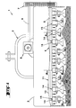
- FIGs 1 and 2 an agricultural machine (1) for grinding intended to be linked to a motor vehicle (not shown) by means of a coupling device (2).
- the agricultural grinding machine (1) comprises, according to the example shown, a cover (3) housing a rotor (4) which is intended to rotate about an axis of rotation (5) at least substantially horizontal and transverse to the advance direction (6) at work.
- the rotor (4) is rotated by a secondary transmission (7) which receives the movement of a transmission primary (8) by means of a drive shaft (9).
- Primary transmission (8) is driven by the motor vehicle by means of a jointed drive shaft universal (not shown).
- the rotor (4) has a central core (11) which is, according to this example of shown embodiment, a tube (12) of cylindrical shape. On this tube (12) are arranged grinding tools (13) which are, according to the example shown, tools grinding (13) commonly called hammer knives. Each tool grinding (13) is linked to the tube (12) of the central core (11) by means of a link (14).
- This connecting device (14) comprises a means (15) allowing said audit grinding tool (13) to occupy several working positions so as to describe, during the rotation of the rotor (4), trajectories of different radii corresponding at different work levels.
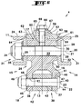
- This means (15) comprises, as shown on Figures 3 to 6, an intermediate support (16) linked, around one (17) of these ends (17, 18), to the central core (11) of the rotor (4) by means of a first articulation (20) of the cylindrical type with axis (21) at least substantially parallel to the axis of rotation (5) of the rotor (4).
- the furthest from the central core (11) of the rotor (4) is linked to a grinding tool (13) using a second articulation (22) also of the cylindrical type of axis (23) at least substantially parallel to the axis (21) of the first articulation (20).
- the first articulation (20) has two wings (24, 25) fixed radially to the tube (12) of the central core (11). These wings (24, 25) forms a yoke (26) in which the end (17) of the support is mounted intermediate (16) by means of a first bolt (28) passing on the one hand the two wings (24, 25) by means of respective holes (29), and on the other hand the end (17) of said intermediate support (16) by means of an orifice (30) provided for this purpose.
- Each wing (24, 25) has a recess (31), in the recess (31) of the wing (25) is housed the head (32) of the screw (33) of the first bolt (28) and in the other recess (31) of the wing (24) is housed the nut (34) of said bolt (28) and a washer blocking (35).
- a washer blocking (35) allows, when working the machine agricultural (1) grinding, protect the head (32) and the nut (34) of the first bolt (28) projections of the ground material, which advantageously allows keep the initial shapes and dimensions of the first bolt (28) in order to facilitate possible disassembly of the latter to replace the support intermediate (16) for example.
- the head (32) of the screw (33) is square, and is stopped in rotation at means of the wing (25) which has for this purpose an adequate shape.
- the second articulation (22) also has two wings (37, 38) forming a yoke (39) forming part of the intermediate support (16).
- this yoke (39) is mounted the grinding tool (13) by means of a second bolt (40) passing through the two wings (37, 38) on the one hand by means of respective holes (41), and on the other hand the upper end (42) of the grinding tool (13) by means of a orifice (43) provided for this purpose.
- the head (44) of the screw (45) belonging to the second bolt (40) is square in shape, and is stopped in rotation by means of a stop (46) provided on the outer part of the wing (37).
- This judgment (46) has a substantially flat surface (47) on which is intended to come abut at least part of the head (44) of the screw (45) when the latter tends to turn.
- the intermediate support (16) includes means for reinforcement intended to stiffen it.
- the intermediate support (16) is provided with a rib (50) located on the one hand, at least substantially in the plane of section VI-VI, transversely between the two wings (37, 38) of the yoke (39), and extending on the other hand from the first articulation (20) towards the second articulation (22).
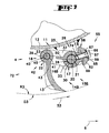
- each position (51, 52, 54) of the intermediate support (16) corresponds to a working level of the grinding tool (13).
- the grinding tool (13) describes, during the rotation of the rotor (4), different ray paths (R1, R2, R3) corresponding respectively at the radial position (51), at the first angular position (52) and at the second angular position (54).
- the grinding tool (13) sweeps, during rotation of the rotor (4), a circular surface of diameter (D1).
- the first and the second articulation (20, 22) respectively authorize a pivoting of the intermediate support (16) relative to the rotor (4) and the tool grinding (13) relative to said intermediate support (16).
- Such a design allows the intermediate support (16) and the grinding tool (13) to extend, when of the rotation of the rotor (4), at least substantially radially to said rotor (4), this which gives the means to the grinding tool (13) to sweep a circular surface of relatively large diameter (D1), so as to grind plants and residues plants located relatively distant from the central core (11) of the rotor (4).
- the grinding tool (13) has a large clearance because it can retract around the first joint (20) and around the second articulation (22) when it strikes a possible obstacle.
- the grinding tool (13) scans, during from the rotation of the rotor (4), a circular surface of diameter (D2).
- the second articulation (22) allows a pivoting of the grinding tool (13) relative to the intermediate support (16), while the first joint (20) is condemned using a means of blocking (55) fixing said intermediate support (16) on the central core (11) of the rotor (4).
- the locking means (55) comprises a locking screw (57) passing through on the one hand a member (58), fixed relative to said central core (11), by means of a hole (59) provided for this purpose, and screwed in other leaves in a first threaded hole (60) provided in the intermediate support (16).
- this first threaded hole (60) is made in a first bulge (61) located at the end (17) of the intermediate support (16).
- the member (58) is formed by a support piece (62) comprising, at each end of two opposite sides, a chamfer (63) by means of which it comes center and lean on complementary surfaces (64) provided on the wings (24, 25) of the yoke (26).
- the support piece (62) additionally has a surface plane (65) on which the head (66) of the locking screw (57) bears through a locking washer (67).
- the grinding tool (13) scans, during from the rotation of the rotor (4), a circular surface of diameter (D3).
- the second articulation (22) allows pivoting of the grinding tool (13), relative to the intermediate support (16), while the first articulation (20) is locked using the locking means (55), such as previously described.
- the locking screw (57) is screwed into a second threaded hole (70) implanted on the intermediate support (16), said threaded hole (70) corresponding to the second angular position (54).
- This second threaded hole (70) is produced in a second bulge (71) similar and adjacent to the first bulge (61).
- This second bulge (71) is located, as shown in Figures 4 and 5, between the tube (12) and the first bulge (61).
- intermediate support (16), according to this first embodiment, is symmetrical with respect to the plane passing through the first and the second joint (20, 22).
- the grinding tool extends, during work, at least substantially radially to the rotor (4).
- FIG. 7 shows a second embodiment of the device binding according to the present inventive idea.
- This connection device (14B) comprises a number of elements which have been described previously. These elements will therefore keep the same tag number and will not be rewritten. he also has a number of elements that are comparable to elements of the connecting device (14). These items will be affected the same reference number that these comparable elements of the connecting device (14) followed of the letter B. They will only be described if necessary.
- the connecting device (14B) is, on the whole, similar to the connecting device link (14). The difference is that only one position is provided angular (72) of the intermediate support (16B). For this purpose, the intermediate support (16B) has a single bulge (73) in which a threaded hole is provided (74).
- a blocking means comprising a locking screw passing through the intermediate support by means of a hole provided for this purpose and coming to be screwed into a threaded hole in the central core of the rotor.
- a blocking means comprising a locking pin crossing on the one hand the two wings of the first articulation by means of two holes located at least substantially one opposite of the other, and secondly the intermediate support by means of at least one hole provided on the latter which is placed at least substantially opposite the two holes of the wings cited above.
- the connecting device (14; 14B) to link other types of tools with the central core (11) of the rotor (4), such as for example mowing, chopping tools, etc.
Landscapes
- Life Sciences & Earth Sciences (AREA)
- Environmental Sciences (AREA)
- Crushing And Pulverization Processes (AREA)
- Crushing And Grinding (AREA)
- Harvester Elements (AREA)
Claims (8)
- Vorrichtung zur Verbindung eines Zerkleinerungswerkzeugs (13) mit einem mittleren Steg (11) eines Rotors (4) einer Landmaschine (1) zur Zerkleinerung von Pflanzengut, der sich um eine zumindest im wesentlichen horizontale und sich quer zur Fahrtrichtung (6) im Betrieb erstreckende Drehachse (5) dreht, wobei die Verbindungsvorrichtung ein Mittel (15; 15B) aufweist, das es dem Zerkleinerungswerkzeug (13) gestattet, mehrere Arbeitsstellungen einzunehmen, so daß es bei der Drehung des Rotors (4) verschiedenen Arbeitshöhen entsprechende Bahnen mit unterschiedlichen Radien beschreibt, dadurch gekennzeichnet, daß das Mittel (15; 15B)aufweist.einen Zwischenträger (16; 16B), mit dem das Zerkleinerungswerkzeug (13) verbunden ist und der seinerseits mittels eines eine zur Drehachse (5) des Rotors (4) zumindest im wesentlichen parallel verlaufende Achse (21) aufweisenden ersten Gelenks (20) mit einem mittleren Steg (11) des Rotors (4) verbunden werden soll, undein Sperrmittel (55), das das erste Gelenk (20) so sperren soll, daß der Zwischenträger (16; 16B) in mindestens einer von einer radialen Stellung (51) entfernten Winkelstellung (52, 54) an dem mittleren Steg (11) des Rotors (4) befestigt wird,
- Verbindungsvorrichtung nach Anspruch 1, dadurch gekennzeichnet, daß der Zwischenträger (16; 16B) mittels eines eine zur Achse (21) des ersten Gelenks (20) zumindest im wesentlichen parallel verlaufende Achse (23) aufweisenden zweiten Gelenks (22) mit dem Zerkleinerungswerkzeug (13) verbunden ist.
- Verbindungsvorrichtung nach Anspruch 1 oder 2, dadurch gekennzeichnet, daß die Winkelstellung(en) (52, 54) bezüglich der Drehrichtung (53) des Rotors (4) hinter der radialen Stellung (51) verläuft bzw. verlaufen.
- Verbindungsvorrichtung nach irgend einem der Ansprüche 1 bis 3, dadurch gekennzeichnet, daß das Sperrmittel (55) eine Sicherungsschraube (57) enthält, die einerseits den mittleren Steg (11) des Rotors (4) oder ein bezüglich des mittleren Stegs (11) festgelegtes Element (58) durchqueren und andererseits in mindestens ein Gewindeloch (60, 70; 74) des Zwischenträgers (16; 16B) geschraubt werden soll, oder umgekehrt.
- Verbindungsvorrichtung nach Anspruch 4, dadurch gekennzeichnet, daß der Zwischenträger (16; 16B) in einem dem mittleren Steg (11) des Rotors (4) entsprechenden Bügel (26) angebracht werden soll, und daß das Element (58) durch ein Stützteil (62) gebildet wird, das an den beiden Schenkeln (24, 25) des Bügels (26) zur Anlage kommen soll, wobei die Sicherungsschraube (57) dieses Stützteil (62) durchqueren und in ein in dem Zwischenträger (16; 16B) vorgesehenes Gewindeloch (60, 70; 74) geschraubt werden soll.
- Verbindungsvorrichtung nach Anspruch 5, dadurch gekennzeichnet, daß das Stützteil (62) und die Schenkel (24, 25) komplementäre Flächen (63, 64) aufweisen, die es zwischen den Schenkeln (24, 25) zentrieren sollen.
- Vorrichtung nach irgend einem der Ansprüche 1 bis 6, dadurch gekennzeichnet, daß der Zwischenträger (16, 16B) einen Bügel (39) aufweist, in dem das Zerkleinerungswerkzeug (13) angebracht ist.
- Landmaschine zur Zerkleinerung von Pflanzengut mit einem sich um eine zumindest im wesentlichen horizontale und sich quer zur Fahrtrichtung (6) im Betrieb erstreckende Drehachse (5) drehenden Rotor (4), der einen mittleren Steg (11) und jeweils mittels einer Verbindungsvorrichtung mit dem mittleren Steg (11) verbundene Zerkleinerungswerkzeuge (13) aufweist, dadurch gekennzeichnet, daß es sich mindestens bei bestimmten der Verbindungsvorrichtungen um Verbindungsvorrichtungen nach irgend einem der Ansprüche 1 bis 7 handelt.
Applications Claiming Priority (2)
| Application Number | Priority Date | Filing Date | Title |
|---|---|---|---|
| FR9507114 | 1995-06-12 | ||
| FR9507114A FR2734986B1 (fr) | 1995-06-12 | 1995-06-12 | Dispositif de liaison d'un outil de broyage a l'ame centrale d'un rotor. machine agricole de broyage de vegetaux equipee d'un tel dispositif |
Publications (2)
| Publication Number | Publication Date |
|---|---|
| EP0748582A1 EP0748582A1 (de) | 1996-12-18 |
| EP0748582B1 true EP0748582B1 (de) | 2000-10-04 |
Family
ID=9480011
Family Applications (1)
| Application Number | Title | Priority Date | Filing Date |
|---|---|---|---|
| EP19960440047 Expired - Lifetime EP0748582B1 (de) | 1995-06-12 | 1996-06-07 | Vorrichtung zur Verbindung eines Häckslerwerkzeugs mit einem Rotor; landwirtschaftliche Häckselmaschine versehen mit einer solchen Vorrichtung |
Country Status (4)
| Country | Link |
|---|---|
| EP (1) | EP0748582B1 (de) |
| DE (1) | DE69610526T2 (de) |
| ES (1) | ES2151647T3 (de) |
| FR (1) | FR2734986B1 (de) |
Families Citing this family (3)
| Publication number | Priority date | Publication date | Assignee | Title |
|---|---|---|---|---|
| DE10146773A1 (de) * | 2001-09-22 | 2003-04-17 | Deere & Co | Befestigungsanordnung zur Befestigung von Schlägeln an einem Rotor eines Strohhäckslers |
| DE10161714A1 (de) * | 2001-12-15 | 2003-06-18 | Deere & Co | Befestigungsanordnung zur Befestigung eines Schlägels an einem Rotor eines Strohhäckslers |
| DE102004019213A1 (de) * | 2004-04-21 | 2005-11-17 | Maschinenfabrik Bermatingen Gmbh & Co | Ballenpresse |
Family Cites Families (6)
| Publication number | Priority date | Publication date | Assignee | Title |
|---|---|---|---|---|
| FR633647A (fr) * | 1927-05-02 | 1928-02-01 | Machine à <<démultiplier>> les betteraves ensemencées ou autres plantes | |
| DE1204872B (de) * | 1964-03-28 | 1965-11-11 | John Deere Lanz Ag | Rotor fuer Trommelhaecksler mit am Messertraeger angeordneten Messerleisten |
| US3373548A (en) * | 1964-12-11 | 1968-03-19 | Deere & Co | Rotor for cutting, chopping, etc. |
| NL7413312A (nl) * | 1974-10-10 | 1976-04-13 | Lely Nv C Van Der | Grondbewerkingsmachine. |
| US3993143A (en) * | 1974-10-22 | 1976-11-23 | Moreland Jr John W | Turf reconditioning apparatus and method |
| US4060961A (en) * | 1976-02-23 | 1977-12-06 | Hesston Corporation | Crop harvesting rotor |
-
1995
- 1995-06-12 FR FR9507114A patent/FR2734986B1/fr not_active Expired - Fee Related
-
1996
- 1996-06-07 DE DE1996610526 patent/DE69610526T2/de not_active Expired - Fee Related
- 1996-06-07 ES ES96440047T patent/ES2151647T3/es not_active Expired - Lifetime
- 1996-06-07 EP EP19960440047 patent/EP0748582B1/de not_active Expired - Lifetime
Also Published As
| Publication number | Publication date |
|---|---|
| ES2151647T3 (es) | 2001-01-01 |
| DE69610526T2 (de) | 2001-05-31 |
| FR2734986B1 (fr) | 1997-08-22 |
| EP0748582A1 (de) | 1996-12-18 |
| FR2734986A1 (fr) | 1996-12-13 |
| DE69610526D1 (de) | 2000-11-09 |
Similar Documents
| Publication | Publication Date | Title |
|---|---|---|
| EP0239515B1 (de) | Rotationsmähwerk | |
| EP0809928B1 (de) | Mähmaschine | |
| EP1163832B1 (de) | Böschungsmäher | |
| EP1110442B1 (de) | Schneideelement für Mäher | |
| EP0748582B1 (de) | Vorrichtung zur Verbindung eines Häckslerwerkzeugs mit einem Rotor; landwirtschaftliche Häckselmaschine versehen mit einer solchen Vorrichtung | |
| EP0910940B1 (de) | Landwirtschaftmaschine | |
| EP0470990B1 (de) | Drehende Scheibe für einen Scheibenpflug | |
| EP1222844B1 (de) | Werkzeug für Rotorfräse | |
| EP3251489B1 (de) | Balkenmäher mit rotierenden mähmesserscheiben | |
| FR2733115A1 (fr) | Dispositif debroussailleur-broyeur de vegetaux | |
| EP0520918A1 (de) | Landwirtschaftliche Bodenbearbeitungsmaschine mit einem Rotor welcher sich quer zur Arbeitsrichtung erstreckt und mit verbesserten Reinigungswerkzeugen versehen ist | |
| CA3160243C (fr) | Dispositif de fauchage ou de broyage | |
| EP0200664B2 (de) | Kombinierte Landmaschine bestehend aus einer Bodenbearbeitungsmaschine und einer Walze | |
| FR2487157A1 (fr) | Berceau pour le montage d'un outil, notamment pour le travail de la terre, et instruments aratoires comprenant un tel berceau | |
| FR2668023A1 (fr) | Machine agricole de travail du sol comportant un rotor qui s'etend obliquement par rapport a la direction d'avance au travail. | |
| EP1147698B1 (de) | Bodenbearbeitungsgeräte | |
| EP0346255B1 (de) | Bodenbearbeitungsmaschine mit Scharen und einem Rotor | |
| FR2577103A1 (fr) | Procede et machine de decompactage de sol | |
| FR3106951A1 (fr) | Motobineuse | |
| FR3013179A1 (fr) | Outil manuel de jardinage de type sarcleuse | |
| EP4338568A1 (de) | An einem bodenbearbeitungsmaschinenrahmen anschliessbares pflanzenschneidmodul und bodenbearbeitungsmaschine mit mindestens einem schneidmodul | |
| FR2881916A1 (fr) | Broyeur a axe horizontal ayant une bonne uniformite de broyage | |
| EP0511276A1 (de) | Wendekörper. | |
| FR2613176A1 (fr) | Machine agricole de travail du sol | |
| FR2684845A1 (fr) | Outil de debrousaillement. |
Legal Events
| Date | Code | Title | Description |
|---|---|---|---|
| PUAI | Public reference made under article 153(3) epc to a published international application that has entered the european phase |
Free format text: ORIGINAL CODE: 0009012 |
|
| AK | Designated contracting states |
Kind code of ref document: A1 Designated state(s): DE ES FR GB IT NL |
|
| 17P | Request for examination filed |
Effective date: 19970523 |
|
| 17Q | First examination report despatched |
Effective date: 19990422 |
|
| GRAG | Despatch of communication of intention to grant |
Free format text: ORIGINAL CODE: EPIDOS AGRA |
|
| GRAG | Despatch of communication of intention to grant |
Free format text: ORIGINAL CODE: EPIDOS AGRA |
|
| GRAG | Despatch of communication of intention to grant |
Free format text: ORIGINAL CODE: EPIDOS AGRA |
|
| GRAH | Despatch of communication of intention to grant a patent |
Free format text: ORIGINAL CODE: EPIDOS IGRA |
|
| RIC1 | Information provided on ipc code assigned before grant |
Free format text: 7A 01D 34/00 A |
|
| GRAH | Despatch of communication of intention to grant a patent |
Free format text: ORIGINAL CODE: EPIDOS IGRA |
|
| GRAA | (expected) grant |
Free format text: ORIGINAL CODE: 0009210 |
|
| AK | Designated contracting states |
Kind code of ref document: B1 Designated state(s): DE ES FR GB IT NL |
|
| REF | Corresponds to: |
Ref document number: 69610526 Country of ref document: DE Date of ref document: 20001109 |
|
| ITF | It: translation for a ep patent filed | ||
| GBT | Gb: translation of ep patent filed (gb section 77(6)(a)/1977) |
Effective date: 20001116 |
|
| REG | Reference to a national code |
Ref country code: ES Ref legal event code: FG2A Ref document number: 2151647 Country of ref document: ES Kind code of ref document: T3 |
|
| PLBE | No opposition filed within time limit |
Free format text: ORIGINAL CODE: 0009261 |
|
| STAA | Information on the status of an ep patent application or granted ep patent |
Free format text: STATUS: NO OPPOSITION FILED WITHIN TIME LIMIT |
|
| 26N | No opposition filed | ||
| REG | Reference to a national code |
Ref country code: GB Ref legal event code: IF02 |
|
| PGFP | Annual fee paid to national office [announced via postgrant information from national office to epo] |
Ref country code: NL Payment date: 20090526 Year of fee payment: 14 Ref country code: ES Payment date: 20090609 Year of fee payment: 14 |
|
| PGFP | Annual fee paid to national office [announced via postgrant information from national office to epo] |
Ref country code: IT Payment date: 20090527 Year of fee payment: 14 |
|
| PGFP | Annual fee paid to national office [announced via postgrant information from national office to epo] |
Ref country code: FR Payment date: 20090630 Year of fee payment: 14 |
|
| PGFP | Annual fee paid to national office [announced via postgrant information from national office to epo] |
Ref country code: GB Payment date: 20090526 Year of fee payment: 14 Ref country code: DE Payment date: 20090703 Year of fee payment: 14 |
|
| REG | Reference to a national code |
Ref country code: NL Ref legal event code: V1 Effective date: 20110101 |
|
| GBPC | Gb: european patent ceased through non-payment of renewal fee |
Effective date: 20100607 |
|
| REG | Reference to a national code |
Ref country code: FR Ref legal event code: ST Effective date: 20110228 |
|
| PG25 | Lapsed in a contracting state [announced via postgrant information from national office to epo] |
Ref country code: IT Free format text: LAPSE BECAUSE OF NON-PAYMENT OF DUE FEES Effective date: 20100607 |
|
| PG25 | Lapsed in a contracting state [announced via postgrant information from national office to epo] |
Ref country code: DE Free format text: LAPSE BECAUSE OF NON-PAYMENT OF DUE FEES Effective date: 20110101 |
|
| PG25 | Lapsed in a contracting state [announced via postgrant information from national office to epo] |
Ref country code: NL Free format text: LAPSE BECAUSE OF NON-PAYMENT OF DUE FEES Effective date: 20110101 Ref country code: FR Free format text: LAPSE BECAUSE OF NON-PAYMENT OF DUE FEES Effective date: 20100630 |
|
| REG | Reference to a national code |
Ref country code: ES Ref legal event code: FD2A Effective date: 20110715 |
|
| PG25 | Lapsed in a contracting state [announced via postgrant information from national office to epo] |
Ref country code: ES Free format text: LAPSE BECAUSE OF NON-PAYMENT OF DUE FEES Effective date: 20110705 Ref country code: GB Free format text: LAPSE BECAUSE OF NON-PAYMENT OF DUE FEES Effective date: 20100607 |
|
| PG25 | Lapsed in a contracting state [announced via postgrant information from national office to epo] |
Ref country code: ES Free format text: LAPSE BECAUSE OF NON-PAYMENT OF DUE FEES Effective date: 20100608 |