EP0748662B1 - Verfahren zur Steuerung einer Rohrbiegemaschine - Google Patents
Verfahren zur Steuerung einer Rohrbiegemaschine Download PDFInfo
- Publication number
- EP0748662B1 EP0748662B1 EP96109222A EP96109222A EP0748662B1 EP 0748662 B1 EP0748662 B1 EP 0748662B1 EP 96109222 A EP96109222 A EP 96109222A EP 96109222 A EP96109222 A EP 96109222A EP 0748662 B1 EP0748662 B1 EP 0748662B1
- Authority
- EP
- European Patent Office
- Prior art keywords
- bending
- pipe
- actual value
- pressures
- cylinder
- Prior art date
- Legal status (The legal status is an assumption and is not a legal conclusion. Google has not performed a legal analysis and makes no representation as to the accuracy of the status listed.)
- Expired - Lifetime
Links
Images
Classifications
-
- B—PERFORMING OPERATIONS; TRANSPORTING
- B21—MECHANICAL METAL-WORKING WITHOUT ESSENTIALLY REMOVING MATERIAL; PUNCHING METAL
- B21D—WORKING OR PROCESSING OF SHEET METAL OR METAL TUBES, RODS OR PROFILES WITHOUT ESSENTIALLY REMOVING MATERIAL; PUNCHING METAL
- B21D7/00—Bending rods, profiles, or tubes
- B21D7/02—Bending rods, profiles, or tubes over a stationary forming member; by use of a swinging forming member or abutment
- B21D7/024—Bending rods, profiles, or tubes over a stationary forming member; by use of a swinging forming member or abutment by a swinging forming member
- B21D7/025—Bending rods, profiles, or tubes over a stationary forming member; by use of a swinging forming member or abutment by a swinging forming member and pulling or pushing the ends of the work
Definitions
- the invention relates to a method for controlling a Pipe bending machine and a pipe bending machine.
- DE 23 04 838 C2 describes a pipe bending process where the angle of rotation of the bending template and the Position of the slide rail can be determined. Corresponding the difference between the upsetting speed and the peripheral speed of the bending template an actual value is determined, which with a corresponding Setpoint value of the speed differences compared becomes.
- the comparison result is a servo valve fed one of the two hydraulic drives influenced. There is mutual coordination of feed speed and bending speed, that are equal to each other or to a certain one Ratio can be set.
- the invention has for its object a control method specify with which it is possible to use pipes with to bend gently with high accuracy and dimensional accuracy.
- the method according to the invention provides force control for the feed force with which the slide rail is advanced will, before. With this force control a Setpoint value of the feed force depending on the Angle of rotation of the bending template and the actual value the feed force becomes according to the setpoint regulated. According to the programmed course of the The setpoint is dependent on the current bending angle the feed force of the slide rail changed.
- the System is particularly suitable for thick-walled pipes and especially for pressure bending technology, where the unbent Pipe section in the direction during the bending process is pressed on the bending template, as well as for Extreme areas. As a result of the special pressure control the flow of force within the tube walls is influenced in a targeted manner. Variations in the material, its homogeneity and strength only affect the end product very low.
- control method according to the invention are therefore minor Wall thickness rejuvenation, low ovality and less Tool wear.
- One consequence of this is the possibility the reduction in pipe wall thickness, and thus a material saving, with the same strength of the finished pipe.
- They are also suitable according to the method bent tubes excellent for a subsequent Hydroforming, where there is high uniformity of the starting product arrives.
- the actual value of the feed force is thereby preferred determined that the pressures in the cylinder on both sides of the piston can be detected and from the pressures below Taking into account the sizes of the two piston surfaces the actual value of the feed force is determined. For this are only pressure sensors on the hydraulic cylinder required for the slide rail feed. Alternatively there is the possibility of a force sensor in to install the slide rail feed, however the stability of the slide rail feed is reduced.
- the pressures in the cylinder are expediently increased both sides of the piston changed in opposite directions to each other. This means that if the Feed pressure the back pressure is reduced. Thereby there is the possibility of the maximum pump pressure for to take full advantage of the feed.
- the method according to the invention does not necessarily have to be for a tube bending process from start to finish be performed. There is also the possibility the bending process partly according to the synchronous process and only in the critical areas with the invention Process, i.e. through force control.
- the invention further relates to a pipe bending machine.
- a device for recording the actual value the feed force applied by the cylinder provided and there is a controller that the Actual value of the feed force according to a setpoint readjusted depending on a setpoint generator from that of the position transmitter of the bending template supplied bending angle is generated.
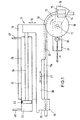
- the pipe bending machine shown schematically in Fig. 1 has one on a machine table (not shown) rotatably mounted bending template 10.
- the with a vertical axis of rotation 11 arranged bending template 10 has essentially the shape of a cylindrical body, a bending groove 12 is formed on the peripheral surface thereof which is the cross section of the pipe to be bent 13 takes up about half.
- a counter jaw 14 is attached with one Clamping jaw 15 cooperates to jointly pipe 13 to grasp and clamp for the bending process.
- the clamping jaw 15 is attached to a swivel arm 16, which is pivotable about an axis, which with the axis of rotation 11 of the bending template 10 coincides.
- the clamping jaw 15 is radial on this swivel arm 16 movable to clamp or release the pipe.
- the unbent portion 13a of the tube 13 is one Pressing device 17 supported.
- the pressing device has a carriage 18 which in the direction of the double arrow 19 transversely to the pipe section 13 is movable.
- the carriage 18 carries a lower carriage 20, which is longitudinal to the unbent Pipe section 13a, that is in the direction of the double arrow 21, is movable, and a cylinder 22 for moving of the lower carriage 20.
- the cylinder 22 is on the Carriage 18 fixed and in it is the piston 23 movable, the piston rod 24 on the lower slide 20 attacks to move it.
- the cylinder 22 has a working chamber 25 and a return stroke chamber 26, which are separated by the piston 23.
- a position transmitter 30 is arranged on the bending template 10.
- the position transmitter 30 has, for example a rotary encoder on which the rotational position of the Bending template 10 indicates.
- the bending template 10 is rotated by a (hydraulic) drive 31.
- a slide rail 32 which of the the side facing away from the bending template against the pipe 13 presses and the unbent pipe section 13a at Supports the bending process. Furthermore is on the lower carriage 20 a thrust element 35 attached to the rear Part of the unbent pipe section 13a attacks.
- the push element 35 can have a jaw 36, to clamp the pipe section 13a firmly. It is so trained that it acts on the tube without sliding.
- the Thrust element 35 and the jaw 36 are for that Pressure bending required. If no pressure bending is applied the feed force is determined exclusively by the Transfer the slide rail 32 to the tube 13.
- the straight tube is between the clamping jaw 15 and counter jaw 14 clamped. Then it will be the bending template 10 according to a predetermined program rotated, pulling the tube around the bending template and at the same time the straight pipe section 13a is moved forward. During the bending process the lower slide 20 is parallel to the pipe section 13a advanced by the hydraulic cylinder 22.
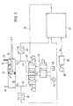
- Position A connects valve 42 to lines 40 and 41 with a switching valve 43, which with a pump 44 and a sump 45 is connected and between one Pass position and a blocking position switched can be.
- the position B of the valve 42 is used for the fast feed and position C for the return stroke piston 23.
- a pressure transducer 46 is connected to line 40, which generates a current signal that corresponds to the hydraulic Pressure in line 40 corresponds.
- a pressure transducer 47 is connected, the one Current signal generated that the hydraulic pressure in the Line 41 corresponds.
- the outputs of the two pressure transducers 46 and 47 are connected to a controller 48, to the control line 39 the control signal for the Differential valve 42 delivers.
- the controller 48 calculates from the pressures in chambers 25 and 26 and the sizes of the two piston surfaces A1 and A2 the actual value Fi Feeding force acting on the slide 20.
- the controller 48 is also provided with a setpoint generator 49 connected, which is a target value Fs of the feed force delivers to the controller 48.
- This setpoint Fs the Feed force varies depending on the angle of rotation ⁇ of the bending template 10, the position transmitter 30th is delivered.
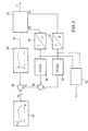
- Fig. 3 shows the control scheme.
- the setpoint generator 49 contains several curves representing the setpoint Fs of the feed force depending on the angle of rotation ⁇ of the bending template Specify 10. Can on the setpoint generator the desired curve can be selected. Further can the value ⁇ for the start on the setpoint generator and the end of pipe machining can be entered.
- the Setpoint generator 49 then delivers depending on ⁇ the associated setpoint Fs, of which in a Subtractor 50 the actual value Fi is subtracted.
- the Subtraction result is fed to the controller 48 which for example a PID controller.
- This controller delivers via the control line 39 a control signal to the Control path 51, which here consists of differential valve 42 and the cylinder 22 (Fig. 2).
- the pressure P1 in the line 40 and the pressure P2 in the Line 41 are the respective converter 46 and 47th fed.
- the output signal of converter 46 is shown in a multiplier 52 multiplied by a value, which corresponds to the area A1 of the piston 23.
- the output signal of the converter 47 is in a multiplier 53 multiplied by a value equal to the size of the Surface A2 of the piston 23 corresponds.
- the multiplier 52 thus forms the product P1 x A1 and the multiplier 53 forms the product P2 x A2. Any of these products is a measure of one of the two opposing forces interact with each other on the piston 23.
- a subtractor 54 subtracts the two products from each other, so that the actual value Fi of the feed force arises. This actual value is in the subtractor 50 from the Setpoint Fs subtracted to the input signal for the Form controller 48.
- the output signals of the two converters 46 and 47 are an error evaluation 55 fed an alarm signal generated or stops the pipe bending machine if the pressures P1 and P2 show abnormalities. It can also e.g. Total failures of the sensor are shown.
Landscapes
- Engineering & Computer Science (AREA)
- Mechanical Engineering (AREA)
- Bending Of Plates, Rods, And Pipes (AREA)
Description
- Fig. 1
- eine schematische Darstellung einer Rohrbiegemaschine in Draufsicht,
- Fig. 2
- ein Blockschaltbild der Regelung des Gleitschienenvorschubes und
- Fig. 3
- das Regelschema des Gleitschienenvorschubes.
Claims (6)
- Verfahren zur Steuerung einer Rohrbiegemaschine, die eine drehbare Biegeschablone (10), eine das Rohr (13) gegen die Biegeschablone (10) drückende Spannbacke (15) und eine an dem ungebogenen Rohrabschnitt (13a) angreifende, von einem hydraulischen Zylinder (22) vorschiebbare Gleitschiene (32) aufweist von der eine Vorschubkraft auf das Rohr übertragen wird, bei welchem der jeweilige Biegewinkel (α) der Biegeschablone (10) gemessen wird,
dadurch gekennzeichnet, daßaus einem Sollwert-Generator (49) entsprechend dem Biegewinkel (α) ein Sollwert (Fs) für die Vorschubkraft ausgegeben wird,der Istwert (Fi) der Vorschubkraft ermittelt wird,und die Drücke (P1,P2) im Zylinder (22) so verändert werden, daß der Istwert (Fi) dem Sollwert (Fs) der Vorschubkraft folgt. - Verfahren nach Anspruch 1, dadurch gekennzeichnet, daß der Istwert (Fi) der Vorschubkraft dadurch ermittelt wird, daß die Drücke (P1,P2) im Zylinder (22) auf beiden Seiten des Kolbens (23) erfaßt werden und aus den Drücken unter Berücksichtigung der Größen der beiden Kolbenflächen (A1,A2) der Istwert (Fi) der Vorschubkraft bestimmt wird.
- Verfahren nach Anspruch 1 oder 2, dadurch gekennzeichnet, daß die Drücke (P1,P2) im Zylinder (22) auf beiden Seiten des Kolbens (23) gegenläufig zueinander verändert werden.
- Rohrbiegemaschine zum Biegen eines Rohres (10), mit einer von einem Antrieb (33) drehbaren Biegeschablone (10), einer das Rohr (13) gegen die Biegeschablone (10) drückenden Spannbacke (15), einer an dem ungebogenen Rohrabschnitt (13a) angreifenden, von einem hydraulischen Zylinder (22) angetriebenen Gleitschiene (32), einem Positionsgeber (30) zur Ermittlung der Drehposition der Biegeschablone (10) und einer Einrichtung, die den Druck im Zylinder (22) für den Vorschub der Gleitschiene (32) in Abhängigkeit von dem Signal des Positionsgebers (30) verändert,
dadurch gekennzeichnet,
daß eine Einrichtung (46,47,52,53) zur Erfassung des Istwertes (Fi) der von dem Zylinder (22) aufgebrachten Vorschubkraft (F) vorgesehen ist, und daß ein Regler (48) den Istwert (Fi) der Vorschubkraft entsprechend einem Sollwert (Fs) nachregelt, der von einem Sollwert-Generator (49) in Abhängigkeit von dem vom Positionsgeber (30) gelieferten Biegewinkel (α) erzeugt wird. - Rohrbiegemaschine nach Anspruch 4, dadurch gekennzeichnet, daß die Einrichtung (46,47,52,53) zur Erfassung des Istwertes (Fi) der Vorschubkraft (F) zwei Drucksensoren (46,47) aufweist, die die Drücke (P1,P2) zu beiden Seiten des Kolbens (23) erfassen.
- Rohrbiegemaschine nach Anspruch 4 oder 5, dadurch gekennzeichnet, daß der Regler (48) ein Regelventil (42) mit stetiger Drosselkennlinie steuert, welches die Drücke (P1,P2) zu beiden Seiten des Kolbens (23) gegenläufig zueinander verändert.
Applications Claiming Priority (2)
| Application Number | Priority Date | Filing Date | Title |
|---|---|---|---|
| DE19522062A DE19522062A1 (de) | 1995-06-17 | 1995-06-17 | Verfahren zur Steuerung einer Rohrbiegemaschine |
| DE19522062 | 1995-06-17 |
Publications (2)
| Publication Number | Publication Date |
|---|---|
| EP0748662A1 EP0748662A1 (de) | 1996-12-18 |
| EP0748662B1 true EP0748662B1 (de) | 2000-03-22 |
Family
ID=7764608
Family Applications (1)
| Application Number | Title | Priority Date | Filing Date |
|---|---|---|---|
| EP96109222A Expired - Lifetime EP0748662B1 (de) | 1995-06-17 | 1996-06-08 | Verfahren zur Steuerung einer Rohrbiegemaschine |
Country Status (4)
| Country | Link |
|---|---|
| US (1) | US5682781A (de) |
| EP (1) | EP0748662B1 (de) |
| CA (1) | CA2178985C (de) |
| DE (2) | DE19522062A1 (de) |
Families Citing this family (8)
| Publication number | Priority date | Publication date | Assignee | Title |
|---|---|---|---|---|
| US5836188A (en) * | 1997-04-09 | 1998-11-17 | Pilot Industries, Inc. | Method and apparatus for bending an elongated member to a target angle |
| US5907896A (en) * | 1997-09-10 | 1999-06-01 | Tseng; Shao-Chien | Method for bending forging artistic metallic pipes |
| US6014884A (en) * | 1997-12-11 | 2000-01-18 | Proprietary Technology, Inc. | Method of bending tubing |
| US6253595B1 (en) * | 1999-09-21 | 2001-07-03 | Crc-Evans Pipeline International, Inc. | Automated pipe bending machine |
| US7765841B2 (en) * | 2006-02-16 | 2010-08-03 | Oes, Inc. | Quality analysis of tube bending processes including mandrel fault detection |
| US7302823B1 (en) * | 2006-07-06 | 2007-12-04 | Crc-Evans Pipeline International, Inc. | Gauge for pipe bending machine |
| CN102773319A (zh) * | 2012-08-07 | 2012-11-14 | 张家港市华舜机械制造有限公司 | 一种弯管机辅推装置 |
| CN106040807B (zh) * | 2016-08-10 | 2017-12-15 | 上虞市荣迪机械有限公司 | 铜管折弯机 |
Family Cites Families (8)
| Publication number | Priority date | Publication date | Assignee | Title |
|---|---|---|---|---|
| US3303683A (en) * | 1963-11-27 | 1967-02-14 | Pines Engineering Co Inc | Press die assembly for bending machines |
| DE2304838C2 (de) * | 1973-02-01 | 1982-08-19 | Deutsche Babcock Ag, 4200 Oberhausen | Rohrbiegevorrichtung |
| US4201073A (en) * | 1978-03-17 | 1980-05-06 | Eaton-Leonard Corporation | Reaction bender for pipe |
| JPS58205620A (ja) * | 1982-05-26 | 1983-11-30 | Hitachi Ltd | パイプ曲げ加工装置 |
| US4747283A (en) * | 1987-08-24 | 1988-05-31 | Teledyne Industries | Boosted drive for pressure die of a tube bender |
| US4970885A (en) * | 1989-06-12 | 1990-11-20 | Vickers, Incorporated | Tube bending apparatus |
| DE4129478A1 (de) * | 1991-09-05 | 1993-03-11 | Schwarze Rigobert | Verfahren zur steuerung einer rohrbiegemaschine |
| US5343725A (en) * | 1993-07-07 | 1994-09-06 | Eagle Precision Technologies Inc. | Tube bending apparatus and method |
-
1995
- 1995-06-17 DE DE19522062A patent/DE19522062A1/de not_active Withdrawn
-
1996
- 1996-06-08 EP EP96109222A patent/EP0748662B1/de not_active Expired - Lifetime
- 1996-06-08 DE DE59604728T patent/DE59604728D1/de not_active Expired - Fee Related
- 1996-06-14 CA CA002178985A patent/CA2178985C/en not_active Expired - Fee Related
- 1996-06-17 US US08/664,666 patent/US5682781A/en not_active Expired - Lifetime
Also Published As
| Publication number | Publication date |
|---|---|
| CA2178985C (en) | 2006-10-03 |
| DE19522062A1 (de) | 1996-12-19 |
| EP0748662A1 (de) | 1996-12-18 |
| CA2178985A1 (en) | 1996-12-18 |
| US5682781A (en) | 1997-11-04 |
| DE59604728D1 (de) | 2000-04-27 |
Similar Documents
| Publication | Publication Date | Title |
|---|---|---|
| EP0530452B1 (de) | Verfahren zur Steuerung einer Rohrbiegemaschine | |
| EP0633076B1 (de) | Rohrbiegevorrichtung- und verfahren | |
| DE2559696C2 (de) | Vorrichtung zum Warmbiegen von Metallrohren | |
| EP2144720B1 (de) | Verfahren und vorrichtung zum profilbiegen | |
| DE69604330T2 (de) | Verbesserungen in oder in Verband mit einer Einrichtung zum Kreuzen oder axialen Verschieben von Walzen | |
| EP3524421B1 (de) | Presse und verfahren zu deren betrieb | |
| DE69404820T2 (de) | Rohrbiegevorrichtung | |
| WO1991017004A1 (de) | Verfahren zur steuerung der umlauf-bahnbewegungen der drückrolle einer drückmaschine und drückmaschine zur durchführung des verfahrens | |
| EP0748662B1 (de) | Verfahren zur Steuerung einer Rohrbiegemaschine | |
| EP0761334B1 (de) | Strangbiegemaschine | |
| DE2856525C2 (de) | Steuereinrichtung in einer Vorrichtung zur Herstellung langer Stäbe oder Stangen | |
| EP1782896B1 (de) | Verfahren zum Umformen eines Werkstückes und Walzmaschine | |
| DE69401594T2 (de) | Adaptives biegen | |
| DE69325367T2 (de) | Verfahren zum strangpressen von metall- oder kunststoffprofilen und vorrichtung dafür | |
| EP0757925A1 (de) | Verfahren zur Steuerung einer Rohrbiegemaschine | |
| DE69001326T2 (de) | Elektrohydraulisches system. | |
| DE2346797A1 (de) | Automatisches richtverfahren und richtpresse dafuer mit einer richtstelle | |
| DE2942810C2 (de) | Vorrichtung zur Regelung der im Walzgut übertragenen Kraft zwischen zwei aufeinanderfolgenden Gerüsten einer kontinuierlichen Walzstraße | |
| DE2304838C2 (de) | Rohrbiegevorrichtung | |
| DE102005047285B4 (de) | Verfahren zur Führung einer mit einer SPS gesteuerten und mit einer Profiltemperaturregelung und Pressgeschwindigkeitsregelung ausgestatteten Strangpresse für Metalle | |
| DE3404807C2 (de) | ||
| DE3923358A1 (de) | Verfahren und presse zur herstellung kaltgeformter rohrfoermiger koerper | |
| AT402479B (de) | Verfahren und vorrichtung zum biegen von hohlprofil-werkstücken | |
| DE10329898B4 (de) | Verfahren und Vorrichtung zum Umformen von Blechplatinen | |
| DE19722523A1 (de) | Verfahren und Vorrichtung zur hydraulisch-elektrischen Spaltregelung |
Legal Events
| Date | Code | Title | Description |
|---|---|---|---|
| PUAI | Public reference made under article 153(3) epc to a published international application that has entered the european phase |
Free format text: ORIGINAL CODE: 0009012 |
|
| AK | Designated contracting states |
Kind code of ref document: A1 Designated state(s): CH DE FR GB IT LI NL SE |
|
| 17P | Request for examination filed |
Effective date: 19970605 |
|
| 17Q | First examination report despatched |
Effective date: 19971124 |
|
| GRAG | Despatch of communication of intention to grant |
Free format text: ORIGINAL CODE: EPIDOS AGRA |
|
| GRAG | Despatch of communication of intention to grant |
Free format text: ORIGINAL CODE: EPIDOS AGRA |
|
| GRAH | Despatch of communication of intention to grant a patent |
Free format text: ORIGINAL CODE: EPIDOS IGRA |
|
| GRAH | Despatch of communication of intention to grant a patent |
Free format text: ORIGINAL CODE: EPIDOS IGRA |
|
| GRAA | (expected) grant |
Free format text: ORIGINAL CODE: 0009210 |
|
| AK | Designated contracting states |
Kind code of ref document: B1 Designated state(s): CH DE FR GB IT LI NL SE |
|
| REG | Reference to a national code |
Ref country code: CH Ref legal event code: NV Representative=s name: TROESCH SCHEIDEGGER WERNER AG Ref country code: CH Ref legal event code: EP |
|
| ITF | It: translation for a ep patent filed | ||
| GBT | Gb: translation of ep patent filed (gb section 77(6)(a)/1977) |
Effective date: 20000324 |
|
| REF | Corresponds to: |
Ref document number: 59604728 Country of ref document: DE Date of ref document: 20000427 |
|
| ET | Fr: translation filed | ||
| PLBE | No opposition filed within time limit |
Free format text: ORIGINAL CODE: 0009261 |
|
| STAA | Information on the status of an ep patent application or granted ep patent |
Free format text: STATUS: NO OPPOSITION FILED WITHIN TIME LIMIT |
|
| 26N | No opposition filed | ||
| REG | Reference to a national code |
Ref country code: GB Ref legal event code: IF02 |
|
| PGFP | Annual fee paid to national office [announced via postgrant information from national office to epo] |
Ref country code: NL Payment date: 20090624 Year of fee payment: 14 |
|
| PGFP | Annual fee paid to national office [announced via postgrant information from national office to epo] |
Ref country code: SE Payment date: 20090623 Year of fee payment: 14 |
|
| PGFP | Annual fee paid to national office [announced via postgrant information from national office to epo] |
Ref country code: FR Payment date: 20090618 Year of fee payment: 14 Ref country code: CH Payment date: 20090624 Year of fee payment: 14 |
|
| PGFP | Annual fee paid to national office [announced via postgrant information from national office to epo] |
Ref country code: GB Payment date: 20090623 Year of fee payment: 14 Ref country code: DE Payment date: 20090826 Year of fee payment: 14 |
|
| PGFP | Annual fee paid to national office [announced via postgrant information from national office to epo] |
Ref country code: IT Payment date: 20090626 Year of fee payment: 14 |
|
| REG | Reference to a national code |
Ref country code: NL Ref legal event code: V1 Effective date: 20110101 |
|
| REG | Reference to a national code |
Ref country code: CH Ref legal event code: PL |
|
| EUG | Se: european patent has lapsed | ||
| GBPC | Gb: european patent ceased through non-payment of renewal fee |
Effective date: 20100608 |
|
| REG | Reference to a national code |
Ref country code: FR Ref legal event code: ST Effective date: 20110228 |
|
| PG25 | Lapsed in a contracting state [announced via postgrant information from national office to epo] |
Ref country code: IT Free format text: LAPSE BECAUSE OF NON-PAYMENT OF DUE FEES Effective date: 20100608 |
|
| PG25 | Lapsed in a contracting state [announced via postgrant information from national office to epo] |
Ref country code: DE Free format text: LAPSE BECAUSE OF NON-PAYMENT OF DUE FEES Effective date: 20110101 Ref country code: CH Free format text: LAPSE BECAUSE OF NON-PAYMENT OF DUE FEES Effective date: 20100630 Ref country code: LI Free format text: LAPSE BECAUSE OF NON-PAYMENT OF DUE FEES Effective date: 20100630 |
|
| PG25 | Lapsed in a contracting state [announced via postgrant information from national office to epo] |
Ref country code: FR Free format text: LAPSE BECAUSE OF NON-PAYMENT OF DUE FEES Effective date: 20100630 Ref country code: NL Free format text: LAPSE BECAUSE OF NON-PAYMENT OF DUE FEES Effective date: 20110101 |
|
| PG25 | Lapsed in a contracting state [announced via postgrant information from national office to epo] |
Ref country code: GB Free format text: LAPSE BECAUSE OF NON-PAYMENT OF DUE FEES Effective date: 20100608 |
|
| PG25 | Lapsed in a contracting state [announced via postgrant information from national office to epo] |
Ref country code: SE Free format text: LAPSE BECAUSE OF NON-PAYMENT OF DUE FEES Effective date: 20100609 |