EP0748665B1 - Ein Spannglied für hin- und hergehendes Sägeblatt - Google Patents
Ein Spannglied für hin- und hergehendes Sägeblatt Download PDFInfo
- Publication number
- EP0748665B1 EP0748665B1 EP96304268A EP96304268A EP0748665B1 EP 0748665 B1 EP0748665 B1 EP 0748665B1 EP 96304268 A EP96304268 A EP 96304268A EP 96304268 A EP96304268 A EP 96304268A EP 0748665 B1 EP0748665 B1 EP 0748665B1
- Authority
- EP
- European Patent Office
- Prior art keywords
- release lever
- saw blade
- reciprocating saw
- saw
- drive shaft
- Prior art date
- Legal status (The legal status is an assumption and is not a legal conclusion. Google has not performed a legal analysis and makes no representation as to the accuracy of the status listed.)
- Expired - Lifetime
Links
- 230000008901 benefit Effects 0.000 claims description 4
- 238000013459 approach Methods 0.000 claims description 3
- 238000006073 displacement reaction Methods 0.000 claims description 2
- 238000010276 construction Methods 0.000 description 10
- 230000009471 action Effects 0.000 description 3
- 239000000463 material Substances 0.000 description 3
- 230000004048 modification Effects 0.000 description 3
- 238000012986 modification Methods 0.000 description 3
- 238000009434 installation Methods 0.000 description 2
- 238000004519 manufacturing process Methods 0.000 description 2
- 230000007246 mechanism Effects 0.000 description 2
- 229910052751 metal Inorganic materials 0.000 description 2
- 239000002184 metal Substances 0.000 description 2
- 229910000760 Hardened steel Inorganic materials 0.000 description 1
- FYYHWMGAXLPEAU-UHFFFAOYSA-N Magnesium Chemical compound [Mg] FYYHWMGAXLPEAU-UHFFFAOYSA-N 0.000 description 1
- 229910000831 Steel Inorganic materials 0.000 description 1
- 239000004411 aluminium Substances 0.000 description 1
- 229910052782 aluminium Inorganic materials 0.000 description 1
- XAGFODPZIPBFFR-UHFFFAOYSA-N aluminium Chemical compound [Al] XAGFODPZIPBFFR-UHFFFAOYSA-N 0.000 description 1
- 230000003466 anti-cipated effect Effects 0.000 description 1
- 230000008859 change Effects 0.000 description 1
- 230000008030 elimination Effects 0.000 description 1
- 238000003379 elimination reaction Methods 0.000 description 1
- 230000006872 improvement Effects 0.000 description 1
- 239000011777 magnesium Substances 0.000 description 1
- 229910052749 magnesium Inorganic materials 0.000 description 1
- 230000002028 premature Effects 0.000 description 1
- 238000000926 separation method Methods 0.000 description 1
- 239000010959 steel Substances 0.000 description 1
Images


Classifications
-
- B—PERFORMING OPERATIONS; TRANSPORTING
- B23—MACHINE TOOLS; METAL-WORKING NOT OTHERWISE PROVIDED FOR
- B23D—PLANING; SLOTTING; SHEARING; BROACHING; SAWING; FILING; SCRAPING; LIKE OPERATIONS FOR WORKING METAL BY REMOVING MATERIAL, NOT OTHERWISE PROVIDED FOR
- B23D51/00—Sawing machines or sawing devices working with straight blades, characterised only by constructional features of particular parts; Carrying or attaching means for tools, covered by this subclass, which are connected to a carrier at both ends
- B23D51/08—Sawing machines or sawing devices working with straight blades, characterised only by constructional features of particular parts; Carrying or attaching means for tools, covered by this subclass, which are connected to a carrier at both ends of devices for mounting straight saw blades or other tools
- B23D51/10—Sawing machines or sawing devices working with straight blades, characterised only by constructional features of particular parts; Carrying or attaching means for tools, covered by this subclass, which are connected to a carrier at both ends of devices for mounting straight saw blades or other tools for hand-held or hand-operated devices
-
- Y—GENERAL TAGGING OF NEW TECHNOLOGICAL DEVELOPMENTS; GENERAL TAGGING OF CROSS-SECTIONAL TECHNOLOGIES SPANNING OVER SEVERAL SECTIONS OF THE IPC; TECHNICAL SUBJECTS COVERED BY FORMER USPC CROSS-REFERENCE ART COLLECTIONS [XRACs] AND DIGESTS
- Y10—TECHNICAL SUBJECTS COVERED BY FORMER USPC
- Y10T—TECHNICAL SUBJECTS COVERED BY FORMER US CLASSIFICATION
- Y10T279/00—Chucks or sockets
- Y10T279/17—Socket type
- Y10T279/17761—Side detent
- Y10T279/17786—Spring
Definitions
- the present invention relates in general to power tools.
- the present invention relates to a power reciprocating saw with a saw blade clamping arrangement, having a saw blade mounted for reciprocating cutting motion, as defined in the preamble of claim 1.
- Power reciprocating saws include jigsaws and other reciprocating saws often referred to in the trade as "recip" saws. These saws incorporate reciprocating shafts for driving generally linear saw blades along an orbital or rectilinear path so as to provide a cutting action.
- the saw blades used with such power tools are attached to the reciprocating drive shafts through a blade holder having a slot for receiving the saw blade and a set screw which is received in a hole in the blade.
- the blade is clamped in place relative to the reciprocating drive shaft through tightening of the set screw. While this manner of saw blade attachment has proven to be generally satisfactory and commercially successful, it is not without inherent disadvantages.
- each of the devices shown in these patents represents an attempt to overcome one or more of the disadvantages associated with conventional set screw attachment of a saw blade to a reciprocating drive shaft, including but not limited to the disadvantages discussed above.
- all of these devices are subject to further refinement and improvement.
- many of the devices including U.S. Patent No. 5,322,302, which discloses the closest prior art according to the preamble of claim 1, disadvantageously require two-handed operation.
- most of the devices shown in these patents are complicated and expensive to manufacture and assemble as a result of a construction including many separate parts.
- operation of many of the prior devices requires application of force which is often significant for securing the saw blade in place and loosening of the blade for separation from the drive shaft. Achieving a sufficient force often requires the use of a wrench or other tool.
- Other disadvantages associated with these prior devices include an inability to cooperate with conventionally shaped saw blades.
- a power reciprocating saw comprises a housing, a drive shaft mounted to the reciprocating saw for reciprocating motion relative to the housing and a clamping arrangement for releasably connecting a saw blade to the drive shaft for reciprocating cutting movement.
- the clamping arrangement includes a biasing member and an actuation member.
- the biasing member is interconnected with the drive shaft for movement therewith and functions to bias the saw blade against the drive shaft for establishing an operative connection between the saw blade and the drive shaft.
- the actuation member is attached to the reciprocating saw, and is characterised in that the actuation member is longitudinally fixed with respect to the housing and the actuation member is moveable between a first stable position spaced apart from the biasing member and a second stable position engaging the biasing member.
- the present invention provides an improved saw blade clamping arrangement for a power tool. While shown in a saw blade clamping arrangement specifically adapted for a reciprocating saw, those skilled in the art will appreciate that the invention is not so limited in scope. In this regard, the teachings of the present invention will be understood to be readily adaptable for use with any power tool incorporating a reciprocating cutting members (e.g., reciprocating saws, jig saws, various surgical saws and culinary knives, etc.).
- a reciprocating cutting members e.g., reciprocating saws, jig saws, various surgical saws and culinary knives, etc.
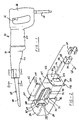
- FIG. 1 an exemplary power tool embodying the teachings of the present invention is illustrated in Figure 1 as a power reciprocating saw and is identified generally at reference numeral 10.
- power reciprocating saw 10 is powered by a motor (not shown) that is actuated by a trigger switch 12.
- the delivery of electrical energy to the motor through a power cord (partially shown at 14) is controlled by trigger switch 12.
- power tool 10 is shown to include a handle portion 16 which carries trigger switch 12.
- Power tool 10 is also shown to include a housing 18 that includes a centrally located motor housing portion 20 and a forwardly located gear case housing portion 22.
- gear case housing portion 22 is formed to include a front face 24 having a generally rectangular aperture 26 which defines the opening of a longitudinally extending drive shaft channel 28.
- Power tool 10 further includes a drive shaft 30 partially extending within drive shaft channel 28 and operatively connected with a drive mechanism (not shown) housed within gear case housing portion 22. This interconnection between the drive mechanism and drive shaft 30 can be in any manner well known in the art.
- Drive shaft 30 is mounted for reciprocating motion generally along the longitudinal axis defined by power tool 10.
- the housing 18 includes first and second forwardly extending sidewall members 32 and 34 interconnected with gear case housing portion 22.
- first and second forwardly extending side wall members 32 and 34 are integrally formed with gear case housing 22 and are constructed of aluminium, magnesium or other suitable lightweight metal. The particular configuration and function of first and second forwardly extending sidewall members 32 and 34 will be described in detail below.
- Drive shaft 30 is adapted to cooperate with a cutting member such as a saw blade 38 for driving the saw blade 38 back and forth in a cutting motion along a rectilinear path.
- reciprocating drive shaft 30 is formed to include a transversely extending aperture 40 for receiving a drive pin 42 (shown in Figure 7).
- An interference fit retains drive pin 42 within aperture 40.
- the saw blade construction shown in Figures 1 and 7 conventionally includes a forwardly located cutting portion 44 integrally formed with a rearwardly located mounting portion 46.
- an aperture 48 formed in mounting portion 46 of saw blade 38 receives drive pin 42 when saw blade 38 is mounted to reciprocating drive shaft 30.
- the exposed end of drive pin 42 extends from a first side wall 52 (shown in Figure 8) of reciprocating shaft 30 in a dimension approximately equivalent to the thickness of saw blade 38.
- Power tool 10 of the present invention further includes a clamping arrangement 56 for releasably maintaining saw blade 38 in operative connection with reciprocating drive shaft 30.
- Clamping arrangement 56 is shown throughout the drawings to include a clamp support member 58, a biasing member 60, and a actuation member 62. The remainder of this detail description will be primarily directed to the construction and operation of clamping arrangement 56 which is the focus of the present invention.
- clamp support member 58 is illustrated as a separate element which is adapted to be interconnected with reciprocating drive shaft 30 for movement therewith.
- clamp support member 58 and drive shaft 30 may alternatively be integrally formed as a single component.
- Clamp support member 58 is unitarily constructed of a hardened steel or other suitable material. Interconnection between clamp support members 58 and drive shaft 30 is established through a roll pin 68 in interference fit engagement with a transversely extending aperture 70 passing through clamp support member 58 and a corresponding aperture 72 disposed in reciprocating drive shaft 30.
- Clamp support member 58 includes a main body portion 73 which partially defines a longitudinally extending channel 74 sized to receive reciprocating drive shaft 30. More particularly, the longitudinal channel 74 is defined by an inner wag 75 and by first and second opposing side walls 76 and 78 which each terminate at end walls 80 and 82, respectively. Inner wall 75 is concavely curved to receive a second side wall 79 of reciprocating drive shaft 30. In the preferred embodiment, a first side wall 52 of reciprocating drive shaft 30 is adapted to sit flush with end walls 80 and 82 (as shown in Figures 11 and 12). End walls 80 and 82 cooperate with first side wall 52 to provide a surface against which saw blade 38 is disposed when operatively connected with power tool 10.
- clamp support member 58 Adjacent an upper surface 86, clamp support member 58 is formed to integrally include an L-shaped flange 88 which partially defines a channel 90 for receiving an upper surface 94 of saw blade 38. Adjacent a lower surface 96, clamp support member 58 includes an outwardly extending portion 98 adapted to abut a lower surface 100 of saw blade 38. Upper surface 86 of clamp support member 59 includes a pair of spaced, upwardly extending flange portions 102 and 104. As will be appreciated below, flange portions 102 and 104 cooperate to limit longitudinal movement of biasing member 60. A second transversely extending channel 108 is partially defined between the main body portion 73 of clamp support member 58 and a downwardly extending portion 110 of a rear wall 112 of clamp support 58. Channel 108 is open along a bottom side.
- the biasing member of the present invention is preferably illustrated as a spring clamp member 60.
- Spring clamp member 60 is adapted to be directly carried by clamp support member 58 for movement with reciprocating drive shaft 30.
- Spring clamp member 60 is generally C-shaped and is integrally formed of a resilient metal or other suitable material to include a curvilinear central portion 120 and first and second ends 122 and 124.
- spring clamp member 60 is constructed of 1.27mm (.050 inch) steel.
- a side view of clamp spring member 60 is shown in Figure 6 in a substantially unloaded condition.
- An aperture 125 passes through central portion 120 which is adapted to accept an end of drive pin 42 when a saw blade is not in clamping arrangement 56.
- Clamp spring member 60 further includes generally linear upper and lower segments 126 and 128 integrally attached to opposite ends of curvilinear central portion 120. Upper and lower segments 126 and 128 are disposed generally transverse to curvilinear central portion 120 and cooperate with the curvilinear central portion 120 to partially define a longitudinally extending opening 130 for receiving a portion of clamp support member 58 and reciprocal drive shaft 30.
- Spring clamp member 60 is further shown to include a retaining portion 132 adjacent second end 124 which is adapted to be constrained within longitudinal channel 108 of clamp support member 58.
- Spring clamp member 60 further integrally includes a spring tab portion 136 adjacent first end 122 which extends upwardly relative to upper segment 126 and is angled slightly rearwards in the direction of curvilinear central portion 120. Spring tab portion 136 is free from direct constraint with respect to clamp support member 58.
- lower segment 128 of spring clamp member 60 When assembled and in clamping engagement with drive shaft 30 and saw blade 38, lower segment 128 of spring clamp member 60 is positioned adjacent bottom surface 96 of clamp support member 58. In an unloaded condition, upper segment 126 of spring clamp member 60 is arranged to be positioned substantially adjacent upper surface 86 of clamp support member 58. As discussed above, longitudinal translation of spring clamp member 60 is limited by flange portions 102 and 104 of clamp support member 58.
- Curvilinear central portion 120 includes a lower, outwardly curved segment 139 which accommodates saw blade 38 and an upper, outwardly curved segment 140. Curvilinear central portion 120 further includes an inwardly curved central portion 142 arranged to directly contact saw blade 38. It will be appreciated by those skilled in the art that the particular construction of spring clamp 60 is subject to modification without departing from the scope of the present invention. Any construction will be suitable which incorporates a portion for fixation to clamp support member 58, a portion for directly biasing saw blade 38 and a displaceable free end.
- clamp spring member 60 While in a clamping position such as that shown in Figure 11, clamp spring member 60 functions to exert a biasing force against saw blade 38 through contact of central portion 142 and saw blade 38.
- the biasing force serves to retain saw blade 38 in operative connection with reciprocation drive shaft 30 by preventing saw blade 38 from moving transversely with respect to drive shaft 30.
- clamping arrangement 56 of the present invention is able to accommodate saw blades of various configurations without modification.
- two alternative saw blade constructions suitable for use with clamping arrangement 56 are illustrated in Figures 9 and 10.
- a first alternative saw blade 38 includes a generally rectangular mounting portion 46 formed with an aperture 48 sized to receive drive pin 42.
- a second alternative saw blade 38 is shown to include an aperture 48 and a longitudinally extending slot 144. Any of a number of other known saw blade constructions may be releasably interconnected to drive shaft 30 through clamping arrangement 56 of the present invention.
- actuation member of the present invention is preferably illustrated as a release lever 62 operative to overcome the biasing force of spring clamp member 60 and thereby facilitate removal and replacement of saw blade 38.
- release lever 62 is mounted for pivotal movement between a first stable position or clamped position (shown in Figure 11) and a second stable position or unclamped position (shown in Figure 12).
- first stable position or clamped position shown in Figure 11
- second stable position or unclamped position shown in Figure 12
- release lever 62 when release lever 62 is in its first stable position it is spaced apart from spring clamp member 60 permitting release lever 62 to remain longitudinally fixed with respect to housing 18.
- release lever 62 remains relatively stationary as reciprocating drive shaft 30 operates, thereby reducing the weight translated back and forth by drive shaft 30 and also reducing attendant vibration forces.
- power tool 10 further includes an end plate 150 interconnected with first and second forwardly extending sidewall members 32 and 34.
- end plate 150 is generally planar and has a configuration similar to front face 24 of gear case housing 22.
- End plate 150 includes an aperture 152 through which saw blade 38 is permitted to pass.
- end plate 150 is attached to first and second forwardly extending side wall members 32 and 34 by a plurality of threaded fasteners 154 adapted to pass through four apertures 156 provided in the end plate.
- Fasteners 154 are adapted to engage threaded holes 158 located in boss portions 160 on each of the forwardly extending side walls members 32 and 34.
- boss portions 160 are located along the free ends of first and second forwardly extending side wall members 32 and 34. It will be appreciated by those skilled in the art that the end plate 150 can be alternatively attached to forwardly extending side wall members 32 and 34 in any of a number of other well known manners. In this regard, it is anticipated that end plate 150 could alternatively be welded to forwardly extending side walls members 32 and 34.
- Release lever 62 has a generally L-shaped cross section including a first log 170 and a second log 172.
- the longitudinal length of release lever 62 is sufficient to extend along the entire travel path of spring clamp member 60 as drive shaft 30 is reciprocated.
- a longitudinally extending aperture 174 passes through the length of release lever 62 at the junction of first and second legs 170 and 172 and is adapted to receive a pivot pin 176.
- Pivot pin 176 includes a first end 178 adapted to engage an aperture 180 formed in front face 24 and a second end 182 adapted to engage an aperture 184 located in end plate 150. Second end 182 is of a reduced diameter so as to prevent forward translation of pin 176.
- release lever 62 is formed to include a recess or pocket 188 configured to accommodate a torsion spring 190.
- Torsion spring 190 functions to bias release lever 62 towards its first stable position (as shown in Figure 11) and includes a central portion surrounding an adjacent portion of pivot pin 176.
- Torsion spring 190 also includes a fixed end 194 in engagement with a boss portion 196 of recess 188.
- Torsion spring 190 further includes a free end 198 adapted to engage a stop pin 200 extending from front face 24 of gear case housing 22. Stop pin extends into recess 180 to avoid interference with release lever 62.
- second forwardly extending wall member 34 is generally S-shaped in cross section and includes an upper segment 208 providing a stop surface 210 arranged to support release lever 62.
- Upper segment 208 serves to prevent further rotation of release lever 62 in a counterclockwise direction as shown in Figures 11 and 12.
- First leg 170 of release lever 62 transversely extends slightly beyond an upper vertical segment 212 of second forwardly extending wall member 34 so that the operator can grasp a free end 214 of first leg 170.
- First forwardly extending side wall member 32 is generally L-shaped in cross-section and is formed along the perimeter of a corresponding portion of front face 24 of gear case housing 22.
- An upper segment 216 of second forwardly extending side wall member 34 terminates at a stop surface 218 for engaging release lever 62 when release lever 62 is rotated to its second stable position (as shown in Figure 12).
- Second leg 172 of release lever 62 includes an engagement surface 222 adapted to contact spring tab portion 136 of spring, clamp member 60. As shown in Figure 12, clockwise rotation of release lever 62 about a longitudinal pivot defined by pivot pin 176 results in contact between engagement surface 216 of second log 172 and spring tab portion 136 of spring clamp member 60.
- the length of second leg 172 is significantly less than the length of first leg 170, thereby providing a mechanical advantage for overcoming the biasing force exerted by spring clamp member 60.
- pivot axis of release lever 62 defined by pivot pin 176 is disposed relative to engagement surface 222 of second leg 172 so as to provide an over-centered relationship therebetween.
- release lever 62 is rotated in a clockwise direction from its first stable position (shown in Figure 11) by manual urging of first leg 170 to overcome the biasing force of torsion spring 190.
- Initial clockwise rotation causes second leg 172 of release lever 62 to engage spring tab portion 136 of spring clamp member 62.
- release lever 62 serves to transversely displace spring tab portion 136 and to overcome the biasing force of spring clamp member 62 by elastically deforming the spring clamp member 60. More specifically, elastic displacement of spring tab portion 136 creates a gap 224 between curvilinear central portion 120 of spring clamp member 60 and saw blade 38.
- release lever 62 approaches its second stable position, the over-centered relation between engagement surface 222 of second leg 172 and the pivot axis defined by pivot pin 176 causes the biasing force of spring clamp member 60 to further urge release lever 62 in a clockwise direction against stop surface 218. At this point, release lever 62 will stay in its second stable position until urged in the direction of its first stable position. As a result, both of the operator hands are free for handling replacement of saw blade 38 or other necessary tasks.
- Saw blade 38 can now be removed from power tool 10 and a new blade can be inserted into gap 224 between spring clamp member 60 and reciprocating drive shaft 30.
- Upper edge 94 of saw blade 38 is located in channel 90 and aperture 48 is positioned over drive pin 42.
- Operating interconnection between saw blade 38 and reciprocating drive shaft 30 is established by manual urging of release lever 62 in a counterclockwise direction. Following initial counterclockwise movement of lever 62, the biasing force of spring clamp member 60 urges release lever 62 to its first stable position.
- the present invention has a number of advantages compared to prior known blade mounting arrangements for power tools, including those disclosed in the aforementioned patents. More particularly, the present invention provides a new and improved saw blade mounting arrangement for a power reciprocating saw which includes a release lever operative to permit quick and easy installation and removal of a saw blade.
- the release lever is pivotally mounted for movement between two stable positions. Further in the preferred embodiment, the release lever is not interconnected with the drive shaft for reciprocating movement therewith.
- the present invention provides a power reciprocating saw in which the saw blade can be mounted in place and detached using only a single hand.
- the present invention provides a saw blade mounting arrangement for a power reciprocating saw of simple construction which is relatively inexpensive to manufacture and assemble. Furthermore, the present invention provides a blade mounting arrangement which can accommodate conventional saw blades of various constructions and which can hold the saw blade in place without the use of set screws and without the need to employ any other form of a tool. Still yet, the present invention provides a blade mounting arrangement having a design which protects its components from excessive wear and premature failure.
Landscapes
- Engineering & Computer Science (AREA)
- Mechanical Engineering (AREA)
- Sawing (AREA)
Claims (20)
- Kraftgetriebene Säge (10) mit hin- und herbewegtem Sägeblatt aufweisend:dadurch gekennzeichnet, dass das Betätigungselement in Längsrichtung bezüglich dem Gehäuse befestigt und zwischen einer ersten stabilen Stellung im Abstand vom Vorspannelement und einer zweiten stabilen Stellung in Eingriff mit dem Vorspannelement bewegbar ist.ein Gehäuse (18),einen zur Hin- und Herbewegung bezüglich dem Gehäuse an der Säge befestigten Antriebsschaft (30),eine Klemmanordnung (56) zur lösbaren Verbindung eines Sägeblatts (38) mit dem Antriebsschaft zur hin- und hergerichteten Schneidbewegung, wobei die Klemmanordnung aufweist:a) ein mit dem Antriebsschaft zur Bewegung mit diesem verbundenes Vorspannelement (60), das das Sägeblatt gegen den Antriebsschaft vorspannt, um eine betriebsmäßige Verbindung zwischen Sägeblatt und Antriebsschaft auszubilden, undb) ein an der Säge angebrachtes Betätigungselement (62),
- Kraftgetriebene Säge mit hin- und herbewegtem Sägeblatt nach Anspruch 1, bei dem ein Klemmenstützelement (58) mit dem Antriebsschaft (10) verbunden und das Vorspannelement (60) am Klemmenstützelement (58) angebracht ist.
- Kraftgetriebene Säge mit hin- und herbewegtem Sägeblatt nach Anspruch 2, bei der das Vorspannelement (60) ein Klemmenfederelement (60) ist, das ein bezüglich dem Klemmenstützelement (58) festgelegtes erstes Ende (124, 132) aufweist.
- Kraftgetriebene Säge mit hin- und herbewegtem Sägeblatt nach Anspruch 3, bei der das Klemmenfederelement das Sägeblatt (38) direkt berührt, um auf dieses eine Vorspannkraft auszuüben, die das Sägeblatt in betriebsmäßiger Verbindung mit dem Antriebsschaft (30) hält.
- Kraftgetriebene Säge mit hin- und herbewegtem Sägeblatt nach Anspruch 4, bei der die vom Klemmenfederelement (60) auf das Sägeblatt (38) ausgeübte Vorspannkraft verhindert, dass sich das Sägeblatt (38) quer bezüglich dem Antriebsschaft (30) bewegt.
- Kraftgetriebene Säge mit hin- und herbewegtem Sägeblatt nach Anspruch 4 oder 5, bei der das Klemmenfederelement (60) einen gekrümmten Mittelbereich (120) mit einem zur direkten Berührung mit dem Sägeblatt (38) angeordneten, nach innen gekrümmten Bereich (142) aufweist.
- Kraftgetriebene Säge mit hin- und herbewegtem Sägeblatt nach einem der Ansprüche 3 bis 6, bei der das Betätigungselement (62) ein zur schwenkbaren Bewegung zwischen der ersten stabilen Stellung und der zweiten stabilen Stellung befestigter Freigabehebel (62) ist.
- Kraftgetriebene Säge mit hin- und herbewegtem Sägeblatt nach Anspruch 7, bei der die Schwenkbewegung des Freigabehebels (62) von der ersten stabilen Stellung in die zweite stabile Stellung im Uhrzeigersinn erfolgt und bei der die Drehung des Freigabehebels (62) von der zweiten stabilen Stellung in die erste stabile Stellung im Gegenuhrzeigersinn erfolgt.
- Kraftgetriebene Säge mit hin- und herbewegtem Sägeblatt nach Anspruch 7 oder 8, bei der der Freigabehebel um eine parallel zur und im Abstand von der Längsachse angeordnete Schwenkachse schwenkbar befestigt ist.
- Kraftgetriebene Säge mit hin- und herbewegtem Sägeblatt nach Anspruch 9, bei der der Freigabehebel (62) durch eine Torsionsfeder (190) im Gegenuhrzeigersinn in Richtung der ersten stabilen Stellung vorgespannt ist.
- Kraftgetriebene Säge mit hin- und herbewegtem Sägeblatt nach Anspruch 10, bei der das Gehäuse eine im Wesentlichen senkrecht zur Längsachse angeordnete vordere Fläche (24) hat und bei der die Schwenkachse durch einen Schwenkstift (176) gebildet ist, der ein sich in eine in der vorderen Fläche (24) vorgesehene Öffnung (180) erstreckendes erstes Ende (178) hat.
- Kraftgetriebene Säge mit hin- und herbewegtem Sägeblatt nach Anspruch 11, bei dem die Torsionsfeder (190)
ein festes Ende (194),
ein freies Ende (198) und
einen den Schwenkstift (176) umgebenden Mittelbereich aufweist, wobei das feste Ende (194) in Eingriff mit dem Freigabehebel (62) und das freie Ende (198) in Eingriff mit einem sich vom vorderen Ende (24) des Gehäuses erstreckenden Anschlagstift (200) steht. - Kraftgetriebene Säge mit hin- und herbewegtem Sägeblatt nach Anspruch 11 oder 12, bei der das Gehäuse ferner erste und zweite im Abstand voneinander angeordnete Wandbereiche (32, 34), die sich von der vorderen Fläche (24) nach vorn erstrecken, und eine Endplatte (150) aufweist, die an den ersten und zweiten im Abstand voneinander angeordneten Wandbereichen angebracht ist.
- Kraftgetriebene Säge mit hin- und herbewegtem Sägeblatt nach Anspruch 13, bei der der zweite Wandbereich (34) eine zur Abstützung des Freigabehebels (62) in der ersten stabilen Stellung und zur Verhinderung einer weiteren Drehung des Freigabehebels (62) im Gegenuhrzeigersinn dienende Anschlagfläche (210) aufweist.
- Kraftgetriebene Säge mit hin- und herbewegtem Sägeblatt nach Anspruch 13 oder 14, bei der die Drehung das Freigabehebels (62) im Uhrzeigersinn um den Schwenkstift (176) zum Querverlagern des Klemmenfederelements (60) dient, um die Vorspannkraft des Klemmenfederelements (60) durch dessen elastische Verformung zu überwinden.
- Kraftgetriebene Säge mit hin- und herbewegtem Sägeblatt nach Anspruch 15, bei der die Querverlagerung des Klemmenfederelements (60) einen Spalt (224) zwischen dem Klemmenfederelement (60) und dem Sägeblatt (38) ausbildet, um das Sägeblatt entfernen zu können.
- Kraftgetriebene Säge mit hin- und herbewegtem Sägeblatt nach Anspruch 15 oder 16, bei der der Freigabehebel (62) eine zur Berührung mit dem Klemmenfederelement (60) angepasste Eingriffsfläche (222) aufweist und bei der die Drehung des Freigabehebels (62) im Uhrzeigersinn um den Schwenkstift (176) zur Berührung zwischen Eingriffsfläche (222) und Klemmenfederelement (60) führt, um das Klemmenfederelement (60) quer zu verlagern, wobei der Schwenkstift (176) bezüglich der Eingriffsfläche (222) so angeordnet ist, dass sich eine gesperrte Endlage zwischen Schwenkstift (176) und Eingriffsfläche (222) ergibt, so dass die Vorspannkraft des Klemmenfederelements (60) den Freigabehebel (62) gegen den ersten Wandbereich (32) drückt, wenn sich der Freigabehebel (62) der zweiten stabilen Stellung annähert.
- Kraftgetriebene Säge mit hin- und herbewegtem Sägeblatt nach Anspruch 17, bei der der zweite Wandbereich eine Anschlagfläche (82) für den Eingriff des Freigabehebels (62) in der zweiten stabilen Stellung aufweist, um eine weitere Drehung des Freigabehebels (62) im Uhrzeigersinn zu verhindern.
- Kraftgetriebene Säge mit hin- und herbewegtem Sägeblatt nach Anspruch 17 oder 18, bei der der Freigabehebel (62) einen im Allgemeinen L-förmigen Querschnitt mit
einem ersten Arm (170),
einem zweiten Arm (172) und
einer sich in Längsrichtung erstreckenden Öffnung (174) hat, die sich im Schnittbereich von erstem und zweitem Arm (170, 172) durch die Länge des Freigabehebels (62) erstreckt, wobei die Öffnung (174) zur Aufnahme des Schwenkstifts (176) angepasst ist. - Kraftgetriebene Säge mit hin- und herbewegtem Sägeblatt nach Anspruch 19, bei der die Eingriffsfläche (222) auf dem zweiten Arm (172) vorgesehen und die Länge des zweiten Arms (172) wesentlich kleiner als die Länge des ersten Arms (170) ist, wodurch sich ein mechanischer Vorteil für das Überwinden der von dem Klemmenfederelement (60) ausgeübten Vorspannkraft ergibt.
Applications Claiming Priority (2)
| Application Number | Priority Date | Filing Date | Title |
|---|---|---|---|
| US08/504,050 US5647133A (en) | 1995-06-09 | 1995-06-09 | Saw blade clamping arrangement for a power tool |
| US504050 | 2000-02-14 |
Publications (2)
| Publication Number | Publication Date |
|---|---|
| EP0748665A1 EP0748665A1 (de) | 1996-12-18 |
| EP0748665B1 true EP0748665B1 (de) | 2003-03-19 |
Family
ID=24004650
Family Applications (1)
| Application Number | Title | Priority Date | Filing Date |
|---|---|---|---|
| EP96304268A Expired - Lifetime EP0748665B1 (de) | 1995-06-09 | 1996-06-07 | Ein Spannglied für hin- und hergehendes Sägeblatt |
Country Status (4)
| Country | Link |
|---|---|
| US (2) | US5647133A (de) |
| EP (1) | EP0748665B1 (de) |
| JP (1) | JP3810859B2 (de) |
| DE (1) | DE69626720T2 (de) |
Families Citing this family (38)
| Publication number | Priority date | Publication date | Assignee | Title |
|---|---|---|---|---|
| US6295736B1 (en) | 1995-06-09 | 2001-10-02 | Black & Decker Inc. | Blade ejection mechanism for a saw blade clamping arrangement of a power tool |
| US6944959B2 (en) * | 1995-06-09 | 2005-09-20 | Black & Decker Inc. | Clamping arrangement for receiving a saw blade in multiple orientations |
| US7325315B2 (en) * | 1995-06-09 | 2008-02-05 | Black & Decker Inc. | Clamping arrangement for receiving a saw blade in multiple orientations |
| GB9604463D0 (en) * | 1996-03-01 | 1996-05-01 | Black & Decker Inc | A saw blade clamp |
| DE69714651T2 (de) * | 1996-05-23 | 2003-03-13 | Black & Decker Inc., Newark | Sägeblattaufspannvorrichtung für ein motorisiertes Werkzeug |
| EP0882537B1 (de) * | 1997-06-05 | 2003-09-03 | Black & Decker Inc. | Sägemaschine mit hin- und hergehendem Sägeblatt und Sägeblattspannvorrichtung mit mehrfacher Sägeblattspannposition |
| US7127973B2 (en) * | 1998-02-09 | 2006-10-31 | Milwaukee Electric Tool Corporation | Reciprocating saw |
| USD408699S (en) | 1998-04-15 | 1999-04-27 | Black & Decker Inc. | Reciprocating saw |
| US6263979B1 (en) | 1998-07-24 | 2001-07-24 | The Black & Decker Corporation | Interchangeable implement system for power tools |
| JP3858529B2 (ja) * | 1998-10-23 | 2006-12-13 | 日立工機株式会社 | セーバソーのブレード着脱機構 |
| JP3542511B2 (ja) | 1998-12-24 | 2004-07-14 | 株式会社マキタ | 往復切断工具の刃具取り付け装置 |
| US6112420A (en) * | 1999-08-10 | 2000-09-05 | S-B Power Tool Company | Blade clamp for reciprocating saw |
| USD440849S1 (en) | 2000-03-09 | 2001-04-24 | Hitachi Koki Co., Ltd. | Portable electric saw |
| JP3995895B2 (ja) * | 2000-05-16 | 2007-10-24 | 株式会社マキタ | 往復動切断工具のブレード取り付け装置 |
| US7257900B2 (en) | 2002-01-02 | 2007-08-21 | Black & Decker Inc. | Canted saw blade |
| US6662698B2 (en) | 2002-01-02 | 2003-12-16 | Black & Decker Inc. | Saw blade clamp system |
| JP4166982B2 (ja) | 2002-01-15 | 2008-10-15 | 日立工機株式会社 | セーバソー |
| JP4244615B2 (ja) * | 2002-04-22 | 2009-03-25 | 日立工機株式会社 | 電動切断機 |
| US6755424B1 (en) | 2002-07-12 | 2004-06-29 | Scott A. Paulsen | Quick-Change tool attachment system for a reciprocating power unit |
| US7040023B2 (en) * | 2002-11-25 | 2006-05-09 | Eastway Fair Company Limited | Toolless blade holder for a reciprocating tool |
| USD525842S1 (en) * | 2003-09-23 | 2006-08-01 | Positec Power Tools (Suzhou) Co. Ltd. | Reciprocating saw |
| GB2407532A (en) * | 2003-10-28 | 2005-05-04 | Black & Decker Inc | Clamp assembly for removably mounting a working member |
| US7871080B2 (en) * | 2004-01-16 | 2011-01-18 | Robert Bosch Gmbh | Tool-less blade clamping apparatus for a reciprocating tool |
| US20050192585A1 (en) * | 2004-02-27 | 2005-09-01 | Medtronic, Inc. | Surgical saw collet with closed drive ring |
| USD523719S1 (en) * | 2004-04-05 | 2006-06-27 | Positec Power Tools (Suzhou) Co., Ltd. | Reciprocating saw |
| USD523310S1 (en) * | 2004-04-20 | 2006-06-20 | Black & Decker Inc. | Reciprocating saw |
| USD527597S1 (en) * | 2004-05-17 | 2006-09-05 | Positec Power Tools (Suzhou) Co., Ltd. | Reciprocating saw |
| JP4573637B2 (ja) * | 2004-12-02 | 2010-11-04 | 株式会社マキタ | 往復動式作業工具 |
| USD534778S1 (en) * | 2005-05-26 | 2007-01-09 | Choon Nang Electrical Appliance Mfy., Ltd. | Electric saw |
| US7437824B2 (en) * | 2005-06-27 | 2008-10-21 | Black & Decker Inc. | Adjustable shoe assembly for a reciprocating saw |
| USD551930S1 (en) * | 2006-04-10 | 2007-10-02 | Hitachi Koki Co., Ltd. | Reciprocating saw |
| US7984914B1 (en) * | 2006-06-06 | 2011-07-26 | Paulsen Scott A | Attachment system with a removable and replaceable tongue for use with a reciprocating driver |
| US8813372B2 (en) | 2007-09-14 | 2014-08-26 | Milwaukee Electric Tool Corporation | Blade clamp mechanism |
| US8230607B2 (en) | 2008-05-09 | 2012-07-31 | Milwaukee Electric Tool Corporation | Keyless blade clamp for a power tool |
| JP5921385B2 (ja) * | 2012-08-22 | 2016-05-24 | 株式会社マキタ | レシプロソー |
| US9097344B2 (en) * | 2012-09-28 | 2015-08-04 | Caterpillar Inc. | Automatic shift control system for a powertrain and method |
| DE102015218339A1 (de) * | 2015-09-24 | 2017-03-30 | Robert Bosch Gmbh | Handgeführte Hubsäge mit einer Verlaufskorrekturvorrichtung und Verfahren zur Verlaufskorrektur |
| JP7532227B2 (ja) | 2020-11-27 | 2024-08-13 | 株式会社マキタ | 往復動工具 |
Family Cites Families (30)
| Publication number | Priority date | Publication date | Assignee | Title |
|---|---|---|---|---|
| US1578475A (en) * | 1924-09-24 | 1926-03-30 | Sideman Reuben | Razor-blade sharpener |
| US2101362A (en) * | 1936-03-30 | 1937-12-07 | Armstrong Blum Mfg Co | Hacksaw |
| US2539574A (en) * | 1947-12-03 | 1951-01-30 | Fulmer Ray | Paring knife and razor blade stropper and sharpener |
| US3555678A (en) * | 1968-01-23 | 1971-01-19 | Gen Appliance Corp | Electric culinary device |
| US3542097A (en) * | 1968-05-02 | 1970-11-24 | Singer Co | Chuck assembly for sabre saws |
| US3823473A (en) * | 1970-11-09 | 1974-07-16 | S Hoffman | Blade attachment means for saber saw assembly |
| US4020555A (en) * | 1976-04-12 | 1977-05-03 | Pevrick Engineering Co., Inc. | Connecting mechanism for a saw blade |
| US4106181A (en) * | 1976-08-09 | 1978-08-15 | American Safety Equipment Corporation | Quick release mechanism for oscillating saw blade |
| US4243342A (en) * | 1979-07-27 | 1981-01-06 | J. I. Case Company | Snap fast fastener |
| US4648182A (en) * | 1979-08-01 | 1987-03-10 | Hoffman Simon J | Holder for saber saw blade |
| US4470196A (en) * | 1979-08-01 | 1984-09-11 | Hoffman Simon J | Holder for saber saw blade |
| US4441255A (en) * | 1979-08-01 | 1984-04-10 | Hoffman Simon J | Holder for saber saw blade |
| US4594781A (en) * | 1979-08-01 | 1986-06-17 | Hoffman Simon J | Holder for saber saw blade |
| US4294013A (en) * | 1980-02-25 | 1981-10-13 | Widder Corporation | Portable hacksaw |
| DE3245359A1 (de) * | 1982-12-08 | 1984-06-14 | Robert Bosch Gmbh, 7000 Stuttgart | Saege, insbesondere motorisch angetriebene handstichsaege |
| US4601477A (en) * | 1985-01-10 | 1986-07-22 | The Singer Company | Sabre saw blade clamp |
| DE3622761A1 (de) * | 1986-07-07 | 1988-01-21 | Bosch Gmbh Robert | Einspannvorrichtung fuer saegeblaetter |
| WO1989008524A1 (en) * | 1988-03-15 | 1989-09-21 | Robert Bosch Gmbh | Jigsaw |
| US5263972A (en) * | 1991-01-11 | 1993-11-23 | Stryker Corporation | Surgical handpiece chuck and blade |
| US5103565A (en) * | 1991-09-26 | 1992-04-14 | Skil Corporation | Blade holder for reciprocating saws |
| DE4138986A1 (de) * | 1991-11-27 | 1993-06-03 | Atlas Copco Elektrowerkzeuge | Spanneinrichtung fuer eine stichsaegemaschine |
| DE9202611U1 (de) * | 1992-02-28 | 1993-06-24 | Robert Bosch Gmbh, 7000 Stuttgart | Werkzeughalter |
| NL9201371A (nl) * | 1992-07-29 | 1994-02-16 | Emerson Electric Co | Zaagbladfixatie-inrichting. |
| US5458346A (en) * | 1993-12-28 | 1995-10-17 | Briggs; William L. | Keyless saw blade chuck |
| US5575071A (en) * | 1994-01-19 | 1996-11-19 | Porter-Cable Corporation | Toolless quickchange blade clamp for reciprocating saws |
| JP3212792B2 (ja) * | 1994-02-10 | 2001-09-25 | 株式会社マキタ | ジグソー |
| DE69510783T2 (de) * | 1994-04-12 | 1999-12-02 | Phillips, Alan G. | Schnellwechselsägeblattspannvorrichtung, bedienbar ohne zusätzliches werkzeug, für hin- und hergehende sägen |
| US5443276A (en) * | 1994-07-22 | 1995-08-22 | S-B Power Tool Company | Self-locking blade holder |
| JP2710565B2 (ja) * | 1994-09-29 | 1998-02-10 | リョービ株式会社 | 切断工具 |
| US6237231B1 (en) * | 1994-11-29 | 2001-05-29 | Milwaukee Electric Tool Corporation | Keyless clamp assembly for reciprocating tool |
-
1995
- 1995-06-09 US US08/504,050 patent/US5647133A/en not_active Expired - Lifetime
-
1996
- 1996-06-04 JP JP14186196A patent/JP3810859B2/ja not_active Expired - Fee Related
- 1996-06-07 DE DE69626720T patent/DE69626720T2/de not_active Expired - Lifetime
- 1996-06-07 EP EP96304268A patent/EP0748665B1/de not_active Expired - Lifetime
- 1996-11-05 US US08/744,023 patent/US5794352A/en not_active Expired - Lifetime
Also Published As
| Publication number | Publication date |
|---|---|
| JP3810859B2 (ja) | 2006-08-16 |
| US5647133A (en) | 1997-07-15 |
| DE69626720D1 (de) | 2003-04-24 |
| DE69626720T2 (de) | 2003-09-18 |
| JPH09109102A (ja) | 1997-04-28 |
| EP0748665A1 (de) | 1996-12-18 |
| US5794352A (en) | 1998-08-18 |
Similar Documents
| Publication | Publication Date | Title |
|---|---|---|
| EP0748665B1 (de) | Ein Spannglied für hin- und hergehendes Sägeblatt | |
| EP0949032B1 (de) | Sägeblattaufspannvorrichtung für ein motorisiertes Werkzeug | |
| US6009627A (en) | Saw blade clamping arrangement for a power tool | |
| US7003888B2 (en) | Clamping arrangement for receiving a saw blade | |
| US7325315B2 (en) | Clamping arrangement for receiving a saw blade in multiple orientations | |
| US6502317B2 (en) | Blade ejection mechanism for a saw blade clamping arrangement of a power tool | |
| CA2708545C (en) | Hand saw | |
| US3360021A (en) | Powered saw | |
| EP0810050B1 (de) | Sägeblattaufspannvorrichtung für ein motorisiertes Werkzeug | |
| US8327550B2 (en) | Blade clamp for reciprocating saw | |
| AU2006202824B2 (en) | Blade clamp for reciprotating saw |
Legal Events
| Date | Code | Title | Description |
|---|---|---|---|
| PUAI | Public reference made under article 153(3) epc to a published international application that has entered the european phase |
Free format text: ORIGINAL CODE: 0009012 |
|
| AK | Designated contracting states |
Kind code of ref document: A1 Designated state(s): DE GB IT |
|
| 17P | Request for examination filed |
Effective date: 19970526 |
|
| 17Q | First examination report despatched |
Effective date: 20010406 |
|
| GRAG | Despatch of communication of intention to grant |
Free format text: ORIGINAL CODE: EPIDOS AGRA |
|
| GRAG | Despatch of communication of intention to grant |
Free format text: ORIGINAL CODE: EPIDOS AGRA |
|
| GRAG | Despatch of communication of intention to grant |
Free format text: ORIGINAL CODE: EPIDOS AGRA |
|
| GRAH | Despatch of communication of intention to grant a patent |
Free format text: ORIGINAL CODE: EPIDOS IGRA |
|
| GRAH | Despatch of communication of intention to grant a patent |
Free format text: ORIGINAL CODE: EPIDOS IGRA |
|
| GRAA | (expected) grant |
Free format text: ORIGINAL CODE: 0009210 |
|
| AK | Designated contracting states |
Designated state(s): DE GB IT |
|
| REG | Reference to a national code |
Ref country code: GB Ref legal event code: FG4D |
|
| REF | Corresponds to: |
Ref document number: 69626720 Country of ref document: DE Date of ref document: 20030424 Kind code of ref document: P |
|
| PLBE | No opposition filed within time limit |
Free format text: ORIGINAL CODE: 0009261 |
|
| STAA | Information on the status of an ep patent application or granted ep patent |
Free format text: STATUS: NO OPPOSITION FILED WITHIN TIME LIMIT |
|
| 26N | No opposition filed |
Effective date: 20031222 |
|
| PGFP | Annual fee paid to national office [announced via postgrant information from national office to epo] |
Ref country code: IT Payment date: 20080626 Year of fee payment: 13 |
|
| PG25 | Lapsed in a contracting state [announced via postgrant information from national office to epo] |
Ref country code: IT Free format text: LAPSE BECAUSE OF NON-PAYMENT OF DUE FEES Effective date: 20090607 |
|
| PGFP | Annual fee paid to national office [announced via postgrant information from national office to epo] |
Ref country code: GB Payment date: 20110628 Year of fee payment: 16 |
|
| PGFP | Annual fee paid to national office [announced via postgrant information from national office to epo] |
Ref country code: DE Payment date: 20110629 Year of fee payment: 16 |
|
| GBPC | Gb: european patent ceased through non-payment of renewal fee |
Effective date: 20120607 |
|
| PG25 | Lapsed in a contracting state [announced via postgrant information from national office to epo] |
Ref country code: DE Free format text: LAPSE BECAUSE OF NON-PAYMENT OF DUE FEES Effective date: 20130101 Ref country code: GB Free format text: LAPSE BECAUSE OF NON-PAYMENT OF DUE FEES Effective date: 20120607 |
|
| REG | Reference to a national code |
Ref country code: DE Ref legal event code: R119 Ref document number: 69626720 Country of ref document: DE Effective date: 20130101 |