EP0748688A2 - Dispositif pour un système de retenu sous forme de fente - Google Patents
Dispositif pour un système de retenu sous forme de fente Download PDFInfo
- Publication number
- EP0748688A2 EP0748688A2 EP96109141A EP96109141A EP0748688A2 EP 0748688 A2 EP0748688 A2 EP 0748688A2 EP 96109141 A EP96109141 A EP 96109141A EP 96109141 A EP96109141 A EP 96109141A EP 0748688 A2 EP0748688 A2 EP 0748688A2
- Authority
- EP
- European Patent Office
- Prior art keywords
- slide
- slot
- plate
- rubber blanket
- blanket
- Prior art date
- Legal status (The legal status is an assumption and is not a legal conclusion. Google has not performed a legal analysis and makes no representation as to the accuracy of the status listed.)
- Granted
Links
Images
Classifications
-
- B—PERFORMING OPERATIONS; TRANSPORTING
- B41—PRINTING; LINING MACHINES; TYPEWRITERS; STAMPS
- B41F—PRINTING MACHINES OR PRESSES
- B41F30/00—Devices for attaching coverings or make-ready devices; Guiding devices for coverings
- B41F30/04—Devices for attaching coverings or make-ready devices; Guiding devices for coverings attaching to transfer cylinders
Definitions
- the invention relates to a device for a slit-shaped holding device for fastening plates, preferably rubber blankets, with bent ends in a narrow, axially extending slot of a cylinder of a rotary printing press.
- US-PS 25 25 003 a device for fastening a rubber blanket unit consisting of a rubber blanket and a carrier plate is described.
- the rubber blanket unit is provided with two folded ends, on each of which a folded leg of the carrier plate projects beyond the ends of the rubber blanket and the rubber blanket on the carrier plate ends in the region of a bevel delimiting the legs.
- These chamfered legs are inserted into a narrow, approx. 3.5 mm wide slot.
- a wedge is arranged between opposite side faces of the two legs, whereby one leg is pressed against one side face of the slot.
- the blanket unit is thus held frictionally in the slot by means of a holding device designed as a wedge.
- DE 35 38 308 C2 shows a device for winding of a blanket on a blanket cylinder of a web-fed rotary printing press.
- the blanket is connected to a dimensionally stable support plate to form a blanket unit.
- a bent leg of the carrier plate projects beyond the rubber blanket, while at a leading end, a bent leg is coated with the rubber blanket.
- DE-PS 19 60 635 an arrangement for fastening flexible printing plates on a plate cylinder is shown.
- the holding device described here consists of at least one axially extending slot made in a lateral surface of the plate cylinder. Folded plate ends are received from this slot.
- the invention has for its object a device for a device for attaching a plate, preferably a blanket unit, in to create a narrow, axially extending slot of a cylinder of a rotary printing press, which largely prevents dirt and ink from getting into the narrow slot.
- the advantages which can be achieved with the invention consist in particular in that a gap remaining between two ends of a rubber blanket is largely closed and nevertheless a fastening of rubber blanket plates is possible.
- the filler of the device according to the invention protects the free ends of the rubber blanket on the carrier plate against unnecessary wear.
- the already small vibrations, which are reduced by the narrow slot, are reduced even further as a result of the channel runout.
- the advantages of the plate-shaped rubber blankets can be used without having to accept the disadvantages of the rubber blanket sleeves.
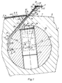
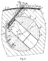
- the device according to the invention is shown in the drawing and is described in more detail below.
- a cylinder e.g. B. a blanket cylinder 1, a rotary printing machine for receiving, for example, formed as blanket units 2 plates with folded ends 3, 4 with at least one parallel to its axis of rotation, extending from a lateral surface 6 of the blanket cylinder 1 into its interior 7, narrow slot 8 Mistake.
- the rubber blanket 11 is fastened to the carrier plate 9 in such a way that both legs 12, 13 of the carrier plate 9 are free of the rubber blanket 11 at the bent ends 3, 4 of the rubber blanket unit 2 and thus only the two legs 12, 13 of the carrier plate 9 into the slot 8 protruding.
- the slot 8 is preferably rectangular in cross section.
- a bore 18 running parallel to the slot 8 is made in the rubber cylinder 1.
- the slot 8 tangent to the bore 18 in the form of a chord, so that the bore 18 is connected to the slot 8.
- there is a virtual continuation of a lateral surface 19 of the bore 18 at a distance a from a side surface 21 of the slot 8 facing away from the bore 18, the distance a being slightly greater than the thickness d9 of the carrier plate 9, for. B. a 0.4 mm.
- This spindle 22 is provided in the axial direction with a plurality of pressure pieces 23 acting radially outwards.
- the pressure pieces 23 are fastened in the spindle 22 in such a way that their pressure cams 24 can act resiliently beyond a lateral surface 26 of the spindle 22.
- the pressure cams 24 are provided at their outer end with a ball dome, but cylinder segment-shaped configurations are also possible, so that, for example, one for each pressure cam 24 line-shaped contact zone results.
- Beta 70 °
- a flexible but pressure-resistant leaf-shaped slide 32 is suspended, which in the present example is designed as a continuous steel leaf spring.
- the other, outward-facing end 30 of the slider 32 is connected to a filler 33 in a form-fitting and / or material-locking manner.
- the slider 32 can also be designed like a comb, the filler 33 can be attached to the comb back.
- This filler 33 consists, for example, of an elastic material similar to the rubber blanket 11 which is vulcanized directly onto the end 30 of the slide 32 and extends axially along the length of the slot 8 or preferably over the entire width of the rubber blanket unit 2.
- This filler 33 but can also consist of the same material as the slide 32 and be molded directly onto it. But it is also possible to form the slide 32 resilient, in which, for example, the end 30 is made of elastic material.
- the slider 32 is provided with at least one barb 36 on its side surface 34 facing the trailing end 4.
- a plurality of barbs 36 can also be arranged, which engage in corresponding recesses 37 in the leg 13 of the trailing end 4 which are adapted to the barbs 36.
- the operation of the device according to the invention is as follows: In an insertion position (FIG. 1) of the spindle 22, the slide 32 located in the slot 8 with the filler piece 33 projects beyond the lateral surface 6 of the rubber cylinder 1.
- the folded ends 3, 4 of the rubber blanket unit 2 are adapted to the angle of inclination alpha of the slot 8.
- the spindle 22 is rotated counterclockwise until the pressure pieces 23 are approximately perpendicular to the legs 12, 13 of the carrier plate 9.
- the pressure cams 24 of the pressure pieces 23 are pressed against the legs 12, 13 of the carrier plate 9 by means of spring force which is supported on the spindle 22.
- the slide 32 with the filler 33 attached to it and the leg 13 attached to the barb 36 of the trailing end 4 in the Slit 8 retracted until the filler 33 fills the remaining gap 47 of the opposite ends 44, 46 of the rubber blanket 11.
- the legs 12, 13 of the carrier plate 9 and the slide 32 are clamped in the slot 8 of the rubber cylinder 1 between the side surface 21 of the slot 8 and the pressure cam 24 (FIG. 2), with which the ends 3, 4 of the rubber blanket unit 2 are secured are attached to the rubber cylinder 1.
- the spring force and spring travel are dimensioned such that a secure clamping takes place.
Landscapes
- Supply, Installation And Extraction Of Printed Sheets Or Plates (AREA)
- Preliminary Treatment Of Fibers (AREA)
- Clamps And Clips (AREA)
- Printing Plates And Materials Therefor (AREA)
Applications Claiming Priority (2)
| Application Number | Priority Date | Filing Date | Title |
|---|---|---|---|
| DE19521645 | 1995-06-14 | ||
| DE19521645A DE19521645C2 (de) | 1995-06-14 | 1995-06-14 | Einrichtung für eine schlitzförmige Haltevorrichtung |
Publications (3)
| Publication Number | Publication Date |
|---|---|
| EP0748688A2 true EP0748688A2 (fr) | 1996-12-18 |
| EP0748688A3 EP0748688A3 (fr) | 1998-04-22 |
| EP0748688B1 EP0748688B1 (fr) | 2001-07-11 |
Family
ID=7764372
Family Applications (1)
| Application Number | Title | Priority Date | Filing Date |
|---|---|---|---|
| EP96109141A Expired - Lifetime EP0748688B1 (fr) | 1995-06-14 | 1996-06-07 | Dispositif pour un système de retenu sous forme de fente |
Country Status (4)
| Country | Link |
|---|---|
| US (1) | US5669306A (fr) |
| EP (1) | EP0748688B1 (fr) |
| JP (1) | JP3090253B2 (fr) |
| DE (2) | DE19521645C2 (fr) |
Cited By (3)
| Publication number | Priority date | Publication date | Assignee | Title |
|---|---|---|---|---|
| WO1997018954A3 (fr) * | 1995-11-23 | 1997-07-31 | Koenig & Bauer Albert Ag | Blanchet en caoutchouc pour presse |
| ITMI20081930A1 (it) * | 2008-11-03 | 2010-05-04 | Trelleborg Engineered Systems Italy S P A | Metodo di produzione di un rivestimento per un cilindro tipografico comprendente un'appendice, e rivestimento ottenuto |
| EP1712360A3 (fr) * | 2005-04-14 | 2010-05-05 | manroland AG | Dispositif de transfert d'encre d'une machine d'impression |
Families Citing this family (10)
| Publication number | Priority date | Publication date | Assignee | Title |
|---|---|---|---|---|
| DE10228970C1 (de) * | 2002-06-26 | 2003-11-13 | Koenig & Bauer Ag | Zylinder eines Druckwerks einer Rotationsdruckmaschine |
| US6714467B2 (en) * | 2002-03-19 | 2004-03-30 | Broadcom Corporation | Block redundancy implementation in heirarchical RAM's |
| DE10307382A1 (de) * | 2002-12-16 | 2004-07-08 | Koenig & Bauer Ag | Drucktucheinheit für einen Drucktuchzylinder einer Rotationsdruckmaschine und ein Verfahren zur Herstellung einer Drucktucheinheit für einen Drucktuchzylinder |
| RU2301152C2 (ru) * | 2002-12-16 | 2007-06-20 | Кениг Унд Бауер Акциенгезельшафт | Декельный узел для офсетного цилиндра и способ изготовления декельного узла |
| JP4298702B2 (ja) | 2002-12-16 | 2009-07-22 | ケーニッヒ ウント バウエル アクチエンゲゼルシャフト | 印刷機における印刷ブランケットシリンダのための印刷ブランケット装置および印刷ブランケット装置の製造方法 |
| JP4309395B2 (ja) | 2002-12-16 | 2009-08-05 | ケーニッヒ ウント バウエル アクチエンゲゼルシャフト | 印刷ブランケットシリンダのための印刷ブランケット装置および印刷ブランケット装置の製造方法 |
| DE50306334D1 (de) | 2002-12-16 | 2007-03-08 | Koenig & Bauer Ag | Drucktucheinheit und verfahren zur herstellung einer drucktucheinheit |
| US8904931B2 (en) * | 2003-11-10 | 2014-12-09 | Day International, Inc. | Printing blanket construction and method of making |
| DE10354435B4 (de) * | 2003-11-21 | 2010-02-04 | Koenig & Bauer Aktiengesellschaft | Vorrichtungen zur Herstellung einer Drucktucheinheit eines Drucktuchzylinders einer Druckmaschine |
| DE102006058667B3 (de) * | 2006-12-13 | 2008-02-07 | Koenig & Bauer Aktiengesellschaft | Druckzylinder für Rollenoffsetdruckmaschine |
Family Cites Families (13)
| Publication number | Priority date | Publication date | Assignee | Title |
|---|---|---|---|---|
| GB526837A (en) * | 1938-12-19 | 1940-09-26 | United Autographic Register Co | Improvements in or relating to printing devices |
| US2525003A (en) * | 1947-11-17 | 1950-10-10 | Commercial Lithograph Company | Method of making lithograph blankets |
| US2714852A (en) * | 1949-06-04 | 1955-08-09 | Laszlo M Stempel | Device for securing and tensioning a flexible transfer blanket on a cylinder |
| DE3110982A1 (de) * | 1981-03-20 | 1982-10-07 | M.A.N.- Roland Druckmaschinen AG, 6050 Offenbach | Plattenzylinder mit einer plattenbefestigungsvorrichtung |
| DE8433674U1 (de) * | 1984-11-16 | 1985-02-14 | Maschinenfabrik Wifag, Bern | Vorrichtung zum aufziehen eines gummituches auf einen gummituchzylinder einer rotationsdruckmaschine |
| DE3538308C2 (de) * | 1984-11-16 | 1994-02-24 | Wifag Maschf | Vorrichtung zum Aufziehen eines Gummituches auf einen Gummituchzylinder einer Rotationsdruckmaschine |
| US4635550A (en) * | 1985-03-11 | 1987-01-13 | American Roller Company | Gap filler blanket for printing cylinder |
| DE3540581A1 (de) * | 1985-11-15 | 1987-05-21 | Roland Man Druckmasch | Druckwerkzylinder mit einem in dessen zylindergrube angeordneten fuellstueck |
| DE3707066A1 (de) * | 1987-03-05 | 1988-09-15 | Roland Man Druckmasch | Spannvorrichtung zur befestigung eines aufzuges am zylinder einer rotationsdruckmaschine |
| DE4005093C1 (en) * | 1990-02-17 | 1991-06-20 | Man Roland Druckmaschinen Ag, 6050 Offenbach, De | Forme clamp for printing cylinder - has channel in cylinder with spindle to clamp form eccentrically |
| DE4102858A1 (de) * | 1990-03-08 | 1991-09-12 | Heidelberger Druckmasch Ag | Druckwerkszylinder fuer rotationsdruckmaschinen |
| US5284093A (en) * | 1993-02-24 | 1994-02-08 | Heidelberg Harris Inc. | Plate cylinder with semi-automatic plate lock up |
| DE4335140C1 (de) * | 1993-10-15 | 1995-02-02 | Roland Man Druckmasch | Vorrichtung zum Befestigen einer biegsamen Druckplatte |
-
1995
- 1995-06-14 DE DE19521645A patent/DE19521645C2/de not_active Expired - Fee Related
-
1996
- 1996-06-07 DE DE59607256T patent/DE59607256D1/de not_active Expired - Fee Related
- 1996-06-07 EP EP96109141A patent/EP0748688B1/fr not_active Expired - Lifetime
- 1996-06-10 JP JP08147356A patent/JP3090253B2/ja not_active Expired - Fee Related
- 1996-06-14 US US08/663,814 patent/US5669306A/en not_active Expired - Fee Related
Cited By (5)
| Publication number | Priority date | Publication date | Assignee | Title |
|---|---|---|---|---|
| WO1997018954A3 (fr) * | 1995-11-23 | 1997-07-31 | Koenig & Bauer Albert Ag | Blanchet en caoutchouc pour presse |
| US5934194A (en) * | 1995-11-23 | 1999-08-10 | Koenig & Bauer-Albert Aktiengesellschaft | Rubber blanket for a printing machine |
| CN1077049C (zh) * | 1995-11-23 | 2002-01-02 | 柯尼格及包尔-艾伯特公开股份有限公司 | 印刷机的橡皮布 |
| EP1712360A3 (fr) * | 2005-04-14 | 2010-05-05 | manroland AG | Dispositif de transfert d'encre d'une machine d'impression |
| ITMI20081930A1 (it) * | 2008-11-03 | 2010-05-04 | Trelleborg Engineered Systems Italy S P A | Metodo di produzione di un rivestimento per un cilindro tipografico comprendente un'appendice, e rivestimento ottenuto |
Also Published As
| Publication number | Publication date |
|---|---|
| JPH091779A (ja) | 1997-01-07 |
| DE59607256D1 (de) | 2001-08-16 |
| EP0748688A3 (fr) | 1998-04-22 |
| DE19521645C2 (de) | 1998-07-09 |
| JP3090253B2 (ja) | 2000-09-18 |
| DE19521645A1 (de) | 1997-01-09 |
| EP0748688B1 (fr) | 2001-07-11 |
| US5669306A (en) | 1997-09-23 |
Similar Documents
| Publication | Publication Date | Title |
|---|---|---|
| EP0748688B1 (fr) | Dispositif pour un système de retenu sous forme de fente | |
| EP0862519B1 (fr) | Blanchet en caoutchouc pour presse | |
| DE19924784C2 (de) | Vorrichtung zum Befestigen von biegsamen Platten auf einem Zylinder einer Rotationsdruckmaschine mit Drehrichtungsumkehr | |
| DE19509561C2 (de) | Vorrichtung zum Klemmen von Platten auf einem Zylinder | |
| EP0732202B1 (fr) | Cylindre avec un dispositif pour tendre une plaque d'impression | |
| EP0732203B1 (fr) | Dispositif tendeur | |
| DE19757895C2 (de) | Seitenregister-Einstellvorrichtung für Druckplatten | |
| EP0755785B1 (fr) | Dispositif de fixation d'une plaque avec réduction de la zône sans pression | |
| DE1997948U (de) | Loesbare nutfederverbindung zur halterung streifen- und plattenfoermiger bauteile | |
| DE3315488A1 (de) | Vorrichtung zum spannen von druckplatten | |
| DE19541249A1 (de) | Vorrichtung zum Befestigen einer Gummitucheinheit auf einem Gummizylinder | |
| DD266233A3 (de) | Vorrichtung zum befestigen einer biegsamen druckplatte | |
| EP0592856B1 (fr) | Dispositif de serrage pour fixer une forme d'impression flexible à la surface d'un cylindre | |
| DE19509562C1 (de) | Vorrichtung zum Lösen von Platten von einem Zylinder | |
| EP1268210A2 (fr) | Dispositif pour serrer et/ou bloquer des plaques souples | |
| DE19533178C2 (de) | Zylinder | |
| EP0995597B1 (fr) | Cylindre de plaque dans une machine d'impression avec dispositif de tension de plaque | |
| DE2559387A1 (de) | Sattel zur aufnahme einer flexiblen druckplatte | |
| DE7825185U1 (de) | Plattenspannvorrichtung zum aufspannen von biegsamen platten auf einem zylinder | |
| DE19524296C2 (de) | Zylinder | |
| DD149849A3 (de) | Vorrichtung zum befestigen und spannen von biegsamen druckplatten | |
| DE102022111193A1 (de) | Schleifblock | |
| DD262191A1 (de) | Vorrichtung zum befestigen einer biegsamen druckplatte | |
| DE10001323A1 (de) | Vorrichtung zum Befestigen von Aufzügen auf Druckzylindern | |
| DE8221511U1 (de) | Klemmschiene zum befestigen von druckplatten am zylinder von druckmaschinen |
Legal Events
| Date | Code | Title | Description |
|---|---|---|---|
| PUAI | Public reference made under article 153(3) epc to a published international application that has entered the european phase |
Free format text: ORIGINAL CODE: 0009012 |
|
| AK | Designated contracting states |
Kind code of ref document: A2 Designated state(s): CH DE FR GB IT LI SE |
|
| PUAL | Search report despatched |
Free format text: ORIGINAL CODE: 0009013 |
|
| AK | Designated contracting states |
Kind code of ref document: A3 Designated state(s): CH DE FR GB IT LI SE |
|
| RAP1 | Party data changed (applicant data changed or rights of an application transferred) |
Owner name: KOENIG & BAUER AKTIENGESELLSCHAFT |
|
| 17P | Request for examination filed |
Effective date: 19981016 |
|
| GRAG | Despatch of communication of intention to grant |
Free format text: ORIGINAL CODE: EPIDOS AGRA |
|
| GRAG | Despatch of communication of intention to grant |
Free format text: ORIGINAL CODE: EPIDOS AGRA |
|
| GRAH | Despatch of communication of intention to grant a patent |
Free format text: ORIGINAL CODE: EPIDOS IGRA |
|
| 17Q | First examination report despatched |
Effective date: 20001116 |
|
| GRAH | Despatch of communication of intention to grant a patent |
Free format text: ORIGINAL CODE: EPIDOS IGRA |
|
| GRAA | (expected) grant |
Free format text: ORIGINAL CODE: 0009210 |
|
| ITF | It: translation for a ep patent filed | ||
| AK | Designated contracting states |
Kind code of ref document: B1 Designated state(s): CH DE FR GB IT LI SE |
|
| REG | Reference to a national code |
Ref country code: CH Ref legal event code: EP |
|
| GBT | Gb: translation of ep patent filed (gb section 77(6)(a)/1977) |
Effective date: 20010712 |
|
| REF | Corresponds to: |
Ref document number: 59607256 Country of ref document: DE Date of ref document: 20010816 |
|
| ET | Fr: translation filed | ||
| REG | Reference to a national code |
Ref country code: GB Ref legal event code: IF02 |
|
| PLBE | No opposition filed within time limit |
Free format text: ORIGINAL CODE: 0009261 |
|
| STAA | Information on the status of an ep patent application or granted ep patent |
Free format text: STATUS: NO OPPOSITION FILED WITHIN TIME LIMIT |
|
| PGFP | Annual fee paid to national office [announced via postgrant information from national office to epo] |
Ref country code: GB Payment date: 20020527 Year of fee payment: 7 |
|
| PGFP | Annual fee paid to national office [announced via postgrant information from national office to epo] |
Ref country code: SE Payment date: 20020619 Year of fee payment: 7 Ref country code: FR Payment date: 20020619 Year of fee payment: 7 |
|
| PGFP | Annual fee paid to national office [announced via postgrant information from national office to epo] |
Ref country code: CH Payment date: 20020625 Year of fee payment: 7 |
|
| 26N | No opposition filed | ||
| PG25 | Lapsed in a contracting state [announced via postgrant information from national office to epo] |
Ref country code: GB Free format text: LAPSE BECAUSE OF NON-PAYMENT OF DUE FEES Effective date: 20030607 |
|
| PG25 | Lapsed in a contracting state [announced via postgrant information from national office to epo] |
Ref country code: SE Free format text: LAPSE BECAUSE OF NON-PAYMENT OF DUE FEES Effective date: 20030608 |
|
| PG25 | Lapsed in a contracting state [announced via postgrant information from national office to epo] |
Ref country code: LI Free format text: LAPSE BECAUSE OF NON-PAYMENT OF DUE FEES Effective date: 20030630 Ref country code: CH Free format text: LAPSE BECAUSE OF NON-PAYMENT OF DUE FEES Effective date: 20030630 |
|
| GBPC | Gb: european patent ceased through non-payment of renewal fee |
Effective date: 20030607 |
|
| EUG | Se: european patent has lapsed | ||
| REG | Reference to a national code |
Ref country code: CH Ref legal event code: PL |
|
| PG25 | Lapsed in a contracting state [announced via postgrant information from national office to epo] |
Ref country code: FR Free format text: LAPSE BECAUSE OF NON-PAYMENT OF DUE FEES Effective date: 20040227 |
|
| REG | Reference to a national code |
Ref country code: FR Ref legal event code: ST |
|
| PG25 | Lapsed in a contracting state [announced via postgrant information from national office to epo] |
Ref country code: IT Free format text: LAPSE BECAUSE OF NON-PAYMENT OF DUE FEES;WARNING: LAPSES OF ITALIAN PATENTS WITH EFFECTIVE DATE BEFORE 2007 MAY HAVE OCCURRED AT ANY TIME BEFORE 2007. THE CORRECT EFFECTIVE DATE MAY BE DIFFERENT FROM THE ONE RECORDED. Effective date: 20050607 |
|
| PGFP | Annual fee paid to national office [announced via postgrant information from national office to epo] |
Ref country code: DE Payment date: 20060626 Year of fee payment: 11 |
|
| PG25 | Lapsed in a contracting state [announced via postgrant information from national office to epo] |
Ref country code: DE Free format text: LAPSE BECAUSE OF NON-PAYMENT OF DUE FEES Effective date: 20080101 |