EP0748703B1 - Vorrichtung zur Festhalten von Papierbögen, Dateien oder Lochkarten in Ordnern oder dergleichen - Google Patents
Vorrichtung zur Festhalten von Papierbögen, Dateien oder Lochkarten in Ordnern oder dergleichen Download PDFInfo
- Publication number
- EP0748703B1 EP0748703B1 EP96108843A EP96108843A EP0748703B1 EP 0748703 B1 EP0748703 B1 EP 0748703B1 EP 96108843 A EP96108843 A EP 96108843A EP 96108843 A EP96108843 A EP 96108843A EP 0748703 B1 EP0748703 B1 EP 0748703B1
- Authority
- EP
- European Patent Office
- Prior art keywords
- base portion
- arms
- cover
- button
- binder
- Prior art date
- Legal status (The legal status is an assumption and is not a legal conclusion. Google has not performed a legal analysis and makes no representation as to the accuracy of the status listed.)
- Expired - Lifetime
Links
- 239000011230 binding agent Substances 0.000 title claims abstract description 32
- 229920002994 synthetic fiber Polymers 0.000 claims description 4
- 230000000284 resting effect Effects 0.000 claims description 2
- 229910000831 Steel Inorganic materials 0.000 description 4
- 239000000463 material Substances 0.000 description 4
- 239000010959 steel Substances 0.000 description 4
- 230000006378 damage Effects 0.000 description 3
- 208000014674 injury Diseases 0.000 description 3
- 208000012260 Accidental injury Diseases 0.000 description 2
- 238000004519 manufacturing process Methods 0.000 description 2
- 230000007246 mechanism Effects 0.000 description 2
- 208000027418 Wounds and injury Diseases 0.000 description 1
- 238000006243 chemical reaction Methods 0.000 description 1
- 239000003086 colorant Substances 0.000 description 1
- 238000003780 insertion Methods 0.000 description 1
- 230000037431 insertion Effects 0.000 description 1
- 230000000670 limiting effect Effects 0.000 description 1
- 230000014759 maintenance of location Effects 0.000 description 1
- 238000006798 ring closing metathesis reaction Methods 0.000 description 1
Images


Classifications
-
- B—PERFORMING OPERATIONS; TRANSPORTING
- B42—BOOKBINDING; ALBUMS; FILES; SPECIAL PRINTED MATTER
- B42F—SHEETS TEMPORARILY ATTACHED TOGETHER; FILING APPLIANCES; FILE CARDS; INDEXING
- B42F13/00—Filing appliances with means for engaging perforations or slots
- B42F13/0006—Covers for loose-leaf binders
- B42F13/0066—Covers for loose-leaf binders with means for attaching the filing appliance to the cover
- B42F13/0073—Covers for loose-leaf binders with means for attaching the filing appliance to the cover removable
Definitions
- the present invention relates to a device for retaining sheets, files, or punched cards in binders or the like.
- the devices currently in use for retaining sheets, files, or punched cards inside binders are generally constituted by steel mechanisms, having various shapes and dimensions, that are provided with a plurality of rings, each of which is composed of two halves that can be separated to insert the various pre-perforated sheets, in contrast with the action applied by appropriate springs that achieve, for each ring, an opening position and a closure position.
- these steel mechanisms can very easily cause injuries to the user's hands during the operation for ring closure, which occurs suddenly due to the action applied by the springs.
- Another problem consists in the difficulty in disposing of old binders provided with these steel devices in an environment-friendly manner, since in order to permit separate-collection of the different materials constituting such binders, it is necessary to first detach the steel devices from the cover, which is usually made of cardboard.
- Another problem is constituted by the fact that a partial breakage or damage of the device usually necessitates replacement of the entire binder.
- WO-A-91/11 333 discloses a device for retaining sheets, files or punched cards in binders, as recited in the preamble of claim 1.
- the aim of the present invention is to solve the above described problems by providing a device for retaining sheets, files, or punched cards in binders or the like that is very practical and handy in use and offers a high degree safety against the danger of accidental injury.
- an object of the present invention is to provide a device that is structurally simple and can be manufactured with considerably lower production costs than those of currently commercially available binder devices.
- Another object of the present invention is to provide a device that considerably simplifies the operations for the disposal of the binders once they have reached the end of their working life.
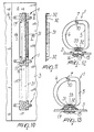
- the device comprises a body 1 preferably made of molded synthetic material that has a base portion 2, which is associable with the cover 3 of a binder 4 or the like, and two arms 5 and 6 that extend from the base portion 2 and constitute the two arms of an open ring.
- the two arms 5 and 6 can be moved mutually closer with their free ends 5a and 6a, i.e., their ends that are opposite with respect to the base portion 2; said free ends 5a and 6a are provided with mutual engagement means that can be activated or deactivated to close or open the ring constituted by the two arms 5 and 6.
- the two arms 5 and 6 and the base portion 2 are preferably formed monolithically.
- the two arms 5 and 6 can be moved mutually closer or further apart with their free ends 5a and 6a as a consequence of the elastic flexural deformability of said arms 5 and 6 and/or of the base portion 2.
- the body made of synthetic material constituted by the base portion 2 and by the two arms 5 and 6, is molded monolithically with the two arms 5 and 6, which are mutually disengaged and spaced apart.
- the mutual engagement means supported by the free ends 5a and 6a comprise, on the arm 5, a tooth 7 and a seat 8 that can engage in a snap-together fashion, by mutual overlap, respectively a seat 9 and a tooth 10 that are formed on the free end 6a of the other arm 6.
- the two arms 5 and 6 have, in transverse cross-section, a circular shape except for their free end 5a and 6a and for the region for connection to the base portion 2.
- the two arms 5 and 6 are connected to the base portion 2 by means of a flap that is composed of a first portion 11a and 12a, which rises vertically from the base portion 2, and of a second portion 11b, 12b, which extends at right angles to the first portion 11a, 12a, i.e., horizontally.
- This particular connection existing between the arms 5 and 6 and the base portion 2 ensures high elastic flexural deformability of the two arms 5 and 6 toward and away from each other.
- the device according to the invention is also provided with means for removable engagement of the base portion 2 with the cover 3 of the binder 4.
- the base portion 2 is provided with a foot 13 that has a prism-like shape and can be inserted, from the inner side of the cover 3, in a through seat 14 that is formed correspondingly in the cover 3 of the binder 4.
- the removable engagement means comprise a button 15 that is associable with the foot 13 of the base portion 2 on the outer side of the cover 3 to clamp the cover between the base portion 2 and the button 15.
- the button 15 is provided, on one of its faces, with a pivot 16 that has, proximate to its opposite end with respect to the button 15, a pair of transverse tabs 17 that protrude in mutually diametrically opposite regions.
- Said pivot 16 can be inserted through an elongated slot 18 that is formed in the base portion 2 and can rotate about its axis relative to the base portion 2 to move the tabs 17 transversely to the elongated slot 18, thus producing the stable connection of the button 15 to the base portion 2.
- the base portion 2 on its side directed away from the button 15, is provided, around the elongated slot 18, with a path formed by inclined planes 19a and 19b that end with recesses 20a and 20b for accommodating the transverse tabs 17.
- the button 15 has, on its opposite side with respect to the pivot 16, a maneuvering slot 21 by means of which it is possible to turn the button 15 about the axis of the pivot 16 in a very simple manner with a coin 30, with a screwdriver, or with another blade-fitted tool.
- the base portion 2 is also provided, laterally to the foot 13, with flaps 22 for resting against the inner side of the cover 3.
- bars 31 may be provided for interconnecting two contiguous bodies 1 of the devices of the above-described type, after they have been connected to the cover 3 by means of respective buttons 15.
- the bars 31, which may also be made of molded synthetic material, have protuberances 32 located on a portion thereof which is adapted to face the cover.
- the protuberances 32 have a wing-like shape and define a cavity 33 which can be press-fitted onto one of the tabs 17 of a pivot 16 of a respective button 15.
- connection rib is provided between a plurality of devices according to the invention, in an aesthetically pleasing manner.
- binders with a variable number of devices according to the invention are produced.
- the devices according to the invention can be supplied unassembled to the cover of the binder, leaving this operation to the end user, so as to considerably reduce costs linked to transport and storage, thus reducing the total cost of the binder.
- the device is assembled to the cover 4 by using the button 15, which is inserted with the transverse tabs 17 of the pivot 16 through the elongated slot 18 of the base portion 2 and then fixed stably to said base portion 2, partially turning it about the axis of the pivot 16.
- the engagement of the transverse tabs 17 along the inclined paths 19a and 19b causes the gradual clamping of the cover 3 between the flaps 22 of the base portion 2 and the button 15 as well as the subsequent stable retention of the transverse tabs 17 in the recesses 20a and 20b.
- the bodies 1 of the devices can be interconnected by means of the bars 31.
- the two arms 5 and 6 can be moved mutually closer in contrast with the elastic reaction of the material, mutually overlapping the free ends 5a and 6a, with consequent snap-action engagement of the teeth 7 and 10 in the seats 8 and 9.
- the ring constituted by the arms 5 and 6 is stably closed and retains the sheets inside the binder.
- the device according to the invention fully achieves the intended aim, since by being provided with mutual engagement means at the free ends of the two arms that compose each ring, it is extremely practical and easy to use and safely avoids the possibility of accidental injury to the user.
- Another advantage of the device according to the invention is that it can be produced in various colors, according to the image and design requirements that the market demands in each case.
- An additional advantage is that it allows the user, if damage occurs to a ring inside a binder, to replace just the damaged ring without having to replace the entire binder.
- the materials employed, as well as the dimensions, may be any according to the requirements and the state of the art.
Landscapes
- Sheet Holders (AREA)
- Discharge By Other Means (AREA)
- Credit Cards Or The Like (AREA)
- Packaging For Recording Disks (AREA)
Claims (17)
- Vorrichtung zum Festhalten von Blättern, Akten oder Lochkarten in Mappen oder dergleichen, welche folgendes umfaßt:dadurch gekennzeichnet, daß die Vorrichtung für den lösbaren Eingriff des Basisteils den Basisteil durch den Deckel hindurch verbindet und von der Außenseite des Deckels zugänglich ist, um den Basisteil zu verriegeln/entriegeln.einen Körper (1) mit einem Basisteil (2), der mit dem Deckel (3) einer Mappe (4) oder dergleichen verbindbar ist;zwei Schenkel (5, 6), die sich von dem Basisteil (2) erstrecken und die zwei Schenkel eines offenen Rings bilden, wobei die zwei Schenkel (5, 6) mittels ihrer freien Enden (5a, 6a), die zum Basisteil entgegengesetzt liegen, zueinander hin bewegbar sind;Vorrichtungen (7, 8) für einen gegenseitigen Eingriff, die an den freien Enden (7, 8) vorgesehen sind, wobei die Eingriffsvorrichtungen aktiviert oder deaktiviert werden, um den Ring zu schließen oder zu öffnen; undeine Vorrichtung für den lösbaren Eingriff des Basisteils mit dem Deckel der Mappe oder dergleichen;
- Vorrichtung nach Anspruch 1, dadurch gekennzeichnet, daß der Basisteil einen Fuß aufweist, der eine prismatische Form aufweist und von der Innenseite des Deckels in einen Durchgangssitz eingesetzt werden kann, der entsprechend im Deckel der Mappe oder dergleichen ausgebildet ist, wobei die lösbare Eingriffsvorrichtung einen Knopf umfaßt, der mit dem Fuß des Basisteils an der Außenseite des Deckels verbindbar ist, um den Deckel zwischen dem Basisteil und dem Knopf einzuklemmen.
- Vorrichtung nach Anspruch 2, dadurch gekennzeichnet, daß der Knopf einen Kopf mit einem Drehzapfen aufweist, der mit einem Paar von diametral entgegengesetzten Quervorsprüngen versehen ist, wobei der Drehzapfen durch einen langgestreckten Schlitz, der in dem Basisteil ausgebildet ist, einsetzbar ist und sich relativ zum Basisteil um seine eigene Achse drehen kann, um die Vorsprünge quer zu dem langgestreckten Schlitz zu bewegen, was die stabile Verbindung des Knopfs mit dem Basisteil durchführt.
- Vorrichtung nach einem oder mehreren der vorangehenden Ansprüche, dadurch gekennzeichnet, daß der Basisteil auf seiner Seite, die von dem Knopf weggerichtet ist, um den langgestreckten Schlitz einen Weg aufweist, der durch schräge Ebenen für die Quervorsprünge des Drehzapfens des Knopfs ausgebildet ist, wobei die Ebenen mit Aussparungen zum Aufnehmen der Quervorsprünge enden.
- Vorrichtung nach einem oder mehreren der vorangehenden Ansprüche, dadurch gekennzeichnet, daß der Basisteil seitlich zum Fuß Flügel zum Anlegen an die Innenseite des Deckels aufweist.
- Vorrichtung nach einem oder mehreren der vorangehenden Ansprüche, dadurch gekennzeichnet, daß der Knopf einen Bedienungsschlitz auf seiner Seite, die vom Drehzapfen weggerichtet ist, aufweist.
- Vorrichtung nach einem oder mehreren der vorangehenden Ansprüche, dadurch gekennzeichnet, daß sie mindestens eine Stange umfaßt, die zum Verbinden von mindestens zwei benachbarten Körpern, die zu dem Körper im wesentlichen identisch sind, mit dem Körper verbindbar ist, wobei die Stange mit dem Deckel einer Mappe verbindbar ist.
- Vorrichtung nach einem oder mehreren der vorangehenden Ansprüche, dadurch gekennzeichnet, daß die Stange auf einer Seite derselben, die so ausgelegt ist, daß sie einem Deckel einer Mappe zugewandt ist, Ausstülpungen aufweist, die für einen Preßsitzeingriff mit den Vorsprüngen des Drehzapfens ausgelegt sind, welcher durch die Knöpfe festgelegt wird, die mit dem Basisteil von jedem der mindestens zwei benachbarten Körper in Eingriff stehen.
- Vorrichtung nach Anspruch 1, dadurch gekennzeichnet, daß der Körper aus geformtem synthetischen Material besteht.
- Vorrichtung nach Anspruch 1, dadurch gekennzeichnet, daß die zwei Schenkel und der Basisteil monolithisch ausgebildet sind.
- Vorrichtung nach Anspruch 1, dadurch gekennzeichnet, daß die Schenkel infolge der elastischen Biegeverformbarkeit der zwei Schenkel und/oder des Basisteils mit ihren freien Enden näher zueinander oder weiter auseinander bewegt werden können.
- Vorrichtung nach Anspruch 1, dadurch gekennzeichnet, daß, wenn die Vorrichtungen für den gegenseitigen Eingriff deaktiviert werden und wenn keine Kräfte auf die zwei Schenkel aufgebracht werden, die freien Enden der zwei Schenkel voneinander beabstandet sind.
- Vorrichtung nach Anspruch 1, dadurch gekennzeichnet, daß die Vorrichtungen für den gegenseitigen Eingriff mindestens einen Zahn umfassen, der am freien Ende von einem der zwei Schenkel vorgesehen ist und in einer zusammenschnappenden Weise mit einem Sitz in Eingriff kommen kann, der entsprechend im freien Ende des anderen der zwei Schenkel ausgebildet ist.
- Vorrichtung nach Anspruch 1, dadurch gekennzeichnet, daß die Vorrichtungen für den gegenseitigen Eingriff für jeden der zwei Schenkel einen Zahn und einen Sitz umfassen, die in einer zusammenschnappenden Weise durch gegenseitige Überlappung jeweils mit einem Sitz und einem Zahn in Eingriff kommen können, die am anderen der zwei Schenkel ausgebildet sind.
- Vorrichtung nach Anspruch 1, dadurch gekennzeichnet, daß die zwei Schenkel in einem Querschnitt eine Kreisform aufweisen, abgesehen von ihrem freien Ende und vom Bereich zum Verbinden mit dem Basisteil.
- Vorrichtung nach Anspruch 1, dadurch gekennzeichnet, daß die zwei Schenkel mit dem Basisteil mittels eines Flügels verbunden sind, der einen ersten Teil, der sich vertikal vom Basisteil erstreckt, und einen zweiten Teil, der mit einem der zwei Schenkel verbunden ist und horizontal liegt, aufweist.
- Mappe zum Festhalten von Blättern, Akten oder Lochkarten, dadurch gekennzeichnet, daß sie einen Deckel umfaßt, auf den mindestens eine Vorrichtung nach einem oder mehreren der vorangehenden Ansprüche lösbar aufgebracht ist.
Applications Claiming Priority (2)
| Application Number | Priority Date | Filing Date | Title |
|---|---|---|---|
| ITMI951275 | 1995-06-14 | ||
| IT95MI001275A IT1276720B1 (it) | 1995-06-14 | 1995-06-14 | Dispositivo per il trattenimento di fogli, fascicoli, o schede perforate, in raccoglitori, o simili |
Publications (3)
| Publication Number | Publication Date |
|---|---|
| EP0748703A2 EP0748703A2 (de) | 1996-12-18 |
| EP0748703A3 EP0748703A3 (de) | 1997-12-17 |
| EP0748703B1 true EP0748703B1 (de) | 2002-03-06 |
Family
ID=11371813
Family Applications (1)
| Application Number | Title | Priority Date | Filing Date |
|---|---|---|---|
| EP96108843A Expired - Lifetime EP0748703B1 (de) | 1995-06-14 | 1996-06-03 | Vorrichtung zur Festhalten von Papierbögen, Dateien oder Lochkarten in Ordnern oder dergleichen |
Country Status (6)
| Country | Link |
|---|---|
| US (1) | US5683193A (de) |
| EP (1) | EP0748703B1 (de) |
| AT (1) | ATE214005T1 (de) |
| DE (1) | DE69619594T2 (de) |
| ES (1) | ES2173998T3 (de) |
| IT (1) | IT1276720B1 (de) |
Cited By (1)
| Publication number | Priority date | Publication date | Assignee | Title |
|---|---|---|---|---|
| WO2015023758A1 (en) * | 2013-08-13 | 2015-02-19 | ACCO Brands Corporation | Device with quick-attach feature |
Families Citing this family (9)
| Publication number | Priority date | Publication date | Assignee | Title |
|---|---|---|---|---|
| GB9817162D0 (en) * | 1998-08-06 | 1998-10-07 | Folders Galore Ltd | Leaf retaining means |
| UA72525C2 (uk) | 1999-06-05 | 2005-03-15 | Юнівенчер, Інк. | Пристрій для зберігання (варіанти) |
| DE20019052U1 (de) * | 2000-11-09 | 2001-01-18 | Bodensee Organisation Products GmbH & Co., 88074 Meckenbeuren | Ringbuch mit neuartiger Befestigung für die Ringmechanik |
| JP2004243756A (ja) * | 2003-01-22 | 2004-09-02 | Kokuyo Co Ltd | ファイル及び綴じ具 |
| US20060024124A1 (en) * | 2004-07-27 | 2006-02-02 | World Wide Stationery Mfg. Co., Ltd. | Ring binder mechanism |
| US9290035B2 (en) | 2005-02-18 | 2016-03-22 | ACCO Brands Corporation | Refillable notebook with release mechanism |
| MX2007010078A (es) | 2005-02-18 | 2007-10-16 | Meadwestvaco Corp | Cuaderno recargable. |
| US7445396B2 (en) * | 2007-01-15 | 2008-11-04 | World Wide Stationery Mfg. Co., Ltd. | Hangable ring mechanism |
| CN101224682A (zh) * | 2007-01-16 | 2008-07-23 | 国际文具制造厂有限公司 | 杠杆夹机构 |
Family Cites Families (5)
| Publication number | Priority date | Publication date | Assignee | Title |
|---|---|---|---|---|
| GB219478A (en) * | 1923-07-10 | 1924-07-31 | Herm Herdegen | Device for detachably mounting letter-file mechanisms |
| IL81263A (en) * | 1987-01-14 | 1991-05-12 | Shakbar Investments Ltd | Fastener structure for files and multi-purpose clip for use therewith |
| GB9002533D0 (en) * | 1990-02-05 | 1990-04-04 | I P Innovations Ltd | An improved filing system |
| AU655637B2 (en) * | 1991-03-21 | 1995-01-05 | Albox Australia Pty Ltd | Paper binder for folders |
| US5154528A (en) * | 1991-09-30 | 1992-10-13 | Cananzey Gary M | U-bind page holder |
-
1995
- 1995-06-14 IT IT95MI001275A patent/IT1276720B1/it active IP Right Grant
-
1996
- 1996-06-03 US US08/657,213 patent/US5683193A/en not_active Expired - Lifetime
- 1996-06-03 DE DE69619594T patent/DE69619594T2/de not_active Expired - Lifetime
- 1996-06-03 AT AT96108843T patent/ATE214005T1/de not_active IP Right Cessation
- 1996-06-03 ES ES96108843T patent/ES2173998T3/es not_active Expired - Lifetime
- 1996-06-03 EP EP96108843A patent/EP0748703B1/de not_active Expired - Lifetime
Cited By (2)
| Publication number | Priority date | Publication date | Assignee | Title |
|---|---|---|---|---|
| WO2015023758A1 (en) * | 2013-08-13 | 2015-02-19 | ACCO Brands Corporation | Device with quick-attach feature |
| US10086637B2 (en) | 2013-08-13 | 2018-10-02 | ACCO Brands Corporation | Device with quick-attach feature |
Also Published As
| Publication number | Publication date |
|---|---|
| ITMI951275A0 (it) | 1995-06-14 |
| US5683193A (en) | 1997-11-04 |
| EP0748703A3 (de) | 1997-12-17 |
| IT1276720B1 (it) | 1997-11-03 |
| EP0748703A2 (de) | 1996-12-18 |
| ITMI951275A1 (it) | 1996-12-14 |
| ATE214005T1 (de) | 2002-03-15 |
| ES2173998T3 (es) | 2002-11-01 |
| DE69619594T2 (de) | 2002-10-24 |
| DE69619594D1 (de) | 2002-04-11 |
Similar Documents
| Publication | Publication Date | Title |
|---|---|---|
| EP0748703B1 (de) | Vorrichtung zur Festhalten von Papierbögen, Dateien oder Lochkarten in Ordnern oder dergleichen | |
| EP0682484B1 (de) | Öffenbarer ring mit zwischenelement | |
| CA2179529C (en) | Ring binder | |
| US6276862B1 (en) | Binder mechanism | |
| CA2063786C (en) | Lockable ring binder mechanism | |
| US5735296A (en) | Hair holder | |
| US4220017A (en) | Convertible finger ring | |
| EP1171313A1 (de) | Ringordner mit verriegelung | |
| US5810500A (en) | Ring binder | |
| US4792253A (en) | Binder ring having slip-on folio stops | |
| CA2053605A1 (en) | Shell buckle | |
| WO2022182990A1 (en) | Systems and methods for an improved rotary closure | |
| US20020015613A1 (en) | Fastener for a folder | |
| US6233793B1 (en) | Two-step garment closure, epecially as a front closure for a brassiers | |
| US4915215A (en) | Card carrier device and attachment mechanism | |
| EP0389594A4 (en) | Key ring | |
| KR100478643B1 (ko) | 슬라이드 파스너 | |
| EP0370368A2 (de) | Tasche, Koffer und ähnliches zum Befestigen an Motorrädern | |
| US20040168937A1 (en) | Case for holding a disc-shaped article | |
| EP1231112A2 (de) | Kraftfahrzeugdachkoffer mit verbesserter Verschlussvorrichtung | |
| US3765201A (en) | Key holder | |
| US4747165A (en) | Belt and buckle | |
| US5299372A (en) | Press for smoothing creases on ties | |
| USD474714S1 (en) | Safety belt buckle for children | |
| USD316996S (en) | Auto rear view safety mirror |
Legal Events
| Date | Code | Title | Description |
|---|---|---|---|
| PUAI | Public reference made under article 153(3) epc to a published international application that has entered the european phase |
Free format text: ORIGINAL CODE: 0009012 |
|
| AK | Designated contracting states |
Kind code of ref document: A2 Designated state(s): AT BE CH DE DK ES FR GB GR IE IT LI LU NL PT SE |
|
| PUAL | Search report despatched |
Free format text: ORIGINAL CODE: 0009013 |
|
| AK | Designated contracting states |
Kind code of ref document: A3 Designated state(s): AT BE CH DE DK ES FR GB GR IE IT LI LU NL PT SE |
|
| 17P | Request for examination filed |
Effective date: 19980525 |
|
| 17Q | First examination report despatched |
Effective date: 19990420 |
|
| GRAG | Despatch of communication of intention to grant |
Free format text: ORIGINAL CODE: EPIDOS AGRA |
|
| GRAG | Despatch of communication of intention to grant |
Free format text: ORIGINAL CODE: EPIDOS AGRA |
|
| GRAH | Despatch of communication of intention to grant a patent |
Free format text: ORIGINAL CODE: EPIDOS IGRA |
|
| GRAH | Despatch of communication of intention to grant a patent |
Free format text: ORIGINAL CODE: EPIDOS IGRA |
|
| REG | Reference to a national code |
Ref country code: GB Ref legal event code: IF02 |
|
| GRAA | (expected) grant |
Free format text: ORIGINAL CODE: 0009210 |
|
| AK | Designated contracting states |
Kind code of ref document: B1 Designated state(s): AT BE CH DE DK ES FR GB GR IE IT LI LU NL PT SE |
|
| PG25 | Lapsed in a contracting state [announced via postgrant information from national office to epo] |
Ref country code: NL Free format text: LAPSE BECAUSE OF FAILURE TO SUBMIT A TRANSLATION OF THE DESCRIPTION OR TO PAY THE FEE WITHIN THE PRESCRIBED TIME-LIMIT Effective date: 20020306 Ref country code: LI Free format text: LAPSE BECAUSE OF FAILURE TO SUBMIT A TRANSLATION OF THE DESCRIPTION OR TO PAY THE FEE WITHIN THE PRESCRIBED TIME-LIMIT Effective date: 20020306 Ref country code: GR Free format text: LAPSE BECAUSE OF FAILURE TO SUBMIT A TRANSLATION OF THE DESCRIPTION OR TO PAY THE FEE WITHIN THE PRESCRIBED TIME-LIMIT Effective date: 20020306 Ref country code: CH Free format text: LAPSE BECAUSE OF FAILURE TO SUBMIT A TRANSLATION OF THE DESCRIPTION OR TO PAY THE FEE WITHIN THE PRESCRIBED TIME-LIMIT Effective date: 20020306 Ref country code: BE Free format text: LAPSE BECAUSE OF FAILURE TO SUBMIT A TRANSLATION OF THE DESCRIPTION OR TO PAY THE FEE WITHIN THE PRESCRIBED TIME-LIMIT Effective date: 20020306 Ref country code: AT Free format text: LAPSE BECAUSE OF FAILURE TO SUBMIT A TRANSLATION OF THE DESCRIPTION OR TO PAY THE FEE WITHIN THE PRESCRIBED TIME-LIMIT Effective date: 20020306 |
|
| REF | Corresponds to: |
Ref document number: 214005 Country of ref document: AT Date of ref document: 20020315 Kind code of ref document: T |
|
| REG | Reference to a national code |
Ref country code: CH Ref legal event code: EP |
|
| REF | Corresponds to: |
Ref document number: 69619594 Country of ref document: DE Date of ref document: 20020411 |
|
| RAP2 | Party data changed (patent owner data changed or rights of a patent transferred) |
Owner name: TECNOCART S.A.S. DI GIOVANNI LEOPOLDO CERRI & C. |
|
| PG25 | Lapsed in a contracting state [announced via postgrant information from national office to epo] |
Ref country code: LU Free format text: LAPSE BECAUSE OF NON-PAYMENT OF DUE FEES Effective date: 20020603 Ref country code: IE Free format text: LAPSE BECAUSE OF NON-PAYMENT OF DUE FEES Effective date: 20020603 |
|
| PG25 | Lapsed in a contracting state [announced via postgrant information from national office to epo] |
Ref country code: SE Free format text: LAPSE BECAUSE OF FAILURE TO SUBMIT A TRANSLATION OF THE DESCRIPTION OR TO PAY THE FEE WITHIN THE PRESCRIBED TIME-LIMIT Effective date: 20020606 Ref country code: PT Free format text: LAPSE BECAUSE OF FAILURE TO SUBMIT A TRANSLATION OF THE DESCRIPTION OR TO PAY THE FEE WITHIN THE PRESCRIBED TIME-LIMIT Effective date: 20020606 Ref country code: DK Free format text: LAPSE BECAUSE OF FAILURE TO SUBMIT A TRANSLATION OF THE DESCRIPTION OR TO PAY THE FEE WITHIN THE PRESCRIBED TIME-LIMIT Effective date: 20020606 |
|
| NLT2 | Nl: modifications (of names), taken from the european patent patent bulletin |
Owner name: TECNOCART S.A.S. DI GIOVANNI LEOPOLDO CERRI & C. |
|
| NLV1 | Nl: lapsed or annulled due to failure to fulfill the requirements of art. 29p and 29m of the patents act | ||
| ET | Fr: translation filed | ||
| REG | Reference to a national code |
Ref country code: CH Ref legal event code: PL |
|
| REG | Reference to a national code |
Ref country code: ES Ref legal event code: FG2A Ref document number: 2173998 Country of ref document: ES Kind code of ref document: T3 |
|
| PLBE | No opposition filed within time limit |
Free format text: ORIGINAL CODE: 0009261 |
|
| STAA | Information on the status of an ep patent application or granted ep patent |
Free format text: STATUS: NO OPPOSITION FILED WITHIN TIME LIMIT |
|
| 26N | No opposition filed |
Effective date: 20021209 |
|
| REG | Reference to a national code |
Ref country code: IE Ref legal event code: MM4A |
|
| PGFP | Annual fee paid to national office [announced via postgrant information from national office to epo] |
Ref country code: GB Payment date: 20120620 Year of fee payment: 17 |
|
| PGFP | Annual fee paid to national office [announced via postgrant information from national office to epo] |
Ref country code: IT Payment date: 20120613 Year of fee payment: 17 |
|
| PGFP | Annual fee paid to national office [announced via postgrant information from national office to epo] |
Ref country code: DE Payment date: 20120814 Year of fee payment: 17 Ref country code: FR Payment date: 20120711 Year of fee payment: 17 Ref country code: ES Payment date: 20120629 Year of fee payment: 17 |
|
| GBPC | Gb: european patent ceased through non-payment of renewal fee |
Effective date: 20130603 |
|
| REG | Reference to a national code |
Ref country code: DE Ref legal event code: R119 Ref document number: 69619594 Country of ref document: DE Effective date: 20140101 |
|
| REG | Reference to a national code |
Ref country code: FR Ref legal event code: ST Effective date: 20140228 |
|
| PG25 | Lapsed in a contracting state [announced via postgrant information from national office to epo] |
Ref country code: GB Free format text: LAPSE BECAUSE OF NON-PAYMENT OF DUE FEES Effective date: 20130603 Ref country code: DE Free format text: LAPSE BECAUSE OF NON-PAYMENT OF DUE FEES Effective date: 20140101 |
|
| PG25 | Lapsed in a contracting state [announced via postgrant information from national office to epo] |
Ref country code: FR Free format text: LAPSE BECAUSE OF NON-PAYMENT OF DUE FEES Effective date: 20130701 Ref country code: IT Free format text: LAPSE BECAUSE OF NON-PAYMENT OF DUE FEES Effective date: 20130603 |
|
| REG | Reference to a national code |
Ref country code: ES Ref legal event code: FD2A Effective date: 20140707 |
|
| PG25 | Lapsed in a contracting state [announced via postgrant information from national office to epo] |
Ref country code: ES Free format text: LAPSE BECAUSE OF NON-PAYMENT OF DUE FEES Effective date: 20130604 |