EP0748706A2 - Bandage pneumatique pour véhicule automobile, doté d'un support de sécurité - Google Patents
Bandage pneumatique pour véhicule automobile, doté d'un support de sécurité Download PDFInfo
- Publication number
- EP0748706A2 EP0748706A2 EP96106940A EP96106940A EP0748706A2 EP 0748706 A2 EP0748706 A2 EP 0748706A2 EP 96106940 A EP96106940 A EP 96106940A EP 96106940 A EP96106940 A EP 96106940A EP 0748706 A2 EP0748706 A2 EP 0748706A2
- Authority
- EP
- European Patent Office
- Prior art keywords
- tire
- rim
- vehicle wheel
- emergency running
- wheel according
- Prior art date
- Legal status (The legal status is an assumption and is not a legal conclusion. Google has not performed a legal analysis and makes no representation as to the accuracy of the status listed.)
- Withdrawn
Links
- 239000006260 foam Substances 0.000 claims abstract description 29
- 229920001971 elastomer Polymers 0.000 claims description 14
- 239000011324 bead Substances 0.000 claims description 13
- 239000000314 lubricant Substances 0.000 claims description 10
- 238000004519 manufacturing process Methods 0.000 claims description 10
- 239000000806 elastomer Substances 0.000 claims description 4
- 239000000463 material Substances 0.000 claims description 2
- 238000000034 method Methods 0.000 abstract description 6
- 230000002787 reinforcement Effects 0.000 description 3
- 238000004073 vulcanization Methods 0.000 description 2
- 230000006378 damage Effects 0.000 description 1
- 239000004744 fabric Substances 0.000 description 1
Images

Classifications
-
- B—PERFORMING OPERATIONS; TRANSPORTING
- B60—VEHICLES IN GENERAL
- B60C—VEHICLE TYRES; TYRE INFLATION; TYRE CHANGING; CONNECTING VALVES TO INFLATABLE ELASTIC BODIES IN GENERAL; DEVICES OR ARRANGEMENTS RELATED TO TYRES
- B60C17/00—Tyres characterised by means enabling restricted operation in damaged or deflated condition; Accessories therefor
- B60C17/04—Tyres characterised by means enabling restricted operation in damaged or deflated condition; Accessories therefor utilising additional non-inflatable supports which become load-supporting in emergency
- B60C17/06—Tyres characterised by means enabling restricted operation in damaged or deflated condition; Accessories therefor utilising additional non-inflatable supports which become load-supporting in emergency resilient
-
- B—PERFORMING OPERATIONS; TRANSPORTING
- B29—WORKING OF PLASTICS; WORKING OF SUBSTANCES IN A PLASTIC STATE IN GENERAL
- B29D—PRODUCING PARTICULAR ARTICLES FROM PLASTICS OR FROM SUBSTANCES IN A PLASTIC STATE
- B29D30/00—Producing pneumatic or solid tyres or parts thereof
- B29D30/04—Resilient fillings for rubber tyres; Filling tyres therewith
-
- B—PERFORMING OPERATIONS; TRANSPORTING
- B60—VEHICLES IN GENERAL
- B60C—VEHICLE TYRES; TYRE INFLATION; TYRE CHANGING; CONNECTING VALVES TO INFLATABLE ELASTIC BODIES IN GENERAL; DEVICES OR ARRANGEMENTS RELATED TO TYRES
- B60C17/00—Tyres characterised by means enabling restricted operation in damaged or deflated condition; Accessories therefor
- B60C17/04—Tyres characterised by means enabling restricted operation in damaged or deflated condition; Accessories therefor utilising additional non-inflatable supports which become load-supporting in emergency
- B60C17/06—Tyres characterised by means enabling restricted operation in damaged or deflated condition; Accessories therefor utilising additional non-inflatable supports which become load-supporting in emergency resilient
- B60C17/065—Tyres characterised by means enabling restricted operation in damaged or deflated condition; Accessories therefor utilising additional non-inflatable supports which become load-supporting in emergency resilient made-up of foam inserts
-
- B—PERFORMING OPERATIONS; TRANSPORTING
- B60—VEHICLES IN GENERAL
- B60C—VEHICLE TYRES; TYRE INFLATION; TYRE CHANGING; CONNECTING VALVES TO INFLATABLE ELASTIC BODIES IN GENERAL; DEVICES OR ARRANGEMENTS RELATED TO TYRES
- B60C17/00—Tyres characterised by means enabling restricted operation in damaged or deflated condition; Accessories therefor
- B60C17/10—Internal lubrication
Definitions
- the invention relates first of all to a method for producing an emergency running vehicle wheel, consisting of a rim flange and a rim bed and an air-filled vehicle tire consisting essentially of rubber or a similar elastomer, in which an inner tire filled with foam is inserted as an emergency running support body.
- a motor vehicle normally stops with flat tires and can only be driven to a very limited extent because the rim flanges have severed the treads within a very short time and the wheel has no traction anymore.
- an emergency tire made of a foam which can be pushed laterally over a split, rim-free rim into its emergency running position and allows a vehicle to continue driving even with destroyed tires.
- a run-flat tire must be manufactured separately and requires a special rim that is suitable and specially manufactured for it.
- the object of the present invention is to provide a method of the type described at the outset with which complex devices and costly assembly work can be avoided and after which a vehicle wheel can be equipped to be capable of emergency operation with little effort.
- This object is achieved in that a one-piece rim is used, a tubular inner tire made of rubber is inserted into the rim well in a depressurized state, the tire is pulled over the depressurized tubular inner tire onto the rim and the foam filling after the tire has been installed in the tubular inner tire is filled.
- tubular inner tire is vulcanized to the inner wall of the tire in the region of the tire beads.
- emergency running support body is semi-tubular and the Foam filling after filling the tire between the rim and inner tire is filled.
- Another object is to provide an emergency running vehicle tire that can be produced by the above method.
- the rim is in one piece and has a rim well, a tubular inner tire made of rubber is inserted into the rim well in a depressurized state and the foam filling is filled into the tubular inner tire after the tire has been fitted. It is provided that the tubular inner tire is expandable over the rim flanges.
- the inner tire is semi-tubular and vulcanized to the inner wall of the tire in the area of the tire beads.
- To fill in the compressed air it is possible to pressurize the tire via a valve tube which is guided through the foam filling of the tubular inner tire.
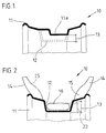
- FIG. 1 shows a one-piece rim 11 of a vehicle wheel 10 with an asymmetrical rim bed 11a.
- a symmetrical rim well 12 is shown with dashed lines, the recess 13 of which is formed deeper than the asymmetrical rim well 11a.
- a tire 14 shown in the following figures can be mounted on the rim 11.
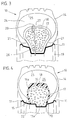
- a tubular inner tire 16 can be inserted into the depression 13 of the rim well 12 in the depressurized state, as shown in FIG. 2.
- the inner tire 16 which is designed here as a closed tube, is stretched and pulled over one of the rim flanges 19 of the rim 11.
- it consists of stretchable rubber or another suitable elastomer.
- the tubular inner tire 16 is foamed with a foam filling 17.
- a foam filling 17 This creates a vehicle wheel 10, in the tire interior 24 of which an elastic, load-bearing support body in the form of foam filling 17 is arranged for emergency operation.
- the foam filling should be largely thermally stable and, when heated, should not have any increasing flexibility and should retain its shape and stability.
- the tire 14 can deflect without touching the tread 20 of the tubular inner tire 16.
- the foam filling 17 should have a load capacity that is large enough to To keep the vehicle drivable in the event of pressure loss or destruction of the tire 14.
- the tubular inner tire 16 can be provided in the area of its tread 20 with a reinforcement 18 in the form of conventional fabric inserts.
- This strength member 18 has a circumferential length that is greater than the circumferential length of a rim flange 19.
- the tubular inner tire 16 is dimensioned in the expanded state so that it lies in the area of the tire beads 15 with lateral bead supports 21 on the inner wall 25 of the tire 14.
- the tire 14 is thereby securely held on the rim 11 even in the damaged state.
- a rim 11 with an asymmetrical rim bed 11a is used.
- a semi-tubular inner tire 16a is provided as emergency run support, which is vulcanized to the tire inner wall 25 with vulcanizations 22 in the area of the tire beads 15.
- the semi-tubular inner tire 16a is initially not foamed.
- the semi-tubular inner tire 16a can be inserted into the tire interior 24 and the tire 14 can be pulled over one of the rim flanges 19 of the rim 11.
- the foam filling 17 is foamed between the semi-tubular inner tire 16a and the rim 11.
- the radially outer tread 20 of the tubular inner tire 16a can be provided with a reinforcement 18.
- Such a tire is used for disassembly 14 cut from the rim 11, since it is then destroyed anyway.
- the semi-tubular inner tire 16a is provided with a double wall 28.
- the foam filling 17 is foamed into the space 17a between the semi-tubular inner tire 16a and the double wall 28. This avoids contact with the rim 11 and possible adhesion.
- the foam filling 17 is load-bearing and stabilizes the tire beads 15 in their intended position on the rim 11.
- a lubricant is introduced into the tire interior 24. It is preferably brushed onto the tread 20 of the inner tire 16 or 16a before the tire 14 is installed. This is intended to reduce the friction between the inner wall 25 of the tire and the inner tire 16 or 16a.
- the lubricant can also be provided in a lubricant container 27, as is shown schematically in FIG. 3.
- This lubricant container 27 is destroyed when the tire 14 is damaged and the tire loses its supporting air pressure, and the lubricant is released.
- valve tube 26 is guided through the foam filling 17 and the inner tire 16 or 16a.
- This valve tube 26 is flexible and can follow possible relative movements between the tire 14 and the inner tire 16 or 16a.
- the height of the inner tire 16 or 16a has about 50-70% of the cross-sectional height of the tire 14 in the foamed state. As a result, a sufficiently large deflection is always possible when the vehicle wheel 10 is in operation with the tire 14 intact.
Landscapes
- Engineering & Computer Science (AREA)
- Mechanical Engineering (AREA)
- Tires In General (AREA)
Applications Claiming Priority (2)
| Application Number | Priority Date | Filing Date | Title |
|---|---|---|---|
| DE19516512A DE19516512A1 (de) | 1995-05-05 | 1995-05-05 | Kraftfahrzeug-Luftreifen mit eingelegtem Notlaufstützkörper |
| DE19516512 | 1995-05-05 |
Publications (1)
| Publication Number | Publication Date |
|---|---|
| EP0748706A2 true EP0748706A2 (fr) | 1996-12-18 |
Family
ID=7761157
Family Applications (1)
| Application Number | Title | Priority Date | Filing Date |
|---|---|---|---|
| EP96106940A Withdrawn EP0748706A2 (fr) | 1995-05-05 | 1996-05-02 | Bandage pneumatique pour véhicule automobile, doté d'un support de sécurité |
Country Status (2)
| Country | Link |
|---|---|
| EP (1) | EP0748706A2 (fr) |
| DE (1) | DE19516512A1 (fr) |
Cited By (1)
| Publication number | Priority date | Publication date | Assignee | Title |
|---|---|---|---|---|
| DE102006037095A1 (de) * | 2006-08-07 | 2008-02-14 | Heiner Ellinger | Notlaufradvorrichtung |
Families Citing this family (1)
| Publication number | Priority date | Publication date | Assignee | Title |
|---|---|---|---|---|
| CN109094300A (zh) * | 2017-06-21 | 2018-12-28 | 韩剑 | 一种车轮辅助支撑内胎 |
Family Cites Families (2)
| Publication number | Priority date | Publication date | Assignee | Title |
|---|---|---|---|---|
| BE556144A (fr) * | 1956-03-27 | |||
| US4751951A (en) * | 1983-09-14 | 1988-06-21 | The Goodyear Tire & Rubber Company | Safety support system for a tubeless tire |
-
1995
- 1995-05-05 DE DE19516512A patent/DE19516512A1/de not_active Withdrawn
-
1996
- 1996-05-02 EP EP96106940A patent/EP0748706A2/fr not_active Withdrawn
Cited By (1)
| Publication number | Priority date | Publication date | Assignee | Title |
|---|---|---|---|---|
| DE102006037095A1 (de) * | 2006-08-07 | 2008-02-14 | Heiner Ellinger | Notlaufradvorrichtung |
Also Published As
| Publication number | Publication date |
|---|---|
| DE19516512A1 (de) | 1996-11-07 |
Similar Documents
| Publication | Publication Date | Title |
|---|---|---|
| DE102004055892B4 (de) | Speichenradfelge für Schlauchlosreifen | |
| WO1999064260A1 (fr) | Roue de vehicule automobile comportant un corps d'appui pour roulement de secours | |
| DE3433318A1 (de) | Verfahren zum aufpumpen von luftreifen und luftreifen fuer das verfahren | |
| DE7238963U (de) | Kugelsicherer reifen | |
| DE2653658A1 (de) | Fahrzeugluftreifen mit plattfahreigenschaften | |
| DE3101408A1 (de) | Fahrzeugreifen | |
| DE3102614A1 (de) | Radialreifen-karkasse und verfahren zu ihrer herstellung | |
| DE1001139B (de) | Schlauchloser Luftreifen | |
| DE2922985C2 (fr) | ||
| EP1069996B1 (fr) | Roue de vehicule, notamment dotee d'une jante d'une seule piece et d'un pneumatique sans chambre a air, appropriee a une utilisation en cas d'urgence, et procede de montage d'une telle roue | |
| DE69617018T2 (de) | Vollreifen und verfahren zur herstellung | |
| DE2850973C2 (fr) | ||
| DE3704798A1 (de) | Fahrzeugrad | |
| DE3804505A1 (de) | Luftbereiftes fahrzeugrad | |
| DE19837712A1 (de) | Fahrzeugrad | |
| DE19516512A1 (de) | Kraftfahrzeug-Luftreifen mit eingelegtem Notlaufstützkörper | |
| EP0418762A1 (fr) | Roue de véhicule à pneumatique | |
| EP0148338A2 (fr) | Roue de véhicule automobile | |
| DE102006037095A1 (de) | Notlaufradvorrichtung | |
| DE10133534C1 (de) | Fahrzeugrad mit einem Notlaufstützkörper | |
| DE4428516A1 (de) | Fahrzeugreifen | |
| DE2356097A1 (de) | Vorrichtung zum verspannen eines luftreifens auf seiner felge | |
| EP1066986B1 (fr) | Jante d'une roue de véhicule pour pneumatiques sans chambre à air avec surface d'appui de sécurité sur la partie radiale extérieure de la surface cylindrique de la jante | |
| DE2418751A1 (de) | Fahrzeugfelge fuer schlauchlose luftreifen, insbesondere guertelreifen | |
| DE8702348U1 (de) | Fahrzeugrad |
Legal Events
| Date | Code | Title | Description |
|---|---|---|---|
| PUAI | Public reference made under article 153(3) epc to a published international application that has entered the european phase |
Free format text: ORIGINAL CODE: 0009012 |
|
| STAA | Information on the status of an ep patent application or granted ep patent |
Free format text: STATUS: THE APPLICATION HAS BEEN WITHDRAWN |
|
| AK | Designated contracting states |
Kind code of ref document: A2 Designated state(s): DE FR GB IT |
|
| 18W | Application withdrawn |
Withdrawal date: 19961108 |