EP0748712A1 - Réservoir de carburant pour véhicules automobiles - Google Patents
Réservoir de carburant pour véhicules automobiles Download PDFInfo
- Publication number
- EP0748712A1 EP0748712A1 EP96108987A EP96108987A EP0748712A1 EP 0748712 A1 EP0748712 A1 EP 0748712A1 EP 96108987 A EP96108987 A EP 96108987A EP 96108987 A EP96108987 A EP 96108987A EP 0748712 A1 EP0748712 A1 EP 0748712A1
- Authority
- EP
- European Patent Office
- Prior art keywords
- filler
- fuel
- tank
- electrically
- motor
- Prior art date
- Legal status (The legal status is an assumption and is not a legal conclusion. Google has not performed a legal analysis and makes no representation as to the accuracy of the status listed.)
- Withdrawn
Links
- 239000002828 fuel tank Substances 0.000 title claims description 7
- 239000000945 filler Substances 0.000 claims abstract description 44
- 239000000463 material Substances 0.000 claims abstract description 15
- 239000002184 metal Substances 0.000 claims abstract description 15
- 239000000446 fuel Substances 0.000 claims abstract description 11
- 239000004033 plastic Substances 0.000 claims abstract description 11
- 229920003023 plastic Polymers 0.000 claims abstract description 11
- 239000012777 electrically insulating material Substances 0.000 claims abstract description 4
- 239000000203 mixture Substances 0.000 description 4
- 239000000243 solution Substances 0.000 description 4
- 238000010276 construction Methods 0.000 description 3
- 239000004020 conductor Substances 0.000 description 2
- 239000013536 elastomeric material Substances 0.000 description 2
- 238000004880 explosion Methods 0.000 description 2
- 230000006698 induction Effects 0.000 description 2
- 238000002347 injection Methods 0.000 description 2
- 239000007924 injection Substances 0.000 description 2
- 238000005299 abrasion Methods 0.000 description 1
- 239000008186 active pharmaceutical agent Substances 0.000 description 1
- 238000010586 diagram Methods 0.000 description 1
- 230000008020 evaporation Effects 0.000 description 1
- 238000001704 evaporation Methods 0.000 description 1
- 239000007788 liquid Substances 0.000 description 1
- 238000007789 sealing Methods 0.000 description 1
Images

Classifications
-
- B—PERFORMING OPERATIONS; TRANSPORTING
- B60—VEHICLES IN GENERAL
- B60R—VEHICLES, VEHICLE FITTINGS, OR VEHICLE PARTS, NOT OTHERWISE PROVIDED FOR
- B60R16/00—Electric or fluid circuits specially adapted for vehicles and not otherwise provided for; Arrangement of elements of electric or fluid circuits specially adapted for vehicles and not otherwise provided for
- B60R16/02—Electric or fluid circuits specially adapted for vehicles and not otherwise provided for; Arrangement of elements of electric or fluid circuits specially adapted for vehicles and not otherwise provided for electric constitutive elements
- B60R16/06—Electric or fluid circuits specially adapted for vehicles and not otherwise provided for; Arrangement of elements of electric or fluid circuits specially adapted for vehicles and not otherwise provided for electric constitutive elements for removing electrostatic charges
-
- B—PERFORMING OPERATIONS; TRANSPORTING
- B60—VEHICLES IN GENERAL
- B60K—ARRANGEMENT OR MOUNTING OF PROPULSION UNITS OR OF TRANSMISSIONS IN VEHICLES; ARRANGEMENT OR MOUNTING OF PLURAL DIVERSE PRIME-MOVERS IN VEHICLES; AUXILIARY DRIVES FOR VEHICLES; INSTRUMENTATION OR DASHBOARDS FOR VEHICLES; ARRANGEMENTS IN CONNECTION WITH COOLING, AIR INTAKE, GAS EXHAUST OR FUEL SUPPLY OF PROPULSION UNITS IN VEHICLES
- B60K15/00—Arrangement in connection with fuel supply of combustion engines or other fuel consuming energy converters, e.g. fuel cells; Mounting or construction of fuel tanks
- B60K15/03—Fuel tanks
- B60K15/04—Tank inlets
-
- B—PERFORMING OPERATIONS; TRANSPORTING
- B60—VEHICLES IN GENERAL
- B60K—ARRANGEMENT OR MOUNTING OF PROPULSION UNITS OR OF TRANSMISSIONS IN VEHICLES; ARRANGEMENT OR MOUNTING OF PLURAL DIVERSE PRIME-MOVERS IN VEHICLES; AUXILIARY DRIVES FOR VEHICLES; INSTRUMENTATION OR DASHBOARDS FOR VEHICLES; ARRANGEMENTS IN CONNECTION WITH COOLING, AIR INTAKE, GAS EXHAUST OR FUEL SUPPLY OF PROPULSION UNITS IN VEHICLES
- B60K15/00—Arrangement in connection with fuel supply of combustion engines or other fuel consuming energy converters, e.g. fuel cells; Mounting or construction of fuel tanks
- B60K15/03—Fuel tanks
- B60K2015/03328—Arrangements or special measures related to fuel tanks or fuel handling
- B60K2015/03381—Arrangements or special measures related to fuel tanks or fuel handling for preventing explosions
-
- B—PERFORMING OPERATIONS; TRANSPORTING
- B60—VEHICLES IN GENERAL
- B60K—ARRANGEMENT OR MOUNTING OF PROPULSION UNITS OR OF TRANSMISSIONS IN VEHICLES; ARRANGEMENT OR MOUNTING OF PLURAL DIVERSE PRIME-MOVERS IN VEHICLES; AUXILIARY DRIVES FOR VEHICLES; INSTRUMENTATION OR DASHBOARDS FOR VEHICLES; ARRANGEMENTS IN CONNECTION WITH COOLING, AIR INTAKE, GAS EXHAUST OR FUEL SUPPLY OF PROPULSION UNITS IN VEHICLES
- B60K15/00—Arrangement in connection with fuel supply of combustion engines or other fuel consuming energy converters, e.g. fuel cells; Mounting or construction of fuel tanks
- B60K15/03—Fuel tanks
- B60K2015/03328—Arrangements or special measures related to fuel tanks or fuel handling
- B60K2015/03401—Arrangements or special measures related to fuel tanks or fuel handling for preventing electrostatic charges
Definitions
- the present invention relates to a fuel tank for motor vehicles.
- the subject of the invention is a fuel tank comprising a container having a filler pipe with an end filler of electrically-insulating material which, when the tank is in the fitted condition, is fixed by fixing means in a hole provided in a sheet-metal element of the body of the motor vehicle and can house the end nozzle of a metal gun for supplying the fuel at a filling station.
- a potential difference is therefore generated between the supply gun and the motor vehicle and, in the worst case, is equal to the sum of the potential difference between the tank and the earth and the potential difference between the supply gun and the earth.
- the object of the present invention is to provide a solution to the problem described above which is simpler than known solutions from the point of view of its construction and implementation.
- a fuel tank of the type specified above characterized in that at least a portion of the filler which is intended to contact the end nozzle of a fuel-supply gun is made of an electrically-conductive plastics material, the said portion of the filler being connected to the fixing means which are made at least partly of an electrically-conductive polymeric material so that, when the tank is in the fitted condition, the said portion of the filler is connected electrically to the motor-vehicle body, the said portion of the filler and the associated fixing means being formed in a manner such that, when the nozzle of a fuel-supply gun is inserted in and is in contact with the said portion of the filler, the electrical resistance between the nozzle and the motor-vehicle bodywork is substantially equal to or less than 100 Mohms.
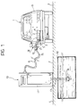
- a motor vehicle particularly a motor car, generally indicated 1
- the tank comprises a container 4 of electrically-insulating material, particularly plastics material, forming a filler pipe 5 with an end filler 6 ( Figure 2).
- the filler 6 is fixed in a hole 7 ( Figure 2) provided in a sheet-metal element 8 of the motor-vehicle body 9.
- Figure 1 also shows schematically a filling station 10.
- the station comprises a pillar 11 connected to an underground tank 12 by means of a suction pipe 13 which is associated, in known manner, with a submerged pump 14.
- the fuel 3 drawn from the underground tank 12 is supplied to the tank 4 of the motor vehicle 1 through a hose 15 connected to the pillar 11 and made, for example, of elastomeric material.
- a metal fuel-supply gun 16 is connected to the distal end of this hose 15, in known manner. This gun has at its end a nozzle 17 which is inserted in the filler 6 of the vehicle tank 4 (see also Figure 2).
- V vp V vt + V tp
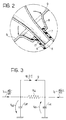
- Sparks may then be struck between the fuel-supply gun and the motor-vehicle body 9, as indicated symbolically by the serrated arrows in Figure 2 and, in the presence of an air/petrol-vapour mixture may lead to a fire/explosion in the region adjacent the filler 6 of the vehicle tank.
- Figure 3 shows a simplified electrical model of the phenomena described above; the supply gun 16 and, in particular, its nozzle 17, and the bodywork 9 together form a kind of discharger or spark gap.
- the filler of the motor-vehicle tank 4 is formed and is connected to the bodywork 9 of the motor vehicle in a manner such that the electrical resistance between the nozzle of a fuel-supply gun and the bodywork of the motor vehicle during a filling-up operation is substantially equal to or less than 100 Mohms.
- At least a portion of the filler 6 of the motor-vehicle tank 4 which is intended to contact the end nozzle 17 of a fuel-supply gun 16 is made of an electrically-conductive plastics material. This portion of the filler 6 is then connected to the bodywork 9 of the motor vehicle by means of fixing devices which are at least partly made of an electrically-conductive polymeric material so that, when the tank 4 is in the fitted condition, the electrically-conductive portion of the filler 6 is connected electrically to the motor-vehicle body 9.
- the resistivity of the electrically-conductive plastics/polymeric materials used and the geometrical shapes of the electrically conductive portion of the filler 6 and of the associated means for fixing to the body are designed, by known criteria, in a manner such that, when the nozzle of a fuel-supply gun is inserted in and in contact with the electrically-conductive portion of the filler, the electrical resistance between the nozzle and the motor-vehicle bodywork is substantially equal to or less than 100 Mohms.
- Figure 4 shows a first embodiment in which the filler 6 of the tank 4 is made entirely of an electrically-conductive plastics material.
- the end portion of this filler has a pair of integral tabs 6a also of electrically-conductive plastics material, for the fixing of the filler in the hole 7 in the motor-vehicle body 9 by means of screws 18 of conductive material.
- a kind of plate valve may be provided in the filler 6 of the tank 4 (as is now usual in the most recent motor cars), the valve including a tubular element 19 fixed in the filler and having a frusto-conical portion 19a the end rim of which acts as a valve seat with which a plate obturator 20 articulated to the wall of the filler 6 at 21 can cooperate.
- the tubular element 19 and the plate obturator 20 are advantageously also made of an electrically-conductive plastics material.
- the end of the filler 6 may have an integral internal annular projection 22, also of electrically-conductive plastics material, which is intended to contact the end nozzle of the fuel-supply gun.
- the filler 6 of the tank 4 is also made of electrically-conductive plastics material and is fixed in the hole 7 provided in the motor-vehicle bodywork 9 by means of a frusto-conical connector element 23.
- This connector is conveniently made of an electrically-conductive elastomeric material and, in the embodiment shown by way of example, is fixed in the hole 7 in the body 9 by means of pins 24 or similar fixing devices made of electrically-conductive material.
- the tapered end of the connector 23 is force-fitted on the end of the filler.
- a plate valve of the type already described above with reference to Figure 4 may also be provided in the embodiment of Figure 5.
Landscapes
- Engineering & Computer Science (AREA)
- Mechanical Engineering (AREA)
- Life Sciences & Earth Sciences (AREA)
- Sustainable Development (AREA)
- Sustainable Energy (AREA)
- Chemical & Material Sciences (AREA)
- Combustion & Propulsion (AREA)
- Transportation (AREA)
- Cooling, Air Intake And Gas Exhaust, And Fuel Tank Arrangements In Propulsion Units (AREA)
Applications Claiming Priority (2)
| Application Number | Priority Date | Filing Date | Title |
|---|---|---|---|
| ITTO950496 | 1995-06-14 | ||
| IT95TO000496A IT1276384B1 (it) | 1995-06-14 | 1995-06-14 | Serbatorio per il carburante per autoveicoli |
Publications (1)
| Publication Number | Publication Date |
|---|---|
| EP0748712A1 true EP0748712A1 (fr) | 1996-12-18 |
Family
ID=11413645
Family Applications (1)
| Application Number | Title | Priority Date | Filing Date |
|---|---|---|---|
| EP96108987A Withdrawn EP0748712A1 (fr) | 1995-06-14 | 1996-06-05 | Réservoir de carburant pour véhicules automobiles |
Country Status (2)
| Country | Link |
|---|---|
| EP (1) | EP0748712A1 (fr) |
| IT (1) | IT1276384B1 (fr) |
Cited By (11)
| Publication number | Priority date | Publication date | Assignee | Title |
|---|---|---|---|---|
| FR2759032A1 (fr) * | 1997-02-05 | 1998-08-07 | Journee Paul Sa | Dispositif de remplissage d'un reservoir de carburant pour vehicule automobile comportant des moyens perfectionnes de mise a la masse electrique |
| EP0887219A1 (fr) * | 1997-06-27 | 1998-12-30 | Mecrom Ott U. Holey OHG | Bouchon à fermeture automatique pour réservoir de carburant spécialement adapté au remplissage automatisé |
| FR2772679A1 (fr) * | 1997-12-23 | 1999-06-25 | Journee Paul Sa | Dispositif de remplissage d'un reservoir de vehicule automobile mis a la masse dans la zone d'arrivee en contact du flux de carburant |
| US6508374B1 (en) * | 1999-11-04 | 2003-01-21 | Stant Manufacturing Inc. | Filler neck closure with static charge dissipater |
| US7163117B2 (en) | 2002-05-01 | 2007-01-16 | Stant Manufacturing Inc. | Static charge dissipater for filler neck closure |
| CN100360333C (zh) * | 2002-06-05 | 2008-01-09 | 考特克斯·特克斯罗恩有限公司及两合公司 | 注入管 |
| EP1705052A3 (fr) * | 2005-03-25 | 2009-04-29 | Eaton Corporation | Component de réservoir de carburant à connecteur soudable |
| CN105711525A (zh) * | 2014-12-02 | 2016-06-29 | 上海亚大汽车塑料制品有限公司 | 导电加油管总成 |
| CN111285322A (zh) * | 2020-02-14 | 2020-06-16 | 吴凡 | 一种防爆加油枪 |
| CN111347871A (zh) * | 2020-02-14 | 2020-06-30 | 吴凡 | 一种防爆油箱嘴 |
| CN114080354A (zh) * | 2019-04-30 | 2022-02-22 | B和T产品有限公司 | 燃料容器 |
Citations (3)
| Publication number | Priority date | Publication date | Assignee | Title |
|---|---|---|---|---|
| JPS6291317A (ja) * | 1985-10-18 | 1987-04-25 | Showa Denko Kk | 合成樹脂製フイラ−パイプ |
| US4946060A (en) * | 1989-07-31 | 1990-08-07 | General Motors Corporation | Seal assembly for vehicle filler neck |
| GB2255554A (en) * | 1991-05-03 | 1992-11-11 | Italiana Serrature Torino | Vehicle fuel tank feed pipe with vent pipe |
-
1995
- 1995-06-14 IT IT95TO000496A patent/IT1276384B1/it active IP Right Grant
-
1996
- 1996-06-05 EP EP96108987A patent/EP0748712A1/fr not_active Withdrawn
Patent Citations (3)
| Publication number | Priority date | Publication date | Assignee | Title |
|---|---|---|---|---|
| JPS6291317A (ja) * | 1985-10-18 | 1987-04-25 | Showa Denko Kk | 合成樹脂製フイラ−パイプ |
| US4946060A (en) * | 1989-07-31 | 1990-08-07 | General Motors Corporation | Seal assembly for vehicle filler neck |
| GB2255554A (en) * | 1991-05-03 | 1992-11-11 | Italiana Serrature Torino | Vehicle fuel tank feed pipe with vent pipe |
Non-Patent Citations (1)
| Title |
|---|
| PATENT ABSTRACTS OF JAPAN vol. 011, no. 301 (M - 628) 30 September 1987 (1987-09-30) * |
Cited By (12)
| Publication number | Priority date | Publication date | Assignee | Title |
|---|---|---|---|---|
| FR2759032A1 (fr) * | 1997-02-05 | 1998-08-07 | Journee Paul Sa | Dispositif de remplissage d'un reservoir de carburant pour vehicule automobile comportant des moyens perfectionnes de mise a la masse electrique |
| EP0857602A1 (fr) * | 1997-02-05 | 1998-08-12 | Paul Journee S.A. | Dispositif de remplissage d'un réservoir de carburant de véhicule automobile comportant des moyens perfectionnés de mise à la masse électrique |
| EP0887219A1 (fr) * | 1997-06-27 | 1998-12-30 | Mecrom Ott U. Holey OHG | Bouchon à fermeture automatique pour réservoir de carburant spécialement adapté au remplissage automatisé |
| FR2772679A1 (fr) * | 1997-12-23 | 1999-06-25 | Journee Paul Sa | Dispositif de remplissage d'un reservoir de vehicule automobile mis a la masse dans la zone d'arrivee en contact du flux de carburant |
| US6508374B1 (en) * | 1999-11-04 | 2003-01-21 | Stant Manufacturing Inc. | Filler neck closure with static charge dissipater |
| US7163117B2 (en) | 2002-05-01 | 2007-01-16 | Stant Manufacturing Inc. | Static charge dissipater for filler neck closure |
| CN100360333C (zh) * | 2002-06-05 | 2008-01-09 | 考特克斯·特克斯罗恩有限公司及两合公司 | 注入管 |
| EP1705052A3 (fr) * | 2005-03-25 | 2009-04-29 | Eaton Corporation | Component de réservoir de carburant à connecteur soudable |
| CN105711525A (zh) * | 2014-12-02 | 2016-06-29 | 上海亚大汽车塑料制品有限公司 | 导电加油管总成 |
| CN114080354A (zh) * | 2019-04-30 | 2022-02-22 | B和T产品有限公司 | 燃料容器 |
| CN111285322A (zh) * | 2020-02-14 | 2020-06-16 | 吴凡 | 一种防爆加油枪 |
| CN111347871A (zh) * | 2020-02-14 | 2020-06-30 | 吴凡 | 一种防爆油箱嘴 |
Also Published As
| Publication number | Publication date |
|---|---|
| ITTO950496A1 (it) | 1996-12-14 |
| ITTO950496A0 (it) | 1995-06-14 |
| IT1276384B1 (it) | 1997-10-31 |
Similar Documents
| Publication | Publication Date | Title |
|---|---|---|
| EP0748712A1 (fr) | Réservoir de carburant pour véhicules automobiles | |
| AU642616B2 (en) | Electrostatically dissipative fuel filter | |
| US20020124833A1 (en) | Fuel supply system | |
| US6094121A (en) | Engine igniting coil device | |
| US4358135A (en) | Connector for igniting circuit of priming device | |
| US20120234172A1 (en) | Fine particle sensor and mounting structure therefor | |
| US7168416B2 (en) | Multi-point grounding plate for fuel pump module | |
| US7715169B2 (en) | Fuel receptacle isolation system for reducing the possibility of static discharge during the refill of high pressure storage tanks in motor vehicles | |
| US7040298B2 (en) | Grounding structure of fuel tank | |
| US8435058B2 (en) | Coupling element for hydraulic lines | |
| US8123198B2 (en) | Ignition system for a pulse fog generator | |
| US2958843A (en) | Static grounding connection | |
| US4540191A (en) | Static discharge prevention system for a largely non-metallic fuel tank | |
| KR101028669B1 (ko) | 접지 구조를 구비한 통전 플라스틱 필러넥 | |
| US20060260712A1 (en) | Static dissipative fuel dispensing nozzel | |
| AU2003229520A1 (en) | Filler tube | |
| KR100530122B1 (ko) | 차량 연료 주입구 캡의 정전기 방지 장치 | |
| GB2273742A (en) | Treatment of engine air and/or fuel charge. | |
| Nabours | Static discharge hazard during refueling at retail gasoline stations | |
| US4390759A (en) | Tilt-sensitive ignition switch | |
| JPS6154678B2 (fr) | ||
| US4543710A (en) | Method of reducing corona discharge in an electrostatic spray gun | |
| US2291237A (en) | Switch | |
| EP1661826A1 (fr) | Tuyaux de remplissage mis à la masse | |
| KR0152513B1 (ko) | Lpg용 자동차의 연료 잔량 경보 장치 |
Legal Events
| Date | Code | Title | Description |
|---|---|---|---|
| PUAI | Public reference made under article 153(3) epc to a published international application that has entered the european phase |
Free format text: ORIGINAL CODE: 0009012 |
|
| AK | Designated contracting states |
Kind code of ref document: A1 Designated state(s): DE ES FR GB SE |
|
| 17P | Request for examination filed |
Effective date: 19970606 |
|
| 17Q | First examination report despatched |
Effective date: 19980922 |
|
| STAA | Information on the status of an ep patent application or granted ep patent |
Free format text: STATUS: THE APPLICATION IS DEEMED TO BE WITHDRAWN |
|
| 18D | Application deemed to be withdrawn |
Effective date: 19990407 |