EP0748773B1 - Procédé de régulation du chauffage d'un four à cuve de fusion de verre - Google Patents
Procédé de régulation du chauffage d'un four à cuve de fusion de verre Download PDFInfo
- Publication number
- EP0748773B1 EP0748773B1 EP96108994A EP96108994A EP0748773B1 EP 0748773 B1 EP0748773 B1 EP 0748773B1 EP 96108994 A EP96108994 A EP 96108994A EP 96108994 A EP96108994 A EP 96108994A EP 0748773 B1 EP0748773 B1 EP 0748773B1
- Authority
- EP
- European Patent Office
- Prior art keywords
- furnace
- glass
- heat
- melt
- glass melt
- Prior art date
- Legal status (The legal status is an assumption and is not a legal conclusion. Google has not performed a legal analysis and makes no representation as to the accuracy of the status listed.)
- Expired - Lifetime
Links
Images

Classifications
-
- C—CHEMISTRY; METALLURGY
- C03—GLASS; MINERAL OR SLAG WOOL
- C03B—MANUFACTURE, SHAPING, OR SUPPLEMENTARY PROCESSES
- C03B5/00—Melting in furnaces; Furnaces so far as specially adapted for glass manufacture
- C03B5/16—Special features of the melting process; Auxiliary means specially adapted for glass-melting furnaces
- C03B5/24—Automatically regulating the melting process
-
- C—CHEMISTRY; METALLURGY
- C03—GLASS; MINERAL OR SLAG WOOL
- C03B—MANUFACTURE, SHAPING, OR SUPPLEMENTARY PROCESSES
- C03B5/00—Melting in furnaces; Furnaces so far as specially adapted for glass manufacture
- C03B5/02—Melting in furnaces; Furnaces so far as specially adapted for glass manufacture in electric furnaces, e.g. by dielectric heating
- C03B5/027—Melting in furnaces; Furnaces so far as specially adapted for glass manufacture in electric furnaces, e.g. by dielectric heating by passing an electric current between electrodes immersed in the glass bath, i.e. by direct resistance heating
- C03B5/03—Tank furnaces
-
- C—CHEMISTRY; METALLURGY
- C03—GLASS; MINERAL OR SLAG WOOL
- C03B—MANUFACTURE, SHAPING, OR SUPPLEMENTARY PROCESSES
- C03B5/00—Melting in furnaces; Furnaces so far as specially adapted for glass manufacture
- C03B5/16—Special features of the melting process; Auxiliary means specially adapted for glass-melting furnaces
- C03B5/235—Heating the glass
Definitions
- the invention relates to a method for controlling the heating of glass tub furnaces with an upper furnace and a lower furnace, in which made of charging material a glass melt is formed with a melt mirror and from it is withdrawn with at least one burner assigned to the upper furnace, through which an amount of energy required for melting is introduced, where temperatures and quantities of fuel, combustion air and feed material and heat quantities of the glass melt can be determined.
- Both the charging material and the glass melt formed from it are problematic substances.
- the melting behavior of the initially on the glass melt floating charging material is very strong from its composition dependent.
- the charging material tends to foam and has poor thermal conductivity.
- the glass melt itself also has an unfavorable one Thermal conductivity, leading to the formation of temperature gradients and viscosity differences and thus to differently distributed flow velocities leads. It is particularly problematic that the Heat requirement of the glass melt located in the lower furnace, in the so-called basin through the heat transport through the melt level must be covered if heating electrodes are not provided in the lower furnace, that have to be supplied with electrical energy. The following result from this Problems known to experts:
- Periodic fluctuations of disturbance variables such as the amount of cullet and cullet quality and withdrawal quantity can take several days fluctuate so that their effects can add up over days, which makes it extremely difficult to adjust them with conventional controllers.
- An essential disruptive factor for the operation of the tub is the foam formation on the glass bath surface, which occurs under certain conditions.
- the foam formation depends on the batch composition, on the ratio of batch / cullet and on the ratio of the different cullets to one another or their SO 3 content. Glasses with different SO 3 contents react with each other to form foam during melting.
- the high recycling rates, particularly in the case of hollow glass, have led to the use of mixed shards of various origins, the foam formation potential of which cannot be predicted.
- the foam formation due to the redox conditions in both Batch as well as affected in the flame i.e., any change in the ratio Fuel / air and the flame position above the melt level leads to different foaming.
- This one that occurs on the melt level Foam insulates the glass melt from the flame radiation, so that the heat flow density from the upper furnace into the lower furnace as well as into the glass melt is subject to constant fluctuations.
- Measurements of the glass bath temperature in the furnace are of no use Results because the required temperature sensors are only on the bottom of the Basins can be installed.
- a change in heat transport due to the melt level leads to a temperature change after hours at the bottom of the pool and only after hours of regular intervention.
- the foam conditions can change after hours have changed again fundamentally, so that a temperature control that on Temperature sensors in the glass melt based on a rocking of the Control behavior leads.
- the procedure is such that the The amount of energy supplied to the furnace is chosen so high that even when Occurrence of foam on the glass bath surface due to heat transfer this remains high enough to guarantee the required quality of the glass.
- This procedure leads on the one hand to a higher energy consumption than is theoretically necessary would be, and on the other hand to constantly changing temperatures in the inlet the work tub or the distribution channel, which regulates the temperature deviations in the work tub, in the distribution channel and in the forehearth is made significantly more difficult.
- tubs or basins to be equipped with additional electrical heating, since the electrical energy with an efficiency of almost 100% via heating electrodes in the glass melt can be initiated. With such additional heaters it is possible to maintain the minimum temperatures leading to acceptable quality of the glass.
- the electrical energy is much more expensive than that is fossil energy, such a mode of operation of a glass bath furnace very expensive.
- the invention is therefore based on the object of a control method at the outset described genus to improve that the thermal Efficiency of the entire system improved, but also the glass quality constant at the outlet of the tub or basin within narrow limits can be held.
- the relevant data or parameters are available at any time, and either by calculation and / or measurement, the measurements can be carried out either continuously or at short intervals, quasi-continuously. From this, heat balances can be created for the whole Oven, for the upper oven on the one hand and for the lower oven on the other create. Due to the high computer speeds of a normal one PCs the value of the actual value deviation from the setpoint is constantly available and can be used extremely briefly to regulate the amount of energy, and both to regulate the amount of fossil energy and, if necessary of electrical energy to the furnace. Since the measured values mentioned The exact heat flow from the upper furnace is always available without delay Known to the furnace through the melt level and can be delayed in the direction of the setpoint. The melt level is, so to speak, the reference level for the heat flow. The difference is the control deviation between the two values.
- the said total heat balance provides information about the sum of the wall, Cooling and leakage losses. From the sum of the total wall, cooling and Leakage losses are then subtracted from the sub-furnace losses.
- the losses of the sub-oven are pure wall and cooling losses and due to proportionality stable temperatures almost constant, also their percentage Share of total losses relatively low. In the event of deviations in the outside wall temperature of the sub-furnace and / or the ambient air becomes their value corrected. Leakage losses do not occur in the lower furnace.
- the wall, cooling and possibly leakage losses determined in this way are in each case used in a heat balance calculation of the upper furnace and the lower furnace.
- the heat flow from the upper furnace can now be calculated from the upper furnace balance is introduced into the glass bath by the melt level, exactly determined as shown above.
- This heat flow is now calculated from the heat balance using a calculated setpoint of the sub-furnace, which is based on the throughput, the batch composition, from the cullet and batch ratio the wall losses of the sub-furnace and from the target temperature of the glass melt at the culvert results, if applicable, minus that in the lower furnace fed electrical energy.
- the endothermic energy value i.e. the amount of energy required to dissociate the Carbonates and needed for silicate formation are also determined.
- Another advantage of the control method according to the invention is optimization the ratio between the electrical energy fed into the Glass melt and the burner heating of the upper furnace with fossil fuels from a cost perspective.
- the feeding of electrical energy into the glass bath takes place with an efficiency of almost 100%, minus the Cooling losses for the electrode holder, so that depending on the amount of energy fed with an energy efficiency of 95 to 98% for electric heating can be expected.
- the economy of the burner heating in the upper furnace is determined by the combustion technology Efficiency determined. If to increase the heat flow to the required level higher costs by increasing the amount of fuel arise as a result of feeding the energy through electricity into the Unterofen, it is cheaper to increase the amount of electrical energy and the To keep the amount of fuel constant and vice versa.
- the cost of electricity and heating gas in a calculator entered it is able at any time using suitable software to the optimal ratio between the firing of the furnace Gas and feeding electrical energy into the furnace.
- This type of control can also be performed by the process controller mentioned be carried out.
- the case described can well occur if very high furnace loads are required, for example at maximum load of the tub or when there is a lot of foam on the glass bath arose, which cannot be removed.
- Another advantage of the subject of the invention is that the glass quality can be determined more precisely than with the known control methods was possible.
- Melting glass is a process of time and temperature. Both Known processes are usually neither the residence time nor the temperatures to keep constant. With the control method according to the invention and keeping the heat flow constant during operation, that the glass bath temperatures remain absolutely constant on average, i.e. that at constant throughput a constant quality is achieved. In case of changes of the throughput naturally changes the average residence time of the glass in the system, whereby the ratio between minimum dwell time to average dwell time with one and the same tub relative remains constant.
- the mean residence time which results from the volume of the basin and the volume passed per unit of time in relation to the heat flow is set, it is possible to have a shorter dwell time by a higher one To compensate for heat flow so that even with changing throughputs the tub by taking into account changes in heat flow the mean dwell time the same quality as with other tub loads can be maintained.
- the method according to the invention can also be used with glass melting tanks use multiple zones. If the intermediate temperatures between the Zones in the superstructure as well as in the basin area are known or relative can be estimated precisely, it is quite possible, the inventive Use procedures for each zone of this tub separately. The melt and the refining process can be accounted for separately be influenced, which leads to a further optimization of the glass melting process leads.
- FIG. 1 shows a glass tub furnace 1 that comes from an upper furnace 2 with a ceiling 3 and a lower furnace 4 with a bottom 5. over the bottom 5 is a basin 6 in which there is a glass melt 7 a melt level 8 is located.
- a charging opening 9 On both sides of the basin there is a mirror-symmetrical arrangement a charging opening 9, of which only one is visible here. Every charge opening is assigned an insertion device 10, which is shown here only in broken lines is.
- the insertion device 10 includes an actuator 11 for the quantity regulation, which is only indicated by an arrow here.
- Located in floor 5 a pair of heating electrodes 12, which represent several pairs of heating electrodes, and its performance by a known Actuator 13 is adjustable.
- the glass tub furnace 1 are two regenerative heat exchangers in a mirror-symmetrical arrangement 14 upstream, of which only one is visible and in Section is shown.
- the connection consists of an exhaust duct 15, alternately as a supply air duct for preheated combustion air and as an exhaust gas duct serves for the furnace atmosphere.
- an actuator 17th or 18 is arranged in the form of a control valve.
- One at the bottom of the Heat exchanger 14 arranged further exhaust duct 19 serves in the same Partly alternating with the supply of cold combustion air and for removal cooled furnace atmosphere.
- This heat exchanger also opens a supply line 20 with another Actuator 21 in the form of a control valve for fresh air.
- the other end of the glass tub furnace 1 is through a passage 22 and one Riser 23 connected to an outlet 24 leading to a work tub or leads to a distribution channel, to which several forehearths may be connected are.
- the upper furnace 2 and its ceiling 3 are temperature sensors 25 for the measurement assigned the temperature of the inner surface 3a of the ceiling 3.
- Another Temperature sensor 26 measures the temperature of the outer surface 3b of the ceiling 3.
- Another temperature sensor 27 measures the temperature of the ambient air above the ceiling 3.
- the lower furnace 4 and its bottom 5 are a temperature sensor 28 for the Detection of the temperature of the inner bottom surface 5a and another temperature sensor 29 assigned for the detection of the outer bottom surface 5b, furthermore a temperature sensor 30 for the detection of the ambient temperature.
- a temperature sensor 31 is arranged in the exhaust gas duct 15 and serves as an alternative Detection of the temperature of the combustion air on the one hand and the exhaust gas on the other hand.
- a sensor 32 in the form of a Arranged probe that determines the oxygen content.
- another temperature sensor 34 for determining the temperature the stripped glass melt 7a.
- a temperature sensor is located in the outlet 24 of the sub-furnace 4 35 for the flow quantity or flow speed, from which the Flow rate can be determined. All measurement signals are by means of in Figure 1 lines shown individual inputs of a control arrangement 36 switched on, the inputs being represented by arrowheads.
- the Control arrangement 36 has a computer 37 with not shown Data storage, a display unit 38 (display) and an input keyboard 39, with the fixed, plant-specific data, correction factors and operational errors can be entered.
- the connected sensor signals in the computer 37 linked in such a way that from all entered data the heat flow density through the Melt level 8 is determined.
- the control arrangement 36 also has five outputs, each represented by a point in FIG. 1, and which to the actuators 11, 13, 17, 18 and 21 lead. This makes all the essentials Operating parameters of the glass furnace 1 can be influenced, depending on of at least part of the sensor signals, as in the general Description was given.
- the charging material 40 dosed onto the melt level 8 is shown shown.
- the insertion device is used to determine the moisture of the charging material 10 still assigned a sensor for moisture, the Output is also connected to the control arrangement 36. These details are however not shown.
- control signals for the actuators 17 and 18 can be used.
- the Signal processing takes place inside the control arrangement 36 and is therefore not particularly shown here.
- the glass throughput can either be manual entered or measured with a measuring apparatus behind the riser 23 become.
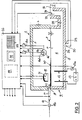
- FIG 2 is a simplified representation and using the same Reference numerals as shown in Figure 1, a glass melting plant, the Glass tub furnace 1 is loaded by a front insertion device 10 becomes.
- a quantity measuring device 11a for the quantity of the feed material is through indicated a box.
- Two exhaust channels 15, only one of which is visible is, are arranged mirror-symmetrically on both sides of the longitudinal axis of the tub.
- the amounts of oxidizing gas and fuel are detected by quantity measuring devices 16a and 16b, the associated ones Temperatures by temperature sensors 16c and 16d.
- the temperature sensors 29 and 30 serve to record the wall losses of the sub-furnace 4.
- the power of the pair of heating electrodes 12 is regulated by an actuator 13 or controlled.
- the current actual value is the by a current measuring device 13a Control arrangement 36 activated.
- the actual values of the individual controlled variables can also be obtained by the actuators what also applies to all other controlled variables.
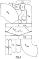
- FIG. 3 shows - not to scale - the individual heat balances or heat flows:
- Q GB is the heat flow from the upper furnace 2 through the melt level 8 to the lower furnace 4.
- Q B is the heat content of the fuel quantity
- Q A is the enthalpy of the combustion air preheated in the heat exchanger 14.
- Q WLKO is the sum of all wall, leak and cooling losses of the upper furnace 2, the wall losses due to the ambient air, the leak losses due to leaks in the furnace and the cooling losses due to burner cooling, for example.
- Q X are the exhaust gas losses escaping with the exhaust gases.
- the exhaust gases flow from the heat exchanger 14 into a material preheater 14a.
- the non-recoverable exhaust gas losses are labeled Q V.
- Q C is the enthalpy of the preheated charging material or the solid feed material, which is fed to the lower furnace 4 with this.
- Q el is the electrical heating power supplied to the sub-furnace 4 if there are heating electrodes.
- Q E is the endothermic heat of fusion and the energy for the decomposition of carbonates and the formation of silicates.
- Q WKB are the practically constant wall and cooling losses of the sub-furnace, whereby the cooling losses result from cooling the electrode holder.
- Q Glass is the enthalpy of the molten glass, which is transferred with the glass into connected units such as distribution and work tanks, feeders and glass processing machines.
Landscapes
- Chemical & Material Sciences (AREA)
- Engineering & Computer Science (AREA)
- Materials Engineering (AREA)
- Organic Chemistry (AREA)
- Chemical Kinetics & Catalysis (AREA)
- Electrochemistry (AREA)
- Glass Melting And Manufacturing (AREA)
- Waste-Gas Treatment And Other Accessory Devices For Furnaces (AREA)
- Manufacture, Treatment Of Glass Fibers (AREA)
- Vertical, Hearth, Or Arc Furnaces (AREA)
Claims (10)
- Procédé pour la régulation du chauffage dans des fours à cuve de fusion du verte (1) comprenant un four supérieur (2) et un four inférieur (4) dans lequel on forme une fonte de verre (7) avec une surface de fusion (8) à partir du matériau chargé (40), et cette fonte de verte est extraite hors du four inférieur, comprenant au moins un brûleur (16) associé au four supérieur (2), au moyen duquel on apporte une quantité d'énergie nécessaire pour la fusion, procédé dans lequel on détermine les températures et les quantités de carburant, d'air de combustion et du produit chargé, ainsi que les quantités calorifiques de la fonte de verte (7), caractérisé en ce que l'on calcule en permanence, à partir des données techniques concernant la fusion et à partir des données thermiques concernant la structure du four à cuve (1), un flux thermique à travers la surface de fusion (1), eta) on calcule tout d'abord en permanence un bilan thermique total pour la totalité du four (1) ;b) depuis les pertes par les parois, les pertes de refroidissement et les pertes par fuites, qui sont contenues dans le bilan thermique total et qui sont calculées, on soustrait les pertes par les parois et les pertes de refroidissement du four inférieur (4), spécifiques au four et pratiquement invariables ;c) à partir d'un bilan thermique du four supérieur (2) on détermine une valeur réelle pour le flux thermique qui est transféré à la fonte de verre (7) ;d) à partir d'un bilan thermique du four inférieur, on calcule une valeur de consigne pour le flux de chaleur qui est transféré à la fonte de verre (7), et qui est en permanence comparée avec la valeur réelle citée sous le point c) pour le flux thermique ; ete) la différence des deux valeurs est régulée sans retard par modification de l'apport d'énergie, jusqu'à la plus petite valeur possible.
- Procédé selon la revendication 1, caractérisé en ce que la régulation des écarts entre la valeur réelle et la valeur de consigne est exécutée au moins partiellement par régulation de la puissance d'au moins une paire d'électrodes de chauffage (12) qui se trouvent dans la fonte en fusion.
- Procédé selon la revendication 1, caractérisé en ce que la détermination du bilan thermique du four inférieur (4), est exécutée à partir de la capacité de fusion de verre, de la composition du mélange, des pertes thermiques par les parois du four inférieur (4) et de la température de consigne de la fonte de verre (7a) au niveau de la sortie (24) vers une cuve de travail ou vers un canal de répartition, après soustraction de l'énergie de chauffage électrique apportée à la fonte de verte, directement le cas échéant dans la fonte de verte, et de l'enthalpie du produit de fusion admis.
- Procédé selon la revendication 1, caractérisé en ce que la détermination du bilan thermique du four supérieur (2) est exécutée à partir de l'énergie de combustion apportée, de la chaleur des gaz d'échappement retournés via le préchauffeur pour le produit à charger et pour l'air de combustion, à partir des pertes par les parois, par les fuites et les pertes de refroidissement, et des pertes liées aux gaz d'échappement.
- Procédé selon la revendication 1, caractérisé en ce que la quantité de gaz d'échappement est calculée à partir de la quantité de carburant, de la quantité d'air de combustion, de la proportion d'oxygène dans les gaz brûlés, et à partir des gaz constituant le mélange.
- Procédé selon la revendication 1, caractérisé en ce que pour le calcul de l'enthalpie des gaz d'échappement, on utilise la quantité de gaz d'échappement, leurs températures, et la teneur calorifique spécifique des composants du gaz échappement.
- Procédé selon la revendication 1, caractérisé en ce que la régulation est exécutée par modification du rapport entre le carburant et l'air dans le four supérieur (2), égal à la valeur lambda.
- Procédé selon la revendication 7, caractérisé en ce que, dans la mesure d'assurer des conditions de fonctionnement réductrices, la teneur en oxygène des gaz d'échappement du four supérieur (2) est mesurée et régulée à une valeur minimale prédéterminée.
- Procédé selon la revendication 1, caractérisé en ce que, dans le but de minimiser les coûts de chauffage, le rapport entre l'admission de carburant et le chauffage électrique est choisi selon la valeur des coûts pour l'unité énergétique respective.
- Procédé selon la revendication 1, caractérisé en ce que la valeur de consigne du flux de chaleur depuis le four supérieur (2) jusqu'au four inférieur (4) est choisie à proportion de la capacité en masse de la fonte de verte (7) dans le four inférieur (4), de sorte qu'une capacité plus élevée est compensée grâce à une densité de flux thermique spécifique plus élevée, et inversement.
Applications Claiming Priority (2)
| Application Number | Priority Date | Filing Date | Title |
|---|---|---|---|
| DE19521513A DE19521513C2 (de) | 1995-06-13 | 1995-06-13 | Verfahren zur Regelung der Beheizung von Glas-Wannenöfen |
| DE19521513 | 1995-06-13 |
Publications (3)
| Publication Number | Publication Date |
|---|---|
| EP0748773A2 EP0748773A2 (fr) | 1996-12-18 |
| EP0748773A3 EP0748773A3 (fr) | 1997-01-15 |
| EP0748773B1 true EP0748773B1 (fr) | 1999-01-27 |
Family
ID=7764285
Family Applications (1)
| Application Number | Title | Priority Date | Filing Date |
|---|---|---|---|
| EP96108994A Expired - Lifetime EP0748773B1 (fr) | 1995-06-13 | 1996-06-05 | Procédé de régulation du chauffage d'un four à cuve de fusion de verre |
Country Status (3)
| Country | Link |
|---|---|
| EP (1) | EP0748773B1 (fr) |
| AT (1) | ATE176218T1 (fr) |
| DE (2) | DE19521513C2 (fr) |
Cited By (2)
| Publication number | Priority date | Publication date | Assignee | Title |
|---|---|---|---|---|
| DE102004042438A1 (de) * | 2004-08-31 | 2006-03-16 | Thüringer Behälterglas GmbH Schleusingen | Verfahren zu einer im Sinne des Energieverbrauchs optimalen Glaskonditionierung |
| WO2022180345A1 (fr) * | 2021-02-26 | 2022-09-01 | Saint-Gobain Isover | Régulation de four |
Families Citing this family (10)
| Publication number | Priority date | Publication date | Assignee | Title |
|---|---|---|---|---|
| FR2776761B1 (fr) * | 1998-03-26 | 2000-05-05 | Axel Leona Georges M Thienpont | Four thermique equipe de chauffage electrique complementaire |
| DE19818953C1 (de) * | 1998-04-28 | 1999-07-08 | Sorg Gmbh & Co Kg | Verfahren und Anordnung zum Schmelzen von Glas in U-Flammen und Querflammenwannenöfen unter Reduzierung der Gehalte an NO¶x¶ und CO in den Abgasen |
| FR2781786B1 (fr) * | 1998-07-29 | 2000-10-13 | Stein Heurtey | Dispositif de conduite des fours de fusion et/ou d'affinage de verre |
| ES2192423B1 (es) * | 2000-04-18 | 2005-02-16 | Avacon, S.A. | Horno de fusion de vidrio. |
| ATE354546T1 (de) * | 2000-12-14 | 2007-03-15 | Software & Tech Glas Gmbh | Verfahren zur messung und regelung qualitätsbestimmender parameter der rauhschmelze von glasschmelzwannen |
| EP1266868A1 (fr) * | 2001-06-11 | 2002-12-18 | Avacon, S.A. | Four de fusion du verre |
| RU2206524C1 (ru) * | 2001-10-24 | 2003-06-20 | Иванищев Вячеслав Васильевич | Способ управления стекловаренным процессом |
| DE102010044430A1 (de) * | 2010-09-04 | 2012-03-08 | G I W E P Gesellschaft für industrielle Wärme, Energie- und Prozeßtechnik m.b.H | Verfahren zur Überwachung von gasbeheizten Ofenanlagen |
| DE102010041157B4 (de) | 2010-09-21 | 2016-01-28 | Software & Technologie Glas Gmbh (Stg) | Verfahren zum geregelten Betrieb eines regenerativ beheizten Industrieofens, Steuereinrichtung und Industrieofen |
| CN110991090B (zh) * | 2019-12-26 | 2023-04-11 | 广东工业大学 | 一种马蹄焰玻璃窑炉数据预处理及热效率计算方法及系统 |
Family Cites Families (3)
| Publication number | Priority date | Publication date | Assignee | Title |
|---|---|---|---|---|
| US4028083A (en) * | 1974-08-19 | 1977-06-07 | Johns-Manville Corporation | Method and apparatus for controlling temperature within a furnace |
| US3954433A (en) * | 1974-08-22 | 1976-05-04 | Owens-Corning Fiberglas Corporation | Method of and apparatus for coordinating the application of heat to a melt from sources above and below the melt surface |
| US4405351A (en) * | 1981-06-29 | 1983-09-20 | Owens-Corning Fiberglas Corporation | Method for controlling a glass melting furnace |
-
1995
- 1995-06-13 DE DE19521513A patent/DE19521513C2/de not_active Expired - Fee Related
-
1996
- 1996-06-05 AT AT96108994T patent/ATE176218T1/de not_active IP Right Cessation
- 1996-06-05 EP EP96108994A patent/EP0748773B1/fr not_active Expired - Lifetime
- 1996-06-05 DE DE59601212T patent/DE59601212D1/de not_active Expired - Fee Related
Cited By (3)
| Publication number | Priority date | Publication date | Assignee | Title |
|---|---|---|---|---|
| DE102004042438A1 (de) * | 2004-08-31 | 2006-03-16 | Thüringer Behälterglas GmbH Schleusingen | Verfahren zu einer im Sinne des Energieverbrauchs optimalen Glaskonditionierung |
| WO2022180345A1 (fr) * | 2021-02-26 | 2022-09-01 | Saint-Gobain Isover | Régulation de four |
| FR3120233A1 (fr) * | 2021-02-26 | 2022-09-02 | Saint-Gobain Isover | Régulation de four |
Also Published As
| Publication number | Publication date |
|---|---|
| EP0748773A2 (fr) | 1996-12-18 |
| DE19521513A1 (de) | 1996-12-19 |
| DE59601212D1 (de) | 1999-03-11 |
| EP0748773A3 (fr) | 1997-01-15 |
| ATE176218T1 (de) | 1999-02-15 |
| DE19521513C2 (de) | 1998-04-09 |
Similar Documents
| Publication | Publication Date | Title |
|---|---|---|
| DE3718276C2 (fr) | ||
| DE69910702T2 (de) | Vorrichtung zum Regeln der Schmelzung und/oder Entgasung von Glasschmelzofen | |
| DE19521513C2 (de) | Verfahren zur Regelung der Beheizung von Glas-Wannenöfen | |
| EP0638525B1 (fr) | Procédé de fusion de verre dans un four à bassin et four à bassin pour appliquer ledit procédé | |
| DE2632195B2 (de) | Verfahren zur Regelung der Beheizung von Koksofenbatterien | |
| EP2160364B1 (fr) | Four de fusion du verre et procédé pour réaliser la fusion de verres | |
| DE2335810A1 (de) | Elektrischer ofen zur erhitzung eines fliessfaehigen materials, vorzugsweise glas | |
| EP2619151B1 (fr) | Procédé pour faire fonctionner, de manière régulée, un four industriel à chauffage à régénération, four industriel avec dispositif de commande | |
| EP0864543B1 (fr) | Procédé et four de fusion de verre pour la fabrication de verres à haute température de fusion et à composants vaporisables | |
| DD250922A5 (de) | Glasschmelzofen und verfahren zum betreiben desselben | |
| EP0237604B1 (fr) | Procédé économique en énergie pour la fusion de verre | |
| DE2935416C2 (de) | Verfahren zum gleichmäßigen Beheizen eines Glasstromes in einem Speiser und Einrichtung zur Durchführung dieses Verfahrens | |
| EP1458649B1 (fr) | Procede de mesure et de regulation de parametres de qualite relatifs a la charge brute de cuves de fusion du verre | |
| DE3605740A1 (de) | Verfahren zur heizungsregelung in einem waermeofen | |
| EP3686163A1 (fr) | Bassin pour la fusion du verre | |
| DE2604852A1 (de) | Verfahren und vorrichtung zur erhitzung eines in einer schmelzwanne befindlichen, in waerme erweichenden materials, insbesondere glas | |
| EP2976586A2 (fr) | Procédé pour faire fonctionner de manière régulée un four industriel chauffé de manière régénérative, unité de commande et four industriel | |
| DE19818953C1 (de) | Verfahren und Anordnung zum Schmelzen von Glas in U-Flammen und Querflammenwannenöfen unter Reduzierung der Gehalte an NO¶x¶ und CO in den Abgasen | |
| DE60003729T2 (de) | Verfahren und Vorrichtung zur Regelung des gasförmigen Brennstoffstromes | |
| DE60102715T2 (de) | Elektrischer glasschmelzofen mit schwenkbaren wandelementen | |
| DE3022091A1 (de) | Verfahren und vorrichtung zur herstellung von blaeschenfreiem erschmolzenen glas | |
| DE2151959A1 (de) | Regelanordnung fuer Schmelzwannen | |
| DE60203280T2 (de) | Verfahren zum verbessern der metallurgischen eigenschaften von im ofen behandelten produkten | |
| DE69904477T2 (de) | Schmelzofen mit scherbenvorheizung und hinter-first-schornstein mit unterstützungssystem | |
| DE102013018090A1 (de) | Verfahren zur Betriebsoptimierung einer regenerativen Glasschmelzwanne mit Gasbrennern zur Temperierung eines in der Glasschmelzwanne befindlichen Glasbades sowie zugehöriger Brenner |
Legal Events
| Date | Code | Title | Description |
|---|---|---|---|
| PUAI | Public reference made under article 153(3) epc to a published international application that has entered the european phase |
Free format text: ORIGINAL CODE: 0009012 |
|
| PUAL | Search report despatched |
Free format text: ORIGINAL CODE: 0009013 |
|
| AK | Designated contracting states |
Kind code of ref document: A2 Designated state(s): AT BE CH DE ES FR GB IT LI NL |
|
| AK | Designated contracting states |
Kind code of ref document: A3 Designated state(s): AT BE CH DE ES FR GB IT LI NL |
|
| 17P | Request for examination filed |
Effective date: 19970201 |
|
| 17Q | First examination report despatched |
Effective date: 19980407 |
|
| GRAG | Despatch of communication of intention to grant |
Free format text: ORIGINAL CODE: EPIDOS AGRA |
|
| GRAG | Despatch of communication of intention to grant |
Free format text: ORIGINAL CODE: EPIDOS AGRA |
|
| GRAH | Despatch of communication of intention to grant a patent |
Free format text: ORIGINAL CODE: EPIDOS IGRA |
|
| GRAH | Despatch of communication of intention to grant a patent |
Free format text: ORIGINAL CODE: EPIDOS IGRA |
|
| GRAA | (expected) grant |
Free format text: ORIGINAL CODE: 0009210 |
|
| AK | Designated contracting states |
Kind code of ref document: B1 Designated state(s): AT BE CH DE ES FR GB IT LI NL |
|
| PG25 | Lapsed in a contracting state [announced via postgrant information from national office to epo] |
Ref country code: NL Free format text: LAPSE BECAUSE OF FAILURE TO SUBMIT A TRANSLATION OF THE DESCRIPTION OR TO PAY THE FEE WITHIN THE PRESCRIBED TIME-LIMIT Effective date: 19990127 Ref country code: IT Free format text: LAPSE BECAUSE OF FAILURE TO SUBMIT A TRANSLATION OF THE DESCRIPTION OR TO PAY THE FEE WITHIN THE PRE;WARNING: LAPSES OF ITALIAN PATENTS WITH EFFECTIVE DATE BEFORE 2007 MAY HAVE OCCURRED AT ANY TIME BEFORE 2007. THE CORRECT EFFECTIVE DATE MAY BE DIFFERENT FROM THE ONE RECORDED.SCRIBED TIME-LIMIT Effective date: 19990127 Ref country code: ES Free format text: THE PATENT HAS BEEN ANNULLED BY A DECISION OF A NATIONAL AUTHORITY Effective date: 19990127 |
|
| REF | Corresponds to: |
Ref document number: 176218 Country of ref document: AT Date of ref document: 19990215 Kind code of ref document: T |
|
| REG | Reference to a national code |
Ref country code: CH Ref legal event code: NV Representative=s name: KEMENY AG PATENTANWALTBUERO Ref country code: CH Ref legal event code: EP |
|
| GBT | Gb: translation of ep patent filed (gb section 77(6)(a)/1977) |
Effective date: 19990204 |
|
| REF | Corresponds to: |
Ref document number: 59601212 Country of ref document: DE Date of ref document: 19990311 |
|
| ET | Fr: translation filed | ||
| NLV1 | Nl: lapsed or annulled due to failure to fulfill the requirements of art. 29p and 29m of the patents act | ||
| PLBE | No opposition filed within time limit |
Free format text: ORIGINAL CODE: 0009261 |
|
| STAA | Information on the status of an ep patent application or granted ep patent |
Free format text: STATUS: NO OPPOSITION FILED WITHIN TIME LIMIT |
|
| 26N | No opposition filed | ||
| REG | Reference to a national code |
Ref country code: GB Ref legal event code: IF02 |
|
| PGFP | Annual fee paid to national office [announced via postgrant information from national office to epo] |
Ref country code: CH Payment date: 20080625 Year of fee payment: 13 |
|
| PGFP | Annual fee paid to national office [announced via postgrant information from national office to epo] |
Ref country code: AT Payment date: 20080624 Year of fee payment: 13 |
|
| PGFP | Annual fee paid to national office [announced via postgrant information from national office to epo] |
Ref country code: BE Payment date: 20080627 Year of fee payment: 13 |
|
| PGFP | Annual fee paid to national office [announced via postgrant information from national office to epo] |
Ref country code: DE Payment date: 20080819 Year of fee payment: 13 |
|
| PGFP | Annual fee paid to national office [announced via postgrant information from national office to epo] |
Ref country code: FR Payment date: 20080402 Year of fee payment: 13 |
|
| PGFP | Annual fee paid to national office [announced via postgrant information from national office to epo] |
Ref country code: GB Payment date: 20080521 Year of fee payment: 13 |
|
| REG | Reference to a national code |
Ref country code: CH Ref legal event code: PCAR Free format text: KEMENY AG PATENTANWALTBUERO;EISENGASSE 17;6004 LUZERN (CH) |
|
| BERE | Be: lapsed |
Owner name: *BETEILIGUNGEN SORG G.M.B.H. & CO. K.G. Effective date: 20090630 |
|
| REG | Reference to a national code |
Ref country code: CH Ref legal event code: PL |
|
| GBPC | Gb: european patent ceased through non-payment of renewal fee |
Effective date: 20090605 |
|
| REG | Reference to a national code |
Ref country code: FR Ref legal event code: ST Effective date: 20100226 |
|
| PG25 | Lapsed in a contracting state [announced via postgrant information from national office to epo] |
Ref country code: LI Free format text: LAPSE BECAUSE OF NON-PAYMENT OF DUE FEES Effective date: 20090630 Ref country code: FR Free format text: LAPSE BECAUSE OF NON-PAYMENT OF DUE FEES Effective date: 20090630 Ref country code: CH Free format text: LAPSE BECAUSE OF NON-PAYMENT OF DUE FEES Effective date: 20090630 |
|
| PG25 | Lapsed in a contracting state [announced via postgrant information from national office to epo] |
Ref country code: GB Free format text: LAPSE BECAUSE OF NON-PAYMENT OF DUE FEES Effective date: 20090605 |
|
| PG25 | Lapsed in a contracting state [announced via postgrant information from national office to epo] |
Ref country code: DE Free format text: LAPSE BECAUSE OF NON-PAYMENT OF DUE FEES Effective date: 20100101 Ref country code: BE Free format text: LAPSE BECAUSE OF NON-PAYMENT OF DUE FEES Effective date: 20090630 Ref country code: AT Free format text: LAPSE BECAUSE OF NON-PAYMENT OF DUE FEES Effective date: 20090605 |