EP0748908A2 - Schliesszylinder - Google Patents
Schliesszylinder Download PDFInfo
- Publication number
- EP0748908A2 EP0748908A2 EP96107539A EP96107539A EP0748908A2 EP 0748908 A2 EP0748908 A2 EP 0748908A2 EP 96107539 A EP96107539 A EP 96107539A EP 96107539 A EP96107539 A EP 96107539A EP 0748908 A2 EP0748908 A2 EP 0748908A2
- Authority
- EP
- European Patent Office
- Prior art keywords
- cylinder
- lock
- connecting bridge
- housing
- bore
- Prior art date
- Legal status (The legal status is an assumption and is not a legal conclusion. Google has not performed a legal analysis and makes no representation as to the accuracy of the status listed.)
- Granted
Links
Images



Classifications
-
- E—FIXED CONSTRUCTIONS
- E05—LOCKS; KEYS; WINDOW OR DOOR FITTINGS; SAFES
- E05B—LOCKS; ACCESSORIES THEREFOR; HANDCUFFS
- E05B9/00—Lock casings or latch-mechanism casings ; Fastening locks or fasteners or parts thereof to the wing
- E05B9/04—Casings of cylinder locks
- E05B9/045—Modular casings for adjusting the length of cylinder locks
Definitions
- the invention relates to a lock cylinder, in particular a double lock cylinder, the cylinder comprising a rotatable core and a cylinder housing accommodating the cylinder core, the cylinder housing consisting of a circular cylinder part and a web part projecting radially therefrom.
- This lock cylinder has, in a known manner, a connecting bridge made of harder material on the web part in order to connect the lock cylinder to the second lock cylinder for producing a double lock cylinder, or to a mounting part for a half cylinder.
- the connecting bridge has the faceplate screw hole.
- Lock cylinders of the type mentioned are state of the art and reference is made, for example, to CH-PS 679.169 and EP 0 438 654 A2. With such double lock cylinders that can be assembled from individual parts, it is possible to adapt the lengths of the cylinders and the position of the faceplate screw bore to the respective door dimensions.
- the known constructions have the disadvantage that they are either complicated to manufacture and assemble, which increases the cost of manufacture and storage, or that the web connection between the cylinders is not stable enough to withstand simple burglary tools.
- the object of the present invention is to assemble locking cylinders in the manner of a modular system with the desired dimensions and also to be able to assemble them at the installation site.
- the construction should be suitable for pin tumbler locks, in which the housing pins are in the web part, as well as for locks, in which the Control and tumbler elements are in the circular cylinder part.
- FIG. 1 shows a longitudinal section through a housing of a double cylinder lock with the connecting bridge removed.
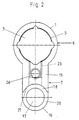
- 2 is a view of the inner end face of the cylinder housing according to arrow II in FIG. 1.
- 3 and 4 are mutually associated cracks of an extension piece for the cylinder housing and
- FIGS. 5 to 7 are mutually associated cracks of an extension piece for the cylinder core.
- 8 shows a partial section analogous to FIG. 1 through another embodiment and
- FIG. 9 shows sections of the longitudinal section through a cylinder lock in the area of the key tip.
- FIG. 1 shows in longitudinal section a locking cylinder according to the invention, which comprises two half cylinders with the cylinder housings 1 and 2.
- the core bore 3 sits the cylinder core, which is not shown in Fig.1.
- the cylinder housing 1 consists of the circular cylinder part 6 and the web part 7 projecting radially therefrom.
- the connecting bridge 8 is used to firmly connect the two cylinder housings 1 and 2. It comprises a cylinder bolt 9, which extends between the cylinder end faces 10. An axial retaining pin 11 extends from each of these cylinder end faces 10.
- the cylinder bolt 9 has the faceplate screw bore 13 perpendicular to the longitudinal axis 12, by means of which the finished double cylinder lock can be fixed in the door lock.
- the recess 14 serves for the free rotatability of the lock bit, not shown here, between the two half cylinders 1 and 2, which can be rotated by one of the two cylinder cores.
- FIG. 2 shows the top view of the inner end face 15 of the cylinder housing 1.
- the web part 7 ends at the bottom in a rounding 16.
- a receiving bore 17 is arranged centrally within this rounding 16, into which the retaining pin 11 of the connecting bridge 8 can be inserted.
- the web part 7 also has a detent recess 18, which is formed with the same radius as the radius of the cylinder bolt 9. This detent recess extends at least over a third of the length of the half cylinder from the inner end face 15 to the outside towards the outer end face 19 of the Cylinder housing.
- the stop surface 20 of the locking recess 18 serves as a stop for the cylinder end surface 10 of the connecting bridge.
- connection bridge 8 is fastened to the cylinder housings in such a way that the retaining pin 11 is inserted into the receiving bore 17 until the cylinder end surface 10 of the stop surface 20 strikes.
- the support surface 21 comes to lie on the cylinder surface of the cylinder bolt 9.
- a cylindrical bore 22 projects through the cylinder bolt 9 and is aligned with a threaded bore 23 of the cylinder housing.
- the connecting bridge 8 is screwed to the cylinder housing 1.
- the strength of this connection is the same or greater than if the double cylinder lock housing were in one piece.
- This connecting bridge is preferably made as a simple turned part, which is inexpensive to manufacture and can be easily stored in various lengths.
- the connecting bridge In its smallest dimension, the connecting bridge is so long that between the two inner end faces 15 of the cylinder housing 1, 2 the locking ring can be freely rotated with little play.
- the connecting bridge 8 When the connecting bridge 8 is lengthened, the lengthening is gradually increased in practice, one or more of the housing extension parts 24 being arranged, depending on the position of the faceplate screw bore on the cylinder housing 1 and / or 2, as shown in the drawings in FIGS.
- the outer dimension of the housing extension part 24 corresponds to the outer dimension of the cylinder housing and thus also has a circular cylinder part and a web part. The web part ends at the bottom in the support surface 21, which is designed analogously to the support surface of the cylinder housing.
- the housing extension part 24 By means of the stepped bore 25 and a corresponding screw, the housing extension part 24 is screwed onto the inner end face 15 of the cylinder housing 1 (or analogously to the cylinder housing 2 in FIG. 1). The screw is screwed into the screw hole 26.
- the core bore 27 has a diameter which corresponds approximately to the diameter of the cylinder core. In the expanded Abbritit 28, the diameter is selected so that the housing extension part can be pushed over the circlip, with which the cylinder core is axially secured in the usual way. See Fig. 8.
- the pins 30 engage in a corresponding diametrical recess in the cylinder core, so that a rotary connection is established.
- the engagement slot 31 has the same effect as the analog diametrical slot of the cylinder core and is used for the optional engagement or disengagement of a coupling element which lies in the locking ring.
- stepped step 32 which allows a plurality of such housing extension parts to be plugged onto one another by pushing the extended section 28 onto the stepped step 32.
- the fastening screw 33 (Fig. 8) must then of course be adapted to the added lengths of the stepped bores 25.
- FIG. 8 shows the left half cylinder 1 in view, while the housing extension part 24 is cut.
- the lock ring 34 is also shown in view.
- the core extension part 29 is only shown in dashed lines for the sake of better illustration.
- the circlip has the reference numeral 35 and is seated in an annular groove 36 of the cylinder core 37. It is shown in broken lines how the pin 30 of the core extension part 29 in the cylinder core 37 and 37, respectively. engage its slot.
- FIG. 1 If the arrangement according to the invention of the connecting bridge 8 is used in the case of pin tumbler locks, a construction as shown in FIG.
- the displaceable housing pin 38 is guided within a hollow fixing pin 39.
- the fixing pin 39 is screwed into a stepped bore 40 by means of the thread 41.
- the compression spring 42 is supported on a plug 43.
- the axial movement of the housing pin 38 in the direction of the key channel 44 is limited by the collar 45 and the stop 46.
- the core pin 47 is displaceable in the core bore 48 of the cylinder core and is held in the corresponding closed position by the control recess 49 of the key 50.
- the core pin bore 52 is immersed at the rotation and division plane 51, so that the core pin 47 cannot fall out of the core pin bore during assembly.
- This construction makes it easier to insert the housing pin when installing the lock.
Landscapes
- Mechanical Engineering (AREA)
- Engineering & Computer Science (AREA)
- Lock And Its Accessories (AREA)
- Fluid-Damping Devices (AREA)
- Chairs Characterized By Structure (AREA)
- Dowels (AREA)
- Pens And Brushes (AREA)
- Lubrication Of Internal Combustion Engines (AREA)
- Actuator (AREA)
- Underground Structures, Protecting, Testing And Restoring Foundations (AREA)
- Connection Of Plates (AREA)
- Hydrogenated Pyridines (AREA)
- Clamps And Clips (AREA)
- Catching Or Destruction (AREA)
Abstract
Description
- Die Erfindung betrifft einen Schließzylinder, insbesondere Doppelschließzylinder, wobei der Zylinder einen drehbetätigbaren Kern und ein den Zylinderkern aufnehmendes Zylindergehäuse umfaßt, wobei das Zylindergehäuse aus einem Kreiszylinderteil und einem davon radial vorspringenden Stegteil besteht. Dieser Schließzylinder weist in bekannter Weise am Stegteil eine Verbindungsbrücke aus härterem Werkstoff auf, um den Schließzylinder mit dem zweiten Schließzylinder zur Herstellung eines Doppelschließzylinders, oder mit einem Montageteil für einen Halbzylinder verbindet. Die Verbindungsbrücke weist die Stulpschraubenbohrung auf.
- Schließzylinder der genannten Art sind Stand der Technik und es wird beispielsweise auf die CH-PS 679.169 und die EP 0 438 654 A2 verwiesen. Mit solchen aus Einzelteilen zusammensetzbaren Doppelschließzylindern ist es möglich, die Längen der Zylinder und die Lage der Stulpschraubenbohrung den jeweiligen Türabmessungen anzupassen.
- Die bekannten Konstruktionen haben den Nachteil, daß sie entweder kompliziert in der Herstellung und Montage sind, was die Herstellung und Lagerhaltung verteuert oder daß die Stegverbindung zwischen den Zylindern nicht stabil genug ist, um auch einfachen Einbruchswerkzeugen standzuhalten.
- Aufgabe der vorliegenden Erfindung ist es, Schließzylinder nach Art eines Baukastens mit den gewünschten Abmessungen zusammenstellen und auch am Einbauort montieren zu können. Dabei sollen möglichst wenig verschiedene Teile Verwendung finden. Die Konstruktion soll sowohl für Stiftzuhaltungsschlösser passend sein, bei denen die Gehäusestifte im Stegteil liegen, als auch für Schlösser, bei denen die Steuer- und Zuhaltungselemente im Kreiszylinderteil liegen. Weiters besteht die Aufgabe, bei einfachster Montage eine genügend feste Stegverbindung herzustellen.
- Die gestellte Aufgaben werden durch die Merkmale gemäß den Patentansprüchen gelöst.
- Nachfolgend wird die Erfindung anhand eines Ausführungsbeispieles näher beschrieben.
- Fig.1 zeigt einen Längsschnitt durch ein Gehäuse eines Doppelzylinderschlosses mit herausgenommener Verbindungsbrücke. Fig.2 ist eine Ansicht auf die Innenstirnfläche des Zylindergehäuses gemäß Pfeil II in Fig.1. Die Fig.3 und 4 sind einander zugeordnete Risse eines Verlängerungsstückes für das Zylindergehäuse und die Fig. 5 bis 7 sind einander zugeordnete Risse eines Verlängerungsstückes für den Zylinderkern. Fig. 8 zeigt einen Teilschnitt analog Fig.1 durch eine andere Ausführungsform und Fig.9 zeigt abschnittsweise den Längsschnitt durch ein Zylinderschloß im Bereich der Schlüsselspitze.
- Fig.1 zeigt im Längsschnitt einen erfindungsgemäßen Schließzylinder, der zwei Halbzylinder mit den Zylindergehäusen 1 und 2 umfaßt. In der Kernbohrung 3 sitzt der Zylinderkern, der in Fig.1 nicht dargestellt ist. Zu sehen sind Ringnuten 4 und Ringstege 5, die zusammen mit Abtast- und Sperrelementen des Zylinderkerns die Verdrehung des Zylinderkern ermöglichen oder verhindern.
- Wie auch der Fig.2 zu entnehmen ist, besteht das Zylindergehäuse 1 aus dem Kreiszylinderteil 6 und dem davon radial abstehenden Stegteil 7.
- Zur festen Verbindung der beiden Zylindergehäuse 1 und 2 dient die Verbindungsbrücke 8. Sie umfaßt einen Zylinderbolzen 9, der sich zwischen den Zylinderendflächen 10 erstreckt. Von diesen Zylinderendflächen 10 erstreckt sich jeweils ein axialer Haltezapfen 11. Der Zylinderbolzen 9 weist senkrecht auf die Längsachse 12 die Stulpschraubenbohrung 13 auf, mittels derer das fertige Doppelzylinderschloß im Türschloß fixiert werden kann. Die Ausnehmung 14 dient der freien Verdrehbarkeit des hier nicht dargestellten Schließbartes zwischen den beiden Halbzylindern 1 und 2 der von jeweils einem der beiden Zylinderkerne verdreht werden kann.
- Fig.2 zeigt die Aufsicht auf die Innenstirnfläche 15 des Zylindergehäuses 1. Der Stegteil 7 endet unten in einer Abrundung 16. Zentrisch innerhalb dieser Abrundung 16 ist eine Aufnahmebohrung 17 angeordnet, in die der Haltezapfen 11 der Verbindungsbrücke 8 eingesetzt werden kann.
- Der Stegteil 7 weist weiters jeweils eine Rastausnehmung 18 auf, die mit dem gleichen Radius ausgebildet ist, wie der Radius des Zylinderbolzens 9. Diese Rastausnehmung erstreckt sich zumindest über ein Drittel der Länge des Halbzylinders von der Innenstirnseite 15 nach außen in Richtung zur Aussenstirnseite 19 des Zylindergehäuses.
- Die Anschlagfläche 20 der Rastausnehmung 18 dient als Anschlag für die Zylinderendfläche 10 der Verbindungsbrücke.
- Die Befestigung der Verbindungsbrücke 8 mit den Zylindergehäusen erfolgt derart, daß der Haltezapfen 11 in die Aufnahmebohrung 17 gesteckt wird, bis die Zylinderendfläche 10 der Anschlagfläche 20 anschlägt. Die Stützfläche 21 kommt auf der Zylinderfläche des Zylinderbolzens 9 zu liegen. Den Zylinderbolzen 9 durchragt eine radiale Bohrung 22, die mit einer Gewindebohrung 23 des Zylindergehäuses fluchtet.
- Mittels einer entsprechend ausgebildeten Senkkopfschraube (hier nicht dargestellt) wird die Verbindungsbrücke 8 mit dem Zylindergehäuse 1 fest verschraubt. Die Festigkeit dieser Verbindung ist bei entsprechender Materialwahl für die Verbindungsbrücke gleich groß oder größer, als wenn das Doppelzylinderschloßgehäuse einstückig wäre.
- Es ist leicht verständlich, daß die Gesamtlänge des Doppelzylinderschlosses dadurch verändert werden kann, daß der Zylinderbolzen 9 der Verbindungsbrücke 8 verschieden lang ausgebildet wird. Diese Verbindungsbrücke ist bevorzugt als einfacher Drehteil hergestellt, der billig in der Herstellung ist und in verschiedenen Längen leicht auf Lager gelegt werden kann.
- In seiner kleinsten Dimension ist die Verbindungsbrücke so lange, daß zwischen den beiden Innenstirnflächen 15 der Zylindergehäuse 1,2 der Schließbartring mit geringem Spiel frei verdrehbar ist. Bei Verlängerung der Verbindungsbrücke 8 wird in der Praxis stufenweise verlängert, wobei je nach Lage der Stulpschraubenbohrung am Zylindergehäuse 1 und/oder 2 eine oder mehrere der Gehäuseverlängerungsteile 24 angeordnet werden, wie sie in Fig.3 und 4 zeichnerisch dargestellt sind. Die äußere Abmessung des Gehäuseverlängerungsteiles 24 entspricht der äußeren Abmessung des Zylindergehäuses und weist somit ebenfalls einen Kreiszylinderteil und einen Stegteil auf. Nach unten endet der Stegteil in der Stützfläche 21, die analog der Stützfläche des Zylindergehäuses ausgebildet ist. Mittels der Stufenbohrung 25 und einer entsprechenden Schraube wird der Gehäuseverlängerungsteil 24 an der Innenstirnfläche 15 des Zylindergehäuses 1 angeschraubt (oder analog am Zylindergehäuse 2 in Fig.1). Die Schraube wird in die Schraubbohrung 26 eingeschraubt.
- Die Kernbohrung 27 hat einen Durchmesser, der etwa dem Durchmesser des Zylinderkerns entspricht. In dem erweiterten Abschntit 28 ist der Durchmesser so gewählt, daß der Gehäuseverlängerungsteil über den Seegerring geschoben werden kann, mit welchem der Zylinderkern in üblicher Weise axial gesichert ist. Siehe dazu Fig.8.
- Die Fig. 5 bis 7 zeigen in einander zugeordneten Rissen den Kernverlängerungsteil 29, der in die Kernbohrung 27 eingesetzt wird und die Verbindung zwischen Zylinderkern und Schließbartring herstellt, wie dies an sich bekannt ist. Die Zapfen 30 greifen in eine entsprechende diametrale Ausnehmung des Zylinderkerns ein, sodaß eine Drehverbindung hergestellt ist. Der Eingriffsschlitz 31 hat die gleiche Wirkung wie der analoge diametrale Schlitz des Zylinderkerns und dient der wahlweisen Einkupplung oder Auskupplung eines Kupplungselementes, das im Schließbartring liegt.
- Unter Bezugnahme auf Fig.3 wird noch auf die abgesetzte Stufe 32 hingewiesen, die es erlaubt, mehrere solcher Gehäuseverlängerungsteile aufeinander zu stecken, in dem der erweiterte Abschnitt 28 auf die abgesetzte Stufe 32 aufgeschoben wird.
- Die Befestigungsschraube 33 (Fig.8) muß dann selbstverständlich den addierten Längen der Stufenbohrungen 25 angepaßt sein.
- In Fig.8 ist der linke Halbzylinder 1 in Ansicht dargestellt, während der Gehäuseverlängerungsteil 24 geschnitten ist. Der Schließbartring 34 ist ebenfalls in Ansicht dargestellt. Der Kernverlängerungsteil 29 ist der besseren Darstellung halber nur strichliert eingezeichnet. Der Seegerring trägt das Bezugszeichen 35 und sitzt in einer Ringnut 36 des Zylinderkerns 37. Strichliert eingezeichnet ist zu sehen, wie die Zapfen 30 des Kernverlängerungsteiles 29 in den Zylinderkern 37 resp. dessen Schlitz eingreifen.
- Bei der Schloßkonstruktion gemäß den Fig. 1 bis 8 liegen die mit dem Schlüssel zusammenwirkenden Steuer-und Sperrelemente innerhalb des Zylinderkerns, die mit den Ringnuten und Ringstegen 4,5 zusammenwirken, die ebenfalls im Bereich um den Zylinderkern angeordnet sind. Somit spielen bei dieser Schloßkonstruktion die Platzverhältnisse im Stegteil 7 keine oder nur eine geringe Rolle.
- Wenn die erfindungsgemäße Anordnung der Verbindungsbrücke 8 bei Stiftzuhaltungsschlössern Anwendung findet, kann bei der innen liegenden Stiftzuhaltung oder bei mehreren weiter innen liegenden Stiftzuhaltungen eine Konstruktion zur Anwendung gelangen, wie sie in Fig.9 dargestellt ist. Der verschiebbare Gehäusestift 38 ist innerhalb eines hohlen Fixierstiftes 39 geführt. Der Fixierstift 39 ist in einer Stufenbohrung 40 mittels des Gewindes 41 eingeschraubt. Die Druckfeder 42 stützt sich an einem Pfropfen 43 ab. Die axiale Bewegung des Gehäusestiftes 38 in Richtung zum Schlüsselkanal 44 ist durch den Kragen 45 und den Anschlag 46 begrenzt.
- Der Kernstift 47 ist in der Kernbohrung 48 des Zylinderkerns verschiebbar und wird durch die Steuerausnehmung 49 des Schlüssels 50 in der entsprechenden Schließstellung gehalten. An der Dreh- und Teilungsebene 51 ist die Kernstiftbohrung 52 eingestaucht, sodaß der Kernstift 47 bei der Montage nicht aus der Kernstiftbohrung herausfallen kann.
- Diese Konstruktion erleichtert das Einsetzen des Gehäusestiftes bei der Schloßmontage.
Claims (6)
- Schließzylinder, der entweder zwei Halbzylinder (Doppelschließzylinder) oder einen Halbzylinder und einen Montageteil umfaßt, wobei die Halbzylinder aus einem Kreiszylinderteil und einem davon radial abstehenden Stegteil mit halbkreisförmiger Abrundung bestehen und die zwei Halbzylinder, oder ein Halbzylinder mit dem Befestigungsteil, über eine massive Verbindungsbrücke verbunden sind, dadurch gekennzeichnet, daß die Verbindungsbrücke (8) aus einem Zylinderbolzen gebildet ist, dessen Radius etwa gleich dem Radius der Abrundung (16) des Stegteiles (17) ist, und der Zylinderbolzen (9) an der dem/den Halbzylindern zugewandten Zylinderendflächen (10) einen axialen Haltezapfen (11) aufweist, daß die Verbindungsbrücke (8) in einer Rastausnehmung (18) des Stegteiles (7) angeordnet ist, wobei die Rastausnehmung mit einem Radius gebildet ist, der dem Radius des Zylinderbolzens (9) entspricht, daß sich die Rastausnehmung (18) zumindest über ein Drittel der Länge des Halbzylinders von der Innenstirnfläche (15) nach außen hin erstreckt und daß sich von der Rastausnehmung eine Aufnahmebohrung (17) für den Haltezapfen (11) erstreckt.
- Schließzylinder nach Anspruch 1, dadurch gekennzeichnet, daß zur Fixierung der Verbindungsbrücke (8)am Zylindergehäuse (1,2) der Zylinderbolzen (9) eine radiale Bohrung (22) aufweist, die mit einer Gewindebohrung (23) im Stegteil des Zylindergehäuses fluchtet und eine Schraube (53) aufnimmt.
- Schließzylinder nach Anspruch 1 oder 2, dadurch gekennzeichnet, daß die Verbindungsbrücke (8) mit den Haltezapfen (11) und dem Zylinderbolzen (9) ein Drehteil, bevorzugt aus Stahl, ist, wobei gegebenenfalls im Bereich der Stulpschraubenbohrung (13) eine Ausnehmung (14) für die freie Verdrehbarkeit des Schließbartes (54) vorgesehen ist.
- Schließzylinder nach einem der vorhergehenden Ansprüche, dadurch gekennzeichnet, daß zur Verlängerung des Zylindergehäuses ein oder mehrere Gehäuseverlängerungsteile (24) vorgesehen sind, die aus einem Ringteil mit der Kernbohrung (27) und dem Stegteil mit einer Stützfläche (21) zur Abstützung am Zylinderbolzen (9) bestehen, wobei die Kernbohrung (27) einen erweiterten Abschnitt (28) und der Ringteil außen eine abgesetzte Stufe (32) aufweisen.
- Schließzylinder nach Anspruch 4, dadurch gekennzeichnet, daß der/die Gehäuseverlängerungsteile (24) mittels einer Schraube (33) an der Innenstirnfläche (15) des/der Zylindergehäuse(s) (1,2) befestigt sind.
- Schließzylinder nach einem der Ansprüche 4 oder 5, dadurch gekennzeichnet, daß in der Kernbohrung (27) ein oder mehrere Kernverlängerungsteile (29) angeordnet sind, die mit dem Zylinderkern (37) oder miteinander auf Drehung gekuppelt sind.
Priority Applications (1)
| Application Number | Priority Date | Filing Date | Title |
|---|---|---|---|
| SI9630358T SI0748908T1 (en) | 1995-06-13 | 1996-05-11 | Locking cylinder |
Applications Claiming Priority (3)
| Application Number | Priority Date | Filing Date | Title |
|---|---|---|---|
| AT0100895A AT405960B (de) | 1995-06-13 | 1995-06-13 | Schliesszylinder |
| AT1008/95 | 1995-06-13 | ||
| AT100895 | 1995-06-13 |
Publications (3)
| Publication Number | Publication Date |
|---|---|
| EP0748908A2 true EP0748908A2 (de) | 1996-12-18 |
| EP0748908A3 EP0748908A3 (de) | 1997-11-19 |
| EP0748908B1 EP0748908B1 (de) | 2002-01-16 |
Family
ID=3504813
Family Applications (1)
| Application Number | Title | Priority Date | Filing Date |
|---|---|---|---|
| EP96107539A Expired - Lifetime EP0748908B1 (de) | 1995-06-13 | 1996-05-11 | Schliesszylinder |
Country Status (9)
| Country | Link |
|---|---|
| EP (1) | EP0748908B1 (de) |
| AT (2) | AT405960B (de) |
| CZ (1) | CZ282240B6 (de) |
| DE (2) | DE29512441U1 (de) |
| DK (1) | DK0748908T3 (de) |
| ES (1) | ES2168406T3 (de) |
| FR (1) | FR2735513B3 (de) |
| NL (1) | NL1000826C2 (de) |
| SI (1) | SI0748908T1 (de) |
Cited By (5)
| Publication number | Priority date | Publication date | Assignee | Title |
|---|---|---|---|---|
| DE29801490U1 (de) * | 1998-01-30 | 1999-06-02 | Bks Gmbh, 42549 Velbert | Verbinder für einen Profilzylinder |
| DE19831846A1 (de) * | 1998-07-16 | 2000-01-20 | Winkhaus Fa August | Schließzylinder |
| WO2002016712A3 (en) * | 2000-08-24 | 2002-08-29 | Dom Sicherheitstechnik | Cylinder lock |
| EP2826933A2 (de) | 2013-07-19 | 2015-01-21 | La Industrial Cerrajera S.A. | Schließzylinder mit einer Verbindungsbrücke |
| DE102014205960A1 (de) * | 2014-03-31 | 2015-10-01 | Bks Gmbh | Schließzylinder und Montagevorrichtung |
Families Citing this family (6)
| Publication number | Priority date | Publication date | Assignee | Title |
|---|---|---|---|---|
| DE29608645U1 (de) * | 1996-03-01 | 1996-08-01 | Keller, Ernst, Richterswil | Einbau-Doppelschliesszylinder für ein Sicherheitsschloss |
| DE102006001267B3 (de) * | 2006-01-10 | 2007-05-10 | Seccor High Security Gmbh | Verlängerbarer Zylinderkörper für elektronische Schließzylinder |
| AT504009B1 (de) | 2006-07-07 | 2008-06-15 | Michael Ing Makivic | Zylinderschloss |
| DE102007035265B4 (de) | 2007-07-27 | 2020-11-26 | ABUS Seccor GmbH | Verlängerbarer Zylinderkörper mit Führungselementen in der Zylinderkernbohrung |
| DE102010047429B4 (de) | 2010-10-04 | 2014-10-30 | ABUS Seccor GmbH | Verlängerbarer Zylinderkörper mit axialen Befestigungsbolzen |
| ES2592954B1 (es) * | 2015-06-01 | 2017-08-03 | Talleres De Escoriaza, S.A. (Tesa) | Cilindro de cerradura modular |
Family Cites Families (8)
| Publication number | Priority date | Publication date | Assignee | Title |
|---|---|---|---|---|
| GB1581095A (en) * | 1978-02-16 | 1980-12-10 | Lowe & Fletcher Ltd | Lock with two key-receiving members |
| EP0022233A1 (de) * | 1979-07-05 | 1981-01-14 | C.I.S.A. Costruzioni Italiane Serrature Affini S.p.A. | Schloss mit koaxialem Doppelzylinder |
| CH679169A5 (en) * | 1988-05-05 | 1991-12-31 | Ernst Keller | Morticed double cylinder for door lock - has flexible longitudinal component joining housing sections together |
| FR2655367B1 (fr) * | 1989-12-05 | 1992-04-03 | Vachette Sa | Serrure a barillet double a condamnation mecanique et electrique. |
| DE9000746U1 (de) * | 1990-01-24 | 1991-05-23 | BKS GmbH, 5620 Velbert | Profil-Doppelschließzylinder |
| DE4106709A1 (de) * | 1991-03-02 | 1992-09-03 | Dom Sicherheitstechnik | Aus mehreren einheiten zusammensetzbarer schliesszylinder |
| DE4213382A1 (de) * | 1992-01-17 | 1993-07-22 | Giesser Irmgard | Doppelsperrzylinder |
| US5501087A (en) * | 1993-05-27 | 1996-03-26 | Keller; Ernst | Rotary locking cylinder for a safety lock |
-
1995
- 1995-06-13 AT AT0100895A patent/AT405960B/de not_active IP Right Cessation
- 1995-07-17 NL NL1000826A patent/NL1000826C2/xx not_active IP Right Cessation
- 1995-07-21 FR FR9508896A patent/FR2735513B3/fr not_active Expired - Lifetime
- 1995-08-02 DE DE29512441U patent/DE29512441U1/de not_active Expired - Lifetime
-
1996
- 1996-05-11 AT AT96107539T patent/ATE212098T1/de not_active IP Right Cessation
- 1996-05-11 EP EP96107539A patent/EP0748908B1/de not_active Expired - Lifetime
- 1996-05-11 ES ES96107539T patent/ES2168406T3/es not_active Expired - Lifetime
- 1996-05-11 DE DE59608579T patent/DE59608579D1/de not_active Expired - Fee Related
- 1996-05-11 SI SI9630358T patent/SI0748908T1/xx unknown
- 1996-05-11 DK DK96107539T patent/DK0748908T3/da active
- 1996-06-04 CZ CZ961613A patent/CZ282240B6/cs not_active IP Right Cessation
Cited By (6)
| Publication number | Priority date | Publication date | Assignee | Title |
|---|---|---|---|---|
| DE29801490U1 (de) * | 1998-01-30 | 1999-06-02 | Bks Gmbh, 42549 Velbert | Verbinder für einen Profilzylinder |
| DE19831846A1 (de) * | 1998-07-16 | 2000-01-20 | Winkhaus Fa August | Schließzylinder |
| WO2002016712A3 (en) * | 2000-08-24 | 2002-08-29 | Dom Sicherheitstechnik | Cylinder lock |
| EP2826933A2 (de) | 2013-07-19 | 2015-01-21 | La Industrial Cerrajera S.A. | Schließzylinder mit einer Verbindungsbrücke |
| DE102014205960A1 (de) * | 2014-03-31 | 2015-10-01 | Bks Gmbh | Schließzylinder und Montagevorrichtung |
| EP2930289A1 (de) * | 2014-03-31 | 2015-10-14 | BKS GmbH | SCHLIEßZYLINDER UND MONTAGEVORRICHTUNG |
Also Published As
| Publication number | Publication date |
|---|---|
| CZ282240B6 (cs) | 1997-06-11 |
| FR2735513A3 (fr) | 1996-12-20 |
| ES2168406T3 (es) | 2002-06-16 |
| AT405960B (de) | 2000-01-25 |
| FR2735513B3 (fr) | 1997-05-30 |
| DK0748908T3 (da) | 2002-03-18 |
| NL1000826C2 (nl) | 1996-12-13 |
| ATE212098T1 (de) | 2002-02-15 |
| ATA100895A (de) | 1999-05-15 |
| SI0748908T1 (en) | 2002-06-30 |
| EP0748908B1 (de) | 2002-01-16 |
| DE59608579D1 (de) | 2002-02-21 |
| DE29512441U1 (de) | 1995-11-09 |
| CZ161396A3 (en) | 1997-01-15 |
| EP0748908A3 (de) | 1997-11-19 |
Similar Documents
| Publication | Publication Date | Title |
|---|---|---|
| DE102011102159B4 (de) | Modularer Schließzylinder | |
| EP4150178B1 (de) | Hangschloss-grundbausatz und hangschloss-system | |
| AT405960B (de) | Schliesszylinder | |
| EP2886754B1 (de) | Schliesszylinder mit magnetischem Zuhaltungsstift | |
| DE3828354C2 (de) | ||
| DE9000746U1 (de) | Profil-Doppelschließzylinder | |
| DE2113008A1 (de) | Zylinderschloss | |
| DD142222A5 (de) | Steuereinrichtung,insbesondere schloss | |
| CH706692A2 (de) | Schliesszylinder. | |
| DE20102793U1 (de) | Zylinder-Hebelschloß | |
| DE68903447T2 (de) | Sicherheitszylinder fuer ein schloss und entsprechender schluessel. | |
| DE3626551C2 (de) | ||
| DE3134471C2 (de) | ||
| DE69201668T2 (de) | Zylinderschloss. | |
| DE20218302U1 (de) | Zylinderbolzen-Führungsbuchse mit Bolzensicherung | |
| WO2016161530A1 (de) | Schlüssel, schlüsselrohling und zugehöriger schliesszylinder mit zusätzlichem sicherheitsmerkmal | |
| DE9400744U1 (de) | Schließzylinder | |
| DE19746580A1 (de) | Baukastensystem zur Zusammenstellung von Schließzylindern | |
| DE3733518A1 (de) | Schliesszylinder | |
| CH706693A2 (de) | Schliesszylinder. | |
| DE8706875U1 (de) | Kupplungseinrichtung an Doppel-Schließzylindern | |
| DE10107398C2 (de) | Bausatz für Möbelschlösser oder Möbeloliven mit einem Adaptergehäuse zur Aufnahme für unterschiedliche Schließsysteme | |
| EP0591661A2 (de) | Codierbares Zylinderschloss | |
| DE2930425A1 (de) | Zylinderschloss | |
| EP0296337B1 (de) | Profilschliesszylinder |
Legal Events
| Date | Code | Title | Description |
|---|---|---|---|
| PUAI | Public reference made under article 153(3) epc to a published international application that has entered the european phase |
Free format text: ORIGINAL CODE: 0009012 |
|
| AK | Designated contracting states |
Kind code of ref document: A2 Designated state(s): AT BE CH DE DK ES FR GB IT LI NL SE |
|
| AX | Request for extension of the european patent |
Free format text: SI PAYMENT 960511 |
|
| PUAL | Search report despatched |
Free format text: ORIGINAL CODE: 0009013 |
|
| AK | Designated contracting states |
Kind code of ref document: A3 Designated state(s): AT BE CH DE DK ES FR GB IT LI NL SE |
|
| AX | Request for extension of the european patent |
Free format text: SI PAYMENT 960511 |
|
| 17P | Request for examination filed |
Effective date: 19980121 |
|
| GRAG | Despatch of communication of intention to grant |
Free format text: ORIGINAL CODE: EPIDOS AGRA |
|
| 17Q | First examination report despatched |
Effective date: 20010312 |
|
| GRAG | Despatch of communication of intention to grant |
Free format text: ORIGINAL CODE: EPIDOS AGRA |
|
| GRAH | Despatch of communication of intention to grant a patent |
Free format text: ORIGINAL CODE: EPIDOS IGRA |
|
| GRAH | Despatch of communication of intention to grant a patent |
Free format text: ORIGINAL CODE: EPIDOS IGRA |
|
| GRAA | (expected) grant |
Free format text: ORIGINAL CODE: 0009210 |
|
| REG | Reference to a national code |
Ref country code: GB Ref legal event code: IF02 |
|
| AK | Designated contracting states |
Kind code of ref document: B1 Designated state(s): AT BE CH DE DK ES FR GB IT LI NL SE |
|
| AX | Request for extension of the european patent |
Free format text: SI PAYMENT 19960511 |
|
| REF | Corresponds to: |
Ref document number: 212098 Country of ref document: AT Date of ref document: 20020215 Kind code of ref document: T |
|
| REG | Reference to a national code |
Ref country code: CH Ref legal event code: EP |
|
| REG | Reference to a national code |
Ref country code: CH Ref legal event code: NV Representative=s name: A. BRAUN, BRAUN, HERITIER, ESCHMANN AG PATENTANWAE |
|
| REF | Corresponds to: |
Ref document number: 59608579 Country of ref document: DE Date of ref document: 20020221 |
|
| REG | Reference to a national code |
Ref country code: DK Ref legal event code: T3 |
|
| GBT | Gb: translation of ep patent filed (gb section 77(6)(a)/1977) |
Effective date: 20020406 |
|
| ET | Fr: translation filed | ||
| REG | Reference to a national code |
Ref country code: ES Ref legal event code: FG2A Ref document number: 2168406 Country of ref document: ES Kind code of ref document: T3 |
|
| PLBE | No opposition filed within time limit |
Free format text: ORIGINAL CODE: 0009261 |
|
| STAA | Information on the status of an ep patent application or granted ep patent |
Free format text: STATUS: NO OPPOSITION FILED WITHIN TIME LIMIT |
|
| 26N | No opposition filed | ||
| REG | Reference to a national code |
Ref country code: SI Ref legal event code: IF |
|
| REG | Reference to a national code |
Ref country code: CH Ref legal event code: PFA Owner name: EVVA - WERK SPEZIALERZEUGUNG VON ZYLINDER-UND SIC Free format text: EVVA - WERK SPEZIALERZEUGUNG VON ZYLINDER-UND SICHERHEITSSCHLOESSERN GESELLSCHAFT M.B.H. & CO. KOMMANDITGESELLSCHAFT#WIENERBERGSTRASSE 59-65#A-1120 WIEN (AT) -TRANSFER TO- EVVA - WERK SPEZIALERZEUGUNG VON ZYLINDER-UND SICHERHEITSSCHLOESSERN GESELLSCHAFT M.B.H. & CO. KOMMANDITGESELLSCHAFT#WIENERBERGSTRASSE 59-65#A-1120 WIEN (AT) |
|
| PGFP | Annual fee paid to national office [announced via postgrant information from national office to epo] |
Ref country code: NL Payment date: 20090529 Year of fee payment: 14 Ref country code: ES Payment date: 20090408 Year of fee payment: 14 Ref country code: DK Payment date: 20090514 Year of fee payment: 14 |
|
| PGFP | Annual fee paid to national office [announced via postgrant information from national office to epo] |
Ref country code: SE Payment date: 20090525 Year of fee payment: 14 Ref country code: IT Payment date: 20090529 Year of fee payment: 14 Ref country code: DE Payment date: 20090519 Year of fee payment: 14 Ref country code: AT Payment date: 20090427 Year of fee payment: 14 |
|
| PGFP | Annual fee paid to national office [announced via postgrant information from national office to epo] |
Ref country code: BE Payment date: 20090506 Year of fee payment: 14 |
|
| PGFP | Annual fee paid to national office [announced via postgrant information from national office to epo] |
Ref country code: CH Payment date: 20090526 Year of fee payment: 14 |
|
| PGFP | Annual fee paid to national office [announced via postgrant information from national office to epo] |
Ref country code: GB Payment date: 20090409 Year of fee payment: 14 |
|
| PGFP | Annual fee paid to national office [announced via postgrant information from national office to epo] |
Ref country code: FR Payment date: 20091106 Year of fee payment: 14 |
|
| BERE | Be: lapsed |
Owner name: *EVVA - WERK SPEZIALERZEUGUNG VON ZYLINDER-UND SIC Effective date: 20100531 |
|
| REG | Reference to a national code |
Ref country code: NL Ref legal event code: V1 Effective date: 20101201 |
|
| REG | Reference to a national code |
Ref country code: CH Ref legal event code: PL |
|
| REG | Reference to a national code |
Ref country code: DK Ref legal event code: EBP |
|
| GBPC | Gb: european patent ceased through non-payment of renewal fee |
Effective date: 20100511 |
|
| PG25 | Lapsed in a contracting state [announced via postgrant information from national office to epo] |
Ref country code: AT Free format text: LAPSE BECAUSE OF NON-PAYMENT OF DUE FEES Effective date: 20100511 |
|
| EUG | Se: european patent has lapsed | ||
| REG | Reference to a national code |
Ref country code: FR Ref legal event code: ST Effective date: 20110131 |
|
| PG25 | Lapsed in a contracting state [announced via postgrant information from national office to epo] |
Ref country code: LI Free format text: LAPSE BECAUSE OF NON-PAYMENT OF DUE FEES Effective date: 20100531 Ref country code: CH Free format text: LAPSE BECAUSE OF NON-PAYMENT OF DUE FEES Effective date: 20100531 |
|
| REG | Reference to a national code |
Ref country code: SI Ref legal event code: KO00 Effective date: 20110107 |
|
| PG25 | Lapsed in a contracting state [announced via postgrant information from national office to epo] |
Ref country code: IT Free format text: LAPSE BECAUSE OF NON-PAYMENT OF DUE FEES Effective date: 20100511 Ref country code: SE Free format text: LAPSE BECAUSE OF NON-PAYMENT OF DUE FEES Effective date: 20100512 Ref country code: BE Free format text: LAPSE BECAUSE OF NON-PAYMENT OF DUE FEES Effective date: 20100531 Ref country code: NL Free format text: LAPSE BECAUSE OF NON-PAYMENT OF DUE FEES Effective date: 20101201 |
|
| PG25 | Lapsed in a contracting state [announced via postgrant information from national office to epo] |
Ref country code: DK Free format text: LAPSE BECAUSE OF NON-PAYMENT OF DUE FEES Effective date: 20100531 Ref country code: DE Free format text: LAPSE BECAUSE OF NON-PAYMENT OF DUE FEES Effective date: 20101201 |
|
| PG25 | Lapsed in a contracting state [announced via postgrant information from national office to epo] |
Ref country code: FR Free format text: LAPSE BECAUSE OF NON-PAYMENT OF DUE FEES Effective date: 20100531 |
|
| REG | Reference to a national code |
Ref country code: ES Ref legal event code: FD2A Effective date: 20110715 |
|
| PG25 | Lapsed in a contracting state [announced via postgrant information from national office to epo] |
Ref country code: GB Free format text: LAPSE BECAUSE OF NON-PAYMENT OF DUE FEES Effective date: 20100511 Ref country code: ES Free format text: LAPSE BECAUSE OF NON-PAYMENT OF DUE FEES Effective date: 20110705 |
|
| PG25 | Lapsed in a contracting state [announced via postgrant information from national office to epo] |
Ref country code: ES Free format text: LAPSE BECAUSE OF NON-PAYMENT OF DUE FEES Effective date: 20100512 |