EP0748977A2 - Moyen obturateur pour conduites et appareillage de mise en place - Google Patents
Moyen obturateur pour conduites et appareillage de mise en place Download PDFInfo
- Publication number
- EP0748977A2 EP0748977A2 EP96101711A EP96101711A EP0748977A2 EP 0748977 A2 EP0748977 A2 EP 0748977A2 EP 96101711 A EP96101711 A EP 96101711A EP 96101711 A EP96101711 A EP 96101711A EP 0748977 A2 EP0748977 A2 EP 0748977A2
- Authority
- EP
- European Patent Office
- Prior art keywords
- bladder
- shut
- lock
- coupling member
- hose
- Prior art date
- Legal status (The legal status is an assumption and is not a legal conclusion. Google has not performed a legal analysis and makes no representation as to the accuracy of the status listed.)
- Withdrawn
Links
- 239000013013 elastic material Substances 0.000 claims abstract description 6
- 239000000463 material Substances 0.000 claims abstract description 5
- 238000007493 shaping process Methods 0.000 claims abstract description 5
- 239000007787 solid Substances 0.000 claims abstract description 4
- 230000008878 coupling Effects 0.000 claims description 38
- 238000010168 coupling process Methods 0.000 claims description 38
- 238000005859 coupling reaction Methods 0.000 claims description 38
- 238000010079 rubber tapping Methods 0.000 claims description 37
- 238000007789 sealing Methods 0.000 claims description 22
- 239000004744 fabric Substances 0.000 claims description 7
- 230000002787 reinforcement Effects 0.000 claims description 7
- 239000004519 grease Substances 0.000 claims description 6
- 210000002445 nipple Anatomy 0.000 claims description 4
- 239000007789 gas Substances 0.000 description 8
- 238000005553 drilling Methods 0.000 description 6
- 208000002352 blister Diseases 0.000 description 4
- 238000004804 winding Methods 0.000 description 4
- 238000003780 insertion Methods 0.000 description 3
- 230000037431 insertion Effects 0.000 description 3
- 230000007704 transition Effects 0.000 description 3
- 241000251468 Actinopterygii Species 0.000 description 2
- IJGRMHOSHXDMSA-UHFFFAOYSA-N Atomic nitrogen Chemical compound N#N IJGRMHOSHXDMSA-UHFFFAOYSA-N 0.000 description 2
- 230000000903 blocking effect Effects 0.000 description 2
- 238000013461 design Methods 0.000 description 2
- 230000000694 effects Effects 0.000 description 2
- 239000011261 inert gas Substances 0.000 description 2
- 230000008439 repair process Effects 0.000 description 2
- 238000013022 venting Methods 0.000 description 2
- 229910000831 Steel Inorganic materials 0.000 description 1
- 208000027418 Wounds and injury Diseases 0.000 description 1
- 238000013459 approach Methods 0.000 description 1
- 238000010276 construction Methods 0.000 description 1
- 230000000881 depressing effect Effects 0.000 description 1
- 230000003670 easy-to-clean Effects 0.000 description 1
- 238000000034 method Methods 0.000 description 1
- 238000000465 moulding Methods 0.000 description 1
- 229910052757 nitrogen Inorganic materials 0.000 description 1
- 239000004033 plastic Substances 0.000 description 1
- 230000008569 process Effects 0.000 description 1
- 230000009467 reduction Effects 0.000 description 1
- 239000011343 solid material Substances 0.000 description 1
- 230000003068 static effect Effects 0.000 description 1
- 239000010959 steel Substances 0.000 description 1
- 238000012549 training Methods 0.000 description 1
- 238000011144 upstream manufacturing Methods 0.000 description 1
- 230000000007 visual effect Effects 0.000 description 1
Images


Classifications
-
- F—MECHANICAL ENGINEERING; LIGHTING; HEATING; WEAPONS; BLASTING
- F16—ENGINEERING ELEMENTS AND UNITS; GENERAL MEASURES FOR PRODUCING AND MAINTAINING EFFECTIVE FUNCTIONING OF MACHINES OR INSTALLATIONS; THERMAL INSULATION IN GENERAL
- F16L—PIPES; JOINTS OR FITTINGS FOR PIPES; SUPPORTS FOR PIPES, CABLES OR PROTECTIVE TUBING; MEANS FOR THERMAL INSULATION IN GENERAL
- F16L55/00—Devices or appurtenances for use in, or in connection with, pipes or pipe systems
- F16L55/10—Means for stopping flow in pipes or hoses
- F16L55/12—Means for stopping flow in pipes or hoses by introducing into the pipe a member expandable in situ
- F16L55/128—Means for stopping flow in pipes or hoses by introducing into the pipe a member expandable in situ introduced axially into the pipe or hose
- F16L55/132—Means for stopping flow in pipes or hoses by introducing into the pipe a member expandable in situ introduced axially into the pipe or hose the closure device being a plug fixed by radially deforming the packing
- F16L55/134—Means for stopping flow in pipes or hoses by introducing into the pipe a member expandable in situ introduced axially into the pipe or hose the closure device being a plug fixed by radially deforming the packing by means of an inflatable packing
Definitions
- the invention relates to a shut-off device for pipelines, in particular for transporting gaseous media, with a bladder which can be expanded by a pressure medium and which is connected at least at one end to a hose, within which pressure lines or the like run.
- a device for setting the shut-off device in a pipe consisting of a coupling member which can be connected to a tapping bridge attached to the pipe and a tubular sluice which can be connected to the coupling member, the coupling member being provided with a shut-off valve and the sluice having a shut-off connection to the surroundings having.
- Blocking systems must be used that can be used to block lines without gas outflow.
- blocking systems include, for example, bladder setting devices or plug setting devices.
- a bladder setting device in which a cylindrical tube is provided inside, in which two bladders connected in series are arranged. These bubbles usually consist of thin-walled rubber and are composed of several individual parts vulcanized together. By combining several parts, there is a risk that the shut-off bladder will expand mainly in the longitudinal direction of the pipe when it is exposed to compressed air and finally burst before the filling pressure is reached. For this reason, the bladder - like a soccer ball - is surrounded by a shell made of a solid fabric, which gives the bladder its strength and shape when expanded.
- the firm fabric of the cover has hardly any elastic properties.
- the bladder cannot adapt to every pipe cross-section.
- an envelope with a bladder must be used which has an internal diameter.
- the surface of the shell is also structured. As a result of the structuring, the sheath cannot completely cover the inner wall of the pipeline to be shut off. Creep gas can consequently escape between the fabric and the inner wall of the pipeline, so that the known shut-off device forms a clear weak point here.
- shut-off devices are also known in which only one bladder is used. For safety reasons, however, in many cases only shut-off devices are used in which two bubbles arranged one behind the other and connected but which can be acted on separately are used. The pipeline space between the two bubbles can then be vented.
- a setting device with a lock which can be screwed onto a tapping sleeve placed around the pipeline.
- An axially displaceable tube is provided in the interior of the lock, which receives the shut-off device in its interior.
- the tube of the lock is pushed to the bottom of the previously drilled and shut-off pipeline, and then the bubbles therein are pushed out through holes provided in the lower region of the tube, which were previously rotated in the corresponding direction within the pipeline.
- the inner tube of the setting device is necessary in order to give the bubbles the direction to be specified so that they are not guided in the direction opposite to the shut-off point to be provided. A visual control from the outside of the course of the bubbles is naturally not possible.
- the pipeline to be shut off must first be drilled using a tapping device.
- the tapping device is first screwed onto a threaded coupling connected to a tapping bridge.
- the tapping bridge or the threaded coupling is provided with a ball valve so that the tapping point can be shut off after the pipe has been tapped and the tapping device can be unscrewed from the tapping bridge or the threaded coupling.
- the lock is screwed onto the tapping bridge, the ball valve is opened again and the shut-off device (bubbles) can be set as described above.
- a disadvantage of this system is that both the tapping device and the setting sluice have to be screwed onto the tapping bridge.
- screwing it on is very time consuming, Especially in cold winter months, this process is associated with high physical exertion for the personnel entrusted with the work.
- shut-off device is to be further developed so that the disadvantages shown are avoided.
- the device for setting the shut-off device is to be modified so that its use is considerably simplified and its safety is increased.
- the bladder is constructed in several parts and consists at least of an inner bladder which holds the pressure medium, an intermediate sheath surrounding the inner bladder and an outer bladder surrounding the intermediate sheath, the inner bladder and outer bladder being made of a rubber-elastic material and the intermediate sheath being made of a solid , shaping material are made.
- This multi-part construction of the bladder creates an extremely inexpensive shut-off device which has a high sealing effect. While the inner bladder is being expanded, the intermediate shell of the inner bladder forces a shape which is passed on to the rubber-elastic outer bladder until the outer bladder is sealed on the inner tube circumference. Since the outer shell also consists of a rubber-elastic material, it nestles completely against the inside diameter of the pipe and also compensates for unevenness.
- shut-off device can continue to be used even if the outer bladder should tear when it is set.
- the intermediate shell can take over the function of the outer bladder for a short time.
- the multiple parts offer a quick and inexpensive replacement for damaged ones Individual parts. A torn outer shell, for example, can easily be replaced before the shut-off device is used the next time.
- the intermediate sheath consists of an air-permeable fabric, which is particularly advantageously a corset.
- This material offers sufficient shaping strength and is still so flexible that it can take on sealing functions in an emergency.
- This intermediate casing prevents the inner bladder from expanding in an uncontrolled manner and is comparable to the outer casing of a football, for example.
- the hose has an intermediate, at least two-part, openable chamber, in which plug connectors can be accommodated for uncoupling the pressure lines from the bladder.
- plug connectors can be formed by mother / father connectors assigned to each pressure line.
- the chamber can preferably be formed by a screw connection consisting of two sleeves.
- the bladder In order to securely connect the bladder to the hose, it is provided at least at one of its ends in a transition area with a cross-sectional reduction on a tubular extension.
- the connection between bladder and hose can be connected by winding and knotting, in the manner in which fish hooks are attached to the fishing line.
- the hose preferably has a wire reinforcement running in the circumferential direction.
- the reinforcement can be wound spirally. This training ensures that the bladder (s) can be securely attached to the hose.
- the hose due to its length, the hose must be rolled up to and transported from the work area. The reinforcement forces the rolled-up hose onto a shape that lasts for a relatively long time, and thus a completely unwound hose will not run straight but in an arc.
- This arcuate course determines the direction in which the bladder (s) is (are) inserted when the shut-off device is set, that is to say when the bladder (s) are inserted into the pipeline.
- the setting device can be significantly simplified because the operators can determine the direction in which the bladder is set by appropriately guiding the hose without further auxiliary devices.
- a ball is connected to the plug closing the front end of the hose via an arcuate arm which is adapted to the hose curvature.
- the ball swings quickly and easily in the right direction of the pipeline.
- the device for setting the shut-off device in a pipeline is characterized in that the tubular lock can be inserted into the coupling member as far as it will go and can be connected by means of a thread-less tension lock.
- the tension lock consists of two diametrically arranged on the coupling member, which can be brought into the inner region of the coupling member with their clamping jaws, which engage in an outer circular groove of circular cross section, the locking elements with respect to the clamping jaws are mounted eccentrically so that the lock is pulled against a sealing ring lying on an axial shoulder in the coupling member during the delivery and the gas-tight connection is established.
- the tension lock designed in this way is relatively unaffected by dirt and easy to clean if necessary.
- the sealing ring is preferably made of rubber.
- the lock is equipped with an additional lockable connection, it can be flushed with inert gas.
- the sluice is provided in its upper region with a plurality of axially spaced sealing rings, the inner diameter of which is adapted to the outer diameter of the hose.
- the lock in the area of the sealing rings is provided with a grease nipple, through which grease can be injected if necessary, on the one hand to effect the seal and on the other hand to maintain the elasticity of the sealing rings.
- the entire system for tapping a gas-carrying pipeline and setting a shut-off device consisting of a coupling member that can be connected to a tapping bridge attached to the pipeline, a tapping device and a tubular sluice is simplified if both the tapping device and the sluice can be inserted into the coupling member as far as possible and can be connected to it by means of a thread-less tension lock. This makes it possible to remove the tapping device after drilling the pipeline and fitting the sluice to insert the shut-off device or the bubbles in a short time.
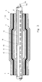
- FIG. 1 shows a shut-off device consisting of two bubbles 1 and 2 spaced apart along an axis 3.
- the bubbles 1 and 2 have a cylindrical jacket shape, the cylinder axis coinciding with the axis 3.
- transition regions 4 to tubular projections 5 with a smaller diameter are provided.
- the shut-off device is introduced with the bladder 2 ahead into a pipeline to be shut off, for example a gas line.
- the bubbles 1, 2 are constructed in several parts. Between the inner bladder 62 drawn on the tube 8 ′′ and the outer bladder 60 which takes over the actual sealing, an intermediate sheath 61 is arranged, which is made of a solid material which gives the inner bladder 62 the shape.
- This material is preferably air-permeable and a fabric from which corselets are usually made.
- the inner bladder and the outer bladder are made of a rubber-elastic material, a plastic or rubber. The shaping takes place exclusively through the intermediate shell 61, which prevents the inner bladder 62 from expanding in the longitudinal direction.
- the rear bladder 1 in the direction of insertion is closed in the area of the lugs 5 by plugs 6.
- the front bladder 2 is provided with a stopper 6 in the neck 5 facing the bladder 1.
- the other end of the bladder 2 is closed by a molded part 7.
- Both bubbles 1, 2 are connected by a flexible, but largely tensile and pressure-resistant hose 8 so that they can be inserted into the pipeline to be shut off.
- the tube 8 connects the opposite ends of the bladders 1 and 2 and is led out of the rear end of the bladder 1 in the insertion direction and is connected to a head part 40 via a screw connection 39 provided at its end.
- the part 8 'of the hose 8 lying between the bubbles 1 and 2 also has two openings 9a and 9b which are spaced apart from one another.
- the hose 8 can run through the bubbles 1, 2 continuously or each end in their tubular extensions 5, so that a separate hose is provided between the bubbles 1 and 2.
- the pressure line 10a is used to apply a pressure medium, preferably compressed air, to the bladder 1 and ends in the bladder 1.
- the pressure lines 10b to 10e are passed through the bladder 1.
- the pressure lines 10b and 10c lead to the two openings 9a and 9b.
- the pressure line 10d serves to pressurize the bladder 2 and ends in the bladder 2.
- the pressure line 10e is passed through the bladder 2 and adjoins the molded part 7.
- the pressure line 10e is used to detect the internal pipe pressure existing in front of the bladder introduced into the pipe. For this purpose, the pressure line 10e is connected via the head part 40 to a manometer (not shown here).
- the hose 8 ' opens into the tubular extension 5 of the bladder 2, as a result of which the hose 8' and the tubular extension 5 overlap approximately over the entire length of the extension 5.
- the outer diameter of the hose 8 corresponds approximately to the inner diameter of the extension 5.
- the plug 6 has a number of bores corresponding to the number of incoming pressure lines, into which the pressure lines are glued in a sealing manner. In the exemplary embodiment according to FIG. 1, it is only the pressure lines 10d and 10e.
- the bubbles 1, 2 are connected to the tube by means of binding, that is to say winding of a band, via the tubular projections 5.
- the binding or tying of the bubbles 1, 2 takes place in the manner in which fish hooks are also connected to the fishing line. For this purpose, several turns of a band are wrapped around the tubular extension and then the end of the band is pulled under the windings and lashed down. However, it is also possible to fix the tubular extension 5 of the bubbles 1 and 2 via a clamp 11. An airtight hollow body is created by appropriately closing the ends.
- the bladder 2 is closed with a molded part 7 having a shaft 12 in an analogous manner to how the plug 6 is inserted into the tubular extension 5 at the other end of the bladder 2.
- the pressure line 10e is glued into the inner region of an axial bore 13 through the shaft 12 of the molded part 7.
- the bore 13 opens out through an opening 14.
- the hose 8 ', 8' ' can be provided with a reinforcement 16 (steel wire) running in a spiral in the circumferential direction.
- a suitable selection of the reinforcement 16 gives the hose 8 such stability that the tubular extensions 5 of the bubbles 1 and 2 can be connected to the hose without a plug 6 in the hose 8, as shown in FIGS. 1 and 2 should be introduced.
- the hose 8 can consequently be guided in one piece through both bladders 1, 2 and its front end ends with the front end of the bladder 2.
- an opening 9c is provided in a hose 8 ′, 8 ′′, at which the pressure line 10 ends in order to be able to fill the bladder 1, 2 with compressed air.
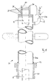
- a plug 17 is introduced at its front end, which has a central bore 19. This bore 19 is connected to the pressure line 10e.
- a ball 15 is connected to the stopper 17 via a bent arm 18.
- the arm 18 is hollow and connects to the bore 19.
- the pressure line 10e is connected to the environment via an opening 18e provided in the arm 18, so that it can pass on the pressure present in the pipeline.
- the ball 15 is used to guide the bubbles 1, 2 in the correct direction when they are introduced into the pipeline when they hit the inner wall of the pipeline in a manner not shown here.
- a chamber 73 Upstream of the bubbles 1 and / or 2 is a chamber 73 formed by two sleeves 70, 71, which are screwed together.
- the pressure lines 10, 10a, 10b, ... are releasably accommodated via plug connectors 74, so that the pressure lines 10, 10a, 10b, ... behind the bubbles 1, 2 can be separated from the setting tool or other control devices.
- the sleeves 70, 71 are connected to the respective hose ends 8, for example by means of a clamp 80 or winding.
- a bayonet lock can also be used.
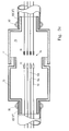
- FIG. 4 shows the tapping device 25 with the coupling member 21, which can be screwed via the external thread 36 provided on it to a tapping bridge, not shown here, which is connected to the pipeline.
- the coupling member 21 is tubular and has an upper region 29 with a larger diameter, which serves as a receiving part for the correspondingly designed counterpart for the coupling member 21.
- the clamping jaws 31, 31 a of the clamping elements 32, 32 a protrude into the interior of the coupling member 21.
- the clamping jaws 31, 31a form an eccentric due to the corresponding articulation of the clamping elements 32, 32a.
- the tapping device 25 has at its lower end the counterpart 24 designed for the coupling member 21.
- This counterpart 24 is sleeve-shaped and a tubular section 26 is soldered in its upper region.
- the outer circumference of the counterpart 24 is provided with a circumferential annular groove 23 with a circular arc cross section.
- the tapping device 25 is inserted with the counterpart 24 into the coupling member until its end 27 strikes the O-ring 35.
- the eccentric clamping jaws 31, 31 a slide into the annular groove 23 and pull the counterpart 24 and thus the drilling device 25 into the coupling member 21 in a gas-tight manner.
- the pipeline not shown here, can then be drilled through the drill pipe 28.
- tapping bridges The design of the tapping bridges is well known, so that it is here no detailed explanation is required.
- the tapping bridge is provided with a ball valve, via which the tapped pipe can be closed, so that no gas can escape through the tapping bridge when the tapping device 25 is removed from the coupling member 21.
- the tapping device 25 is sealed gas-tight even in its upper region.
- the drill pipe 28 is sealed off from the tapping device 25 via O-rings 28 '. Gas which has accumulated within the tapping device can be flared off via the connecting piece 22 'provided with a ball valve 22a before the tapping device 25 is separated from the coupling member 21.
- FIG. 5 shows the sluice gate 20 for the shut-off device.
- the sluice gate 20 is also provided with a counterpart 24 to the coupling member 21.
- an annular shoulder is provided, into which a tube 20a is inserted and soldered.
- the upper region 20 'of the tube 20a is closed by a stopper 50 which has a bore 51 which is concentric with the tube 20a and into which a plurality of ring grooves are screwed and a plurality of sealing rings 37 are received axially spaced therein.
- the hose 8 running inside the lock 20 is indicated by a dash-dotted line.
- the sealing rings 37 are used for gas-tight sealing of the hose 8 in the lock 20.
- the hose 8 is drawn into the lock 20 from below (in the drawing) into the lock 20 before the screw connection 39 (FIG. 3 b) is fastened to it, via which the hose is then connected to the head piece 40.
- the lock 20 with the counterpart 24 is inserted into the coupling member 21 up to the stop and, as previously described, connected to the latter in a gas-tight manner via the tensioning elements 32, 32a.
- the ball valve of the tapping bridge not shown here, is opened, and the hose 8 is advanced, whereby the bubbles 1, 2 are pushed into the interior of the pipeline.
- the bubbles 1 and 2 in the pipeline completely are introduced, they are successively inflated via the pressure hoses 10a and 10d. As a result, they expand in the radial direction up to a multiple of their original diameter and come to rest on the inner wall of the pipeline.
- the strength of the elastic material and the wall thickness of the bubbles interact with their cylindrical jacket shape so that an uncontrolled expansion in the longitudinal direction of the tube is prevented.
- an overpressure is created in the area of part 8 'in the pipeline section between the two bubbles 1 and 2. This excess pressure can be reduced by venting through the two openings 9a, 9b and the associated pressure lines 10b, 10c.
- the pipeline section can also be flushed with an inert gas, for example nitrogen, via this venting device.
- the pressure present in the blocked pipeline can be measured via the molded part 7 or the plug 17 at the end of the bladder 2 and the pressure line 10e connected to it.
- the line 10e is connected via the head piece 40 to a manometer (not shown in more detail).
- the other pressure connections, which are connected by the head piece 40 are also not shown here.
- the opening 14 directed towards the tube wall prevents the opening from becoming clogged with dirt (see FIG. 2).
- connection connection 22 is also provided with a ball valve 22a.
- the stopper 50 is in the area between the sealing rings 37 with a Grease nipple 38 through which grease can be squeezed inside.
Landscapes
- Engineering & Computer Science (AREA)
- General Engineering & Computer Science (AREA)
- Mechanical Engineering (AREA)
- Pipe Accessories (AREA)
Applications Claiming Priority (2)
| Application Number | Priority Date | Filing Date | Title |
|---|---|---|---|
| DE19521834 | 1995-06-16 | ||
| DE19521834A DE19521834C2 (de) | 1994-08-01 | 1995-06-16 | Absperrvorrichtung für Rohrleitungen und Vorrichtung zum Setzen der Absperrvorrichtung |
Publications (2)
| Publication Number | Publication Date |
|---|---|
| EP0748977A2 true EP0748977A2 (fr) | 1996-12-18 |
| EP0748977A3 EP0748977A3 (fr) | 1997-01-08 |
Family
ID=7764472
Family Applications (1)
| Application Number | Title | Priority Date | Filing Date |
|---|---|---|---|
| EP96101711A Withdrawn EP0748977A3 (fr) | 1995-06-16 | 1996-02-07 | Moyen obturateur pour conduites et appareillage de mise en place |
Country Status (1)
| Country | Link |
|---|---|
| EP (1) | EP0748977A3 (fr) |
Cited By (5)
| Publication number | Priority date | Publication date | Assignee | Title |
|---|---|---|---|---|
| WO2000047928A1 (fr) * | 1999-02-11 | 2000-08-17 | Glynwed Pipe Systems Limited | Appareil permettant d'arreter l'ecoulement dans un tuyau |
| CN109882674A (zh) * | 2019-03-28 | 2019-06-14 | 浙江海洋大学 | 一种水管连接件 |
| CN111288180A (zh) * | 2020-03-26 | 2020-06-16 | 安徽省格致绿色建筑设计有限公司 | 一种膨胀止回器及带有膨胀止回器的流体输配控制结构 |
| EP3693648A4 (fr) * | 2017-10-02 | 2021-05-05 | Aleksandr Georgievich Chuiko | Dispositif d'isolation monobloc interne de connexion par soudure de conduit |
| CN113579309A (zh) * | 2021-09-07 | 2021-11-02 | 北京市自来水集团禹通市政工程有限公司 | 一种带压管道钻孔装置 |
Family Cites Families (11)
| Publication number | Priority date | Publication date | Assignee | Title |
|---|---|---|---|---|
| US3618639A (en) * | 1969-11-24 | 1971-11-09 | Cues Inc | Packer for sealing pipe leaks |
| US4013097A (en) * | 1974-06-28 | 1977-03-22 | Anthony Louis Calandra | Apparatus and method for damming a pipeline |
| US4155373A (en) * | 1976-12-06 | 1979-05-22 | Digiovanni Bernard A | Method for shutting off gas flow in plastic pipes |
| DE2713993C2 (de) * | 1977-03-30 | 1982-12-16 | Herbert 3257 Springe Lux | Einrichtung zum Öffnen, Absperren und Verschließen von gasdurchströmten Rohrleitungen |
| FR2429957A1 (fr) * | 1978-06-28 | 1980-01-25 | Kleber Colombes | Dispositif de raccordement de tuyaux ou applications similaires |
| DE3145284A1 (de) * | 1981-11-14 | 1983-05-19 | IBS Nagel GmbH & Co Spezialarmaturen, 5630 Remscheid | Vorrichtung zum absperren von gasleitungen |
| FR2589980B1 (fr) * | 1985-11-08 | 1988-04-29 | Leviel Christian | Dispositif dilatable d'obturation de canalisation |
| DE3719395A1 (de) * | 1987-06-11 | 1988-12-22 | Waf Gmbh Absperrgeraete Und Ap | Vorrichtung zum absperren von rohrleitungen |
| EP0529671B1 (fr) * | 1991-08-30 | 1995-08-02 | WILHELM KNEITZ & CO. AG | Matériau textile en couches, notamment pour des applications techniques |
| AUPM307693A0 (en) * | 1993-12-21 | 1994-01-20 | Uponor N.V. | Expandable plug |
| DE9412355U1 (de) * | 1994-08-01 | 1994-09-29 | K. Ullrich GmbH & Co KG, 67346 Speyer | Absperrvorrichtung für Rohrleitungen zum Transport von flüssigen oder gasförmigen Medien |
-
1996
- 1996-02-07 EP EP96101711A patent/EP0748977A3/fr not_active Withdrawn
Cited By (7)
| Publication number | Priority date | Publication date | Assignee | Title |
|---|---|---|---|---|
| WO2000047928A1 (fr) * | 1999-02-11 | 2000-08-17 | Glynwed Pipe Systems Limited | Appareil permettant d'arreter l'ecoulement dans un tuyau |
| EP3693648A4 (fr) * | 2017-10-02 | 2021-05-05 | Aleksandr Georgievich Chuiko | Dispositif d'isolation monobloc interne de connexion par soudure de conduit |
| US11644128B2 (en) | 2017-10-02 | 2023-05-09 | Aleksandr Georgievich CHUIKO | Device for the internal monolithic insulation of a welded pipeline joint |
| CN109882674A (zh) * | 2019-03-28 | 2019-06-14 | 浙江海洋大学 | 一种水管连接件 |
| CN109882674B (zh) * | 2019-03-28 | 2024-02-23 | 浙江海洋大学 | 一种水管连接件 |
| CN111288180A (zh) * | 2020-03-26 | 2020-06-16 | 安徽省格致绿色建筑设计有限公司 | 一种膨胀止回器及带有膨胀止回器的流体输配控制结构 |
| CN113579309A (zh) * | 2021-09-07 | 2021-11-02 | 北京市自来水集团禹通市政工程有限公司 | 一种带压管道钻孔装置 |
Also Published As
| Publication number | Publication date |
|---|---|
| EP0748977A3 (fr) | 1997-01-08 |
Similar Documents
| Publication | Publication Date | Title |
|---|---|---|
| DE2711408A1 (de) | Druckendverschraubung fuer nichtmetallische, flexible rohrleitungen | |
| DE19713989A1 (de) | Fitting für ein Kunststoffrohr | |
| DE60204287T2 (de) | Kupplung zur verbindung eines rohrs oder schlauchs durch einschieben | |
| DE3743170C1 (en) | Pipe screw-connection | |
| DE1425487A1 (de) | Drucksammler fuer Druckfluessigkeiten | |
| EP0367721B1 (fr) | Récipient obturable, surtout récipient sous pression | |
| EP0754899B1 (fr) | Soupape sphérique avec raccord rapide | |
| DE19521834C2 (de) | Absperrvorrichtung für Rohrleitungen und Vorrichtung zum Setzen der Absperrvorrichtung | |
| EP0748977A2 (fr) | Moyen obturateur pour conduites et appareillage de mise en place | |
| EP3011220A1 (fr) | Raccord de tuyaux | |
| DE2650371C3 (de) | Kupplungsmuffe aus Kunststoff für eine zugfeste Rohrverbindung | |
| DE7626310U1 (de) | Rohrelement mit hydraulischer enddichtung mittels beweglichem differentialkoerper | |
| DE3536297A1 (de) | Schlauch und kupplung umfassende anordnung sowie schlauchkupplung hierfuer | |
| DE1995298U (de) | Muffenverbindungen fuer rohrleitungen. | |
| DE1970807U (de) | Schlauchfassung. | |
| DE4211959A1 (de) | Rohrverbindung | |
| DE3724372A1 (de) | Rohrdichtkissen mit durchfuehrung | |
| EP0611912A1 (fr) | Méthode de réalisation d'une connextion entre un tuyau principal et un tuyau de branchement et appareil pour sa mise en oeuvre | |
| DE851290C (de) | Schlauchverbindung | |
| DE2611175A1 (de) | Chlauchbefestigungsvorrichtung | |
| EP4001724B1 (fr) | Dispositif de raccordement pour composants guidant des milieux | |
| EP0392148B1 (fr) | Raccord de tuyaux | |
| DE816042C (de) | Rohrverbindung, insbesondere fuer elastische Rohre und Schlaeuche | |
| DE2650392C3 (de) | KabelverschluOhülse | |
| DE840490C (de) | Armatur fuer Schlaeuche u. dgl. |
Legal Events
| Date | Code | Title | Description |
|---|---|---|---|
| PUAI | Public reference made under article 153(3) epc to a published international application that has entered the european phase |
Free format text: ORIGINAL CODE: 0009012 |
|
| PUAL | Search report despatched |
Free format text: ORIGINAL CODE: 0009013 |
|
| AK | Designated contracting states |
Kind code of ref document: A2 Designated state(s): AT BE DE FR NL |
|
| AK | Designated contracting states |
Kind code of ref document: A3 Designated state(s): AT BE DE FR NL |
|
| 17P | Request for examination filed |
Effective date: 19961219 |
|
| 17Q | First examination report despatched |
Effective date: 19990113 |
|
| STAA | Information on the status of an ep patent application or granted ep patent |
Free format text: STATUS: THE APPLICATION IS DEEMED TO BE WITHDRAWN |
|
| 18D | Application deemed to be withdrawn |
Effective date: 19991130 |