EP0748984B1 - Verfahren und Vorrichtung zur Vernichtung von Reaktionsgas durchVerbrennung - Google Patents
Verfahren und Vorrichtung zur Vernichtung von Reaktionsgas durchVerbrennung Download PDFInfo
- Publication number
- EP0748984B1 EP0748984B1 EP96420202A EP96420202A EP0748984B1 EP 0748984 B1 EP0748984 B1 EP 0748984B1 EP 96420202 A EP96420202 A EP 96420202A EP 96420202 A EP96420202 A EP 96420202A EP 0748984 B1 EP0748984 B1 EP 0748984B1
- Authority
- EP
- European Patent Office
- Prior art keywords
- combustion
- combustion unit
- expansion reservoir
- electro
- photographic
- Prior art date
- Legal status (The legal status is an assumption and is not a legal conclusion. Google has not performed a legal analysis and makes no representation as to the accuracy of the status listed.)
- Expired - Lifetime
Links
- 239000007789 gas Substances 0.000 title claims description 30
- 238000006243 chemical reaction Methods 0.000 title claims description 17
- 238000000034 method Methods 0.000 title claims description 12
- 238000002485 combustion reaction Methods 0.000 claims description 42
- QVGXLLKOCUKJST-UHFFFAOYSA-N atomic oxygen Chemical compound [O] QVGXLLKOCUKJST-UHFFFAOYSA-N 0.000 claims description 18
- 239000001301 oxygen Substances 0.000 claims description 18
- 229910052760 oxygen Inorganic materials 0.000 claims description 18
- 239000001257 hydrogen Substances 0.000 claims description 17
- 229910052739 hydrogen Inorganic materials 0.000 claims description 17
- UFHFLCQGNIYNRP-UHFFFAOYSA-N Hydrogen Chemical compound [H][H] UFHFLCQGNIYNRP-UHFFFAOYSA-N 0.000 claims description 16
- BASFCYQUMIYNBI-UHFFFAOYSA-N platinum Chemical compound [Pt] BASFCYQUMIYNBI-UHFFFAOYSA-N 0.000 claims description 16
- 239000012855 volatile organic compound Substances 0.000 claims description 16
- 238000006056 electrooxidation reaction Methods 0.000 claims description 15
- 239000008246 gaseous mixture Substances 0.000 claims description 15
- 239000000203 mixture Substances 0.000 claims description 11
- 230000006378 damage Effects 0.000 claims description 9
- 229910052697 platinum Inorganic materials 0.000 claims description 8
- XLYOFNOQVPJJNP-UHFFFAOYSA-N water Substances O XLYOFNOQVPJJNP-UHFFFAOYSA-N 0.000 claims description 3
- 230000000694 effects Effects 0.000 claims description 2
- 230000000977 initiatory effect Effects 0.000 claims description 2
- 238000011144 upstream manufacturing Methods 0.000 claims description 2
- 238000005868 electrolysis reaction Methods 0.000 description 14
- 239000000243 solution Substances 0.000 description 10
- 239000000446 fuel Substances 0.000 description 8
- 239000003054 catalyst Substances 0.000 description 7
- 239000000126 substance Substances 0.000 description 7
- 239000003792 electrolyte Substances 0.000 description 5
- IJGRMHOSHXDMSA-UHFFFAOYSA-N Atomic nitrogen Chemical compound N#N IJGRMHOSHXDMSA-UHFFFAOYSA-N 0.000 description 4
- 238000001816 cooling Methods 0.000 description 4
- MWUXSHHQAYIFBG-UHFFFAOYSA-N Nitric oxide Chemical compound O=[N] MWUXSHHQAYIFBG-UHFFFAOYSA-N 0.000 description 3
- 230000003197 catalytic effect Effects 0.000 description 3
- 229910052751 metal Inorganic materials 0.000 description 3
- 239000002184 metal Substances 0.000 description 3
- 239000002351 wastewater Substances 0.000 description 3
- OKTJSMMVPCPJKN-UHFFFAOYSA-N Carbon Chemical compound [C] OKTJSMMVPCPJKN-UHFFFAOYSA-N 0.000 description 2
- CURLTUGMZLYLDI-UHFFFAOYSA-N Carbon dioxide Chemical compound O=C=O CURLTUGMZLYLDI-UHFFFAOYSA-N 0.000 description 2
- 206010016754 Flashback Diseases 0.000 description 2
- ATUOYWHBWRKTHZ-UHFFFAOYSA-N Propane Chemical compound CCC ATUOYWHBWRKTHZ-UHFFFAOYSA-N 0.000 description 2
- PMZURENOXWZQFD-UHFFFAOYSA-L Sodium Sulfate Chemical compound [Na+].[Na+].[O-]S([O-])(=O)=O PMZURENOXWZQFD-UHFFFAOYSA-L 0.000 description 2
- QAOWNCQODCNURD-UHFFFAOYSA-N Sulfuric acid Chemical compound OS(O)(=O)=O QAOWNCQODCNURD-UHFFFAOYSA-N 0.000 description 2
- RAHZWNYVWXNFOC-UHFFFAOYSA-N Sulphur dioxide Chemical compound O=S=O RAHZWNYVWXNFOC-UHFFFAOYSA-N 0.000 description 2
- RTAQQCXQSZGOHL-UHFFFAOYSA-N Titanium Chemical compound [Ti] RTAQQCXQSZGOHL-UHFFFAOYSA-N 0.000 description 2
- 239000002253 acid Substances 0.000 description 2
- 150000001875 compounds Chemical class 0.000 description 2
- 238000004880 explosion Methods 0.000 description 2
- VNWKTOKETHGBQD-UHFFFAOYSA-N methane Chemical compound C VNWKTOKETHGBQD-UHFFFAOYSA-N 0.000 description 2
- 229910052757 nitrogen Inorganic materials 0.000 description 2
- 150000002896 organic halogen compounds Chemical class 0.000 description 2
- 238000007254 oxidation reaction Methods 0.000 description 2
- 230000002572 peristaltic effect Effects 0.000 description 2
- 239000001117 sulphuric acid Substances 0.000 description 2
- 235000011149 sulphuric acid Nutrition 0.000 description 2
- 239000010936 titanium Substances 0.000 description 2
- 229910001200 Ferrotitanium Inorganic materials 0.000 description 1
- GRYLNZFGIOXLOG-UHFFFAOYSA-N Nitric acid Chemical compound O[N+]([O-])=O GRYLNZFGIOXLOG-UHFFFAOYSA-N 0.000 description 1
- -1 VOXs Substances 0.000 description 1
- 208000027418 Wounds and injury Diseases 0.000 description 1
- 230000002159 abnormal effect Effects 0.000 description 1
- 230000002378 acidificating effect Effects 0.000 description 1
- 150000007513 acids Chemical class 0.000 description 1
- 239000003463 adsorbent Substances 0.000 description 1
- 239000002518 antifoaming agent Substances 0.000 description 1
- 230000015572 biosynthetic process Effects 0.000 description 1
- 230000009172 bursting Effects 0.000 description 1
- 239000001273 butane Substances 0.000 description 1
- 239000006227 byproduct Substances 0.000 description 1
- 239000001569 carbon dioxide Substances 0.000 description 1
- 229910002092 carbon dioxide Inorganic materials 0.000 description 1
- UBAZGMLMVVQSCD-UHFFFAOYSA-N carbon dioxide;molecular oxygen Chemical compound O=O.O=C=O UBAZGMLMVVQSCD-UHFFFAOYSA-N 0.000 description 1
- 238000006555 catalytic reaction Methods 0.000 description 1
- 239000003153 chemical reaction reagent Substances 0.000 description 1
- 239000003086 colorant Substances 0.000 description 1
- 239000000110 cooling liquid Substances 0.000 description 1
- 238000010790 dilution Methods 0.000 description 1
- 239000012895 dilution Substances 0.000 description 1
- 238000007599 discharging Methods 0.000 description 1
- 239000002360 explosive Substances 0.000 description 1
- 239000006260 foam Substances 0.000 description 1
- 150000002431 hydrogen Chemical class 0.000 description 1
- 230000007062 hydrolysis Effects 0.000 description 1
- 238000006460 hydrolysis reaction Methods 0.000 description 1
- 238000011065 in-situ storage Methods 0.000 description 1
- 208000014674 injury Diseases 0.000 description 1
- 238000009434 installation Methods 0.000 description 1
- IJDNQMDRQITEOD-UHFFFAOYSA-N n-butane Chemical compound CCCC IJDNQMDRQITEOD-UHFFFAOYSA-N 0.000 description 1
- OFBQJSOFQDEBGM-UHFFFAOYSA-N n-pentane Natural products CCCCC OFBQJSOFQDEBGM-UHFFFAOYSA-N 0.000 description 1
- 239000003345 natural gas Substances 0.000 description 1
- 230000003472 neutralizing effect Effects 0.000 description 1
- 229910000510 noble metal Inorganic materials 0.000 description 1
- 238000011017 operating method Methods 0.000 description 1
- 230000003647 oxidation Effects 0.000 description 1
- 238000001139 pH measurement Methods 0.000 description 1
- 239000002574 poison Substances 0.000 description 1
- 231100000614 poison Toxicity 0.000 description 1
- 231100000572 poisoning Toxicity 0.000 description 1
- 230000000607 poisoning effect Effects 0.000 description 1
- 239000001294 propane Substances 0.000 description 1
- 230000005855 radiation Effects 0.000 description 1
- 239000012495 reaction gas Substances 0.000 description 1
- 239000002683 reaction inhibitor Substances 0.000 description 1
- 230000029219 regulation of pH Effects 0.000 description 1
- 230000001105 regulatory effect Effects 0.000 description 1
- 229910052938 sodium sulfate Inorganic materials 0.000 description 1
- 235000011152 sodium sulphate Nutrition 0.000 description 1
- 238000001179 sorption measurement Methods 0.000 description 1
- 229910001220 stainless steel Inorganic materials 0.000 description 1
- 239000010935 stainless steel Substances 0.000 description 1
- 239000004291 sulphur dioxide Substances 0.000 description 1
- 235000010269 sulphur dioxide Nutrition 0.000 description 1
- 239000013589 supplement Substances 0.000 description 1
- 229910052719 titanium Inorganic materials 0.000 description 1
- 239000002341 toxic gas Substances 0.000 description 1
Images
Classifications
-
- F—MECHANICAL ENGINEERING; LIGHTING; HEATING; WEAPONS; BLASTING
- F23—COMBUSTION APPARATUS; COMBUSTION PROCESSES
- F23C—METHODS OR APPARATUS FOR COMBUSTION USING FLUID FUEL OR SOLID FUEL SUSPENDED IN A CARRIER GAS OR AIR
- F23C13/00—Apparatus in which combustion takes place in the presence of catalytic material
-
- F—MECHANICAL ENGINEERING; LIGHTING; HEATING; WEAPONS; BLASTING
- F23—COMBUSTION APPARATUS; COMBUSTION PROCESSES
- F23G—CREMATION FURNACES; CONSUMING WASTE PRODUCTS BY COMBUSTION
- F23G7/00—Incinerators or other apparatus for consuming industrial waste, e.g. chemicals
- F23G7/06—Incinerators or other apparatus for consuming industrial waste, e.g. chemicals of waste gases or noxious gases, e.g. exhaust gases
- F23G7/061—Incinerators or other apparatus for consuming industrial waste, e.g. chemicals of waste gases or noxious gases, e.g. exhaust gases with supplementary heating
- F23G7/065—Incinerators or other apparatus for consuming industrial waste, e.g. chemicals of waste gases or noxious gases, e.g. exhaust gases with supplementary heating using gaseous or liquid fuel
-
- F—MECHANICAL ENGINEERING; LIGHTING; HEATING; WEAPONS; BLASTING
- F23—COMBUSTION APPARATUS; COMBUSTION PROCESSES
- F23C—METHODS OR APPARATUS FOR COMBUSTION USING FLUID FUEL OR SOLID FUEL SUSPENDED IN A CARRIER GAS OR AIR
- F23C2900/00—Special features of, or arrangements for combustion apparatus using fluid fuels or solid fuels suspended in air; Combustion processes therefor
- F23C2900/9901—Combustion process using hydrogen, hydrogen peroxide water or brown gas as fuel
Definitions
- the present invention concerns a method and a device for the destruction of a photographic solution.
- COD chemical oxygen demand
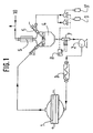
- FIG. 1 illustrates a device such as the one used in the treatment by electrolysis described in the patent application referred to above.
- the solution of developers which forms the electrolyte circulates in a closed loop in the installation.
- the electrolyte initially present in its totality in the expansion tank (4) is sent into the cooling coil (3) by means of the peristaltic pump (2). It then passes into the electrolysis cell (1), to emerge and be found in part in the expansion tank (4).
- the electrolysis cell is a closed, non-compartmentalized cell, preferably compact, comprising one or more platinum anodes and one or more titanium or stainless-steel cathodes, separated by an insulating joint.
- the anodes are SHOWA anodes consisting of titanium covered in pure platinum, which are in the form of metal plates or expanded-metal plates if the electrolyte circulation is parallel to the electrodes, and in the form of one expanded-metal plate if the electrolyte circulation is perpendicular to the electrodes.
- the expansion tank is provided with a calibrated orifice which enables a pressure close to atmospheric pressure to be maintained.
- This tank serves to cushion variations in the volume of the solution and to reduce the pressure of the gases produced during treatment (hydrogen, oxygen, carbon dioxide, volatile organic compounds (VOCs) and volatile halogenated organic compounds (VOXs)) to a pressure close to atmospheric pressure, and is used for the continuous addition of reagents.
- a device (5) enables the temperature in the expansion tank and coil (3) to be measured and regulated.
- a pH regulation loop is composed of a pH measurement device (7) inserted between the electrolysis cell (1) and the expansion tank (4), and a regulator (8) which measures the divergence from the reference value and triggers the pumps, sending an acid (9) or base (9') solution to keep the pH constant.
- a peristaltic pump (not shown) enables the anti-foaming agent to be introduced into the cell at the outset of electrolysis or as soon as the presence of foam is detected.
- the use of the electro-oxidation device described in the application referred to above presents two major problems.
- the first is related to the treatment of the hydrogen produced by the reaction, which, mixed with air in a proportion of between 4 and 75% by volume, is explosive and may cause, in addition to major damage to equipment, physical injury.
- Such a problem entails minimizing the quantities of gases produced, keeping them at low pressure and low temperature, and discharging the excess gases following their dilution in air or in nitrogen so that the hydrogen concentration is below the limits presenting a danger of explosion, that is to say below 4%.
- equipment and operating procedures are used in which the level of safety substantially increases the cost of the operation.
- an air inlet (10) enables gases which present a risk of explosion (hydrogen and oxygen) to be diluted before they are discharged into the atmosphere.
- the second problem lies in the generation of toxic gases such as VOCs and VOXs.
- a device (6) for trapping the VOCs and VOXs is suggested, such as a cartridge containing an adsorbent substance, for example activated carbon.
- These gases can also be exposed to ultraviolet radiation (EP-A-0 360 941), oxidized catalytically or washed over sulphuric acid.
- the VOCs and VOXs are destroyed by catalytic incineration.
- the main problem with this technique apart from the risk of the catalytic reaction running away if the correct gas concentrations for the catalytic mass are not maintained, lies in the fact that, for a large quantity of gases to be destroyed, it necessitates a large quantity of catalyst. Generally, it is used solely to destroy traces.
- catalysts are specific to specific substances to be destroyed, which can entail the use of several catalysts when there is a mixture of different substances.
- the halogenated compounds produced by electro-oxidation of photographic developers are reaction inhibitors for catalysts with a noble metal base, such as platinum.
- thermal combustion is carried out using external fuels such as natural gas, propane, butane, etc.
- external fuels such as natural gas, propane, butane, etc.
- VOCs and VOXs are destroyed by corona effect.
- This approach calls for large quantities of electrical energy.
- the patent EP-A-525 974 describes a method of catalytic destruction at medium temperature (400°C) consisting of passing the gaseous mixture over a catalyst on which adsorption occurs in the presence of oxygen, and subjecting the reactor to a temperature of around 400°C in order to produce either oxidation or hydrolysis.
- the main problem with this solution relates to the fact that it could not be applied to a gaseous mixture containing hydrogen such as that produced by electro-oxidation of photographic developers, other than by reducing the hydrogen concentration to below 4%.
- FR 2,235,092 describes an apparatus and a process to treat waste waters in order to eliminate nocive effluents.
- Water electrolyses transform some of the waste waters in hydrogen and oxygen which are used to burn the rest of waste waters so that nocive effluents are eliminated.
- Said document does not describes or suggest the use of the electrolyses to simultaneously degrade a photographic developer into at least a volatile organic compound and produce from the photographic solution hydrogen and oxygen.
- one of the objects of the present invention is to provide a method and device for destroying reaction gases by combustion, which do not have the drawbacks referred to above with reference to the known techniques.
- Another object of the present invention is to enable a mixture of gases to be destroyed by using as the principal fuel hydrogen generated by the reaction producing the gases to be destroyed, and this in complete safety.
- the electrolysis reaction consists of an electro-oxidation reaction in a solution comprising one or more used photographic developers, the mixture of reaction gases including volatile organic compounds and halogenated organic compounds produced by the said electro-oxidation reaction.
- the invention also concerns a device according to claim 2.
- the combustion unit preferably has an air or oxygen inlet connected to the burner and whose flow can be varied in order, selectively, to provide a supplementary oxygen supply required for combustion, or to stop the combustion.
- the combustion unit also comprises a platinum coil disposed in the vicinity of the burner and designed to maintain and complete the combustion.
- the invention is based on the observation that it is particularly advantageous to produce the fuel required for the combustion of the gases to be destroyed directly on the site where the destruction takes place.
- Such a concept covers principally two types of situation:
- an external electrolysis cell which comprises in its most simple form a cathode, and an anode in a support electrolyte such as nitric or sulphuric acid or sodium sulphate.
- the mixture of gases to be destroyed consists of a mixture of VOCs and VOXs generated by electro-oxidation of photographic developers in an electrolysis cell in accordance with that described with reference to Figure 1.
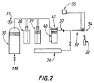
- the gaseous mixture (principally VOCs, VOXs, hydrogen and oxygen) produced by the electro-oxidation reaction accumulates in an expansion reservoir 30, at the top of which a valve is preferably provided for the escape of the gases when the pressure inside the reservoir reaches a given value so as to compensate for any pressure drops in the supply circuit of the combustion unit, a pressure detector 31 being provided in order to measure the pressure at the output from the reservoir 30.
- this pressure is around 100 mbar.
- the gaseous mixture is channelled to the combustion unit, comprising principally a burner 32 formed typically by a burner nozzle whose diameter is chosen according to the flow of gaseous mixture so as to ensure a sufficient speed of gas flow into the burner.
- a burner is used whose diameter is around 0.5 mm, which permits a gaseous mixture speed of between 20 and 30 m/s.
- the speed of the gas flow must be greater than the speed of movement of the flame in the burner so as to prevent flash-back to the reservoir 30.
- the speed of the flame at ambient pressure is around 19 m/s.
- the initial temperature of the gaseous mixture coming from the reservoir 30 is sufficiently low (generally below 50°C), which, for many organic gases and compounds, is significantly lower than the auto-ignition temperature (typically above 250°C).
- means 33 are disposed (an automatic-ignition torch, for example) for initiating the combustion of the mixture.
- the VOCs and VOXs are then transformed by thermal combustion into acids of low molecular weight (HCl, HBr, HI, etc), and into carbon dioxide, sulphur dioxide and nitrogen. No other additional treatment (except, optionally, an alkaline trap for neutralizing acidic discharges and other by-products) is required at the outlet from the combustion unit.
- a platinum filament 34 (in the form of a coil) is disposed at the outlet of the burner 32.
- the platinum filament has a number of functions. Firstly, it enables the flame to be re-ignited if it is extinguished following a disturbance (by an air current, for example) in the environment of the burner 32. Furthermore, because of its colour during combustion (substantially red), it provides an operator with a signal that combustion has indeed taken place, which, for certain flame colours (blue, notably), could be difficult to see otherwise.
- the two ends of the platinum filament 34 are connected to means 35 for measuring the resistance in the coil 34, the said measured resistance being representative of the combustion temperature.
- the combustion temperature is an important parameter for the process since, at certain temperatures, the combustion of the VOCs and VOXs can generate undesirable substances. Thus the combustion temperature is preferably between 500 and 1300°C, so that the formation of nitrogen oxide is avoided.
- the combustion temperature can be adjusted in different ways.
- an air or oxygen input 36 with variable flow is used. This air or oxygen supply enables the temperature of the gaseous mixture to be cooled down and its hydrogen level reduced, thereby lowering the combustion temperature. The reaction can thus be halted by cooling the mixture sufficiently.
- This input also enables all or part of the quantity of oxygen required for combustion to be supplied, when the gaseous mixture contained in the reservoir 30 does not contain any oxygen, or at least not in sufficient quantities.
- the safety of the system is further increased by inserting a certain number of safety devices in the supply circuit of the combustion unit.
- a flame arrester 37 At the inlet to the combustion unit, there is disposed a flame arrester 37.
- These devices are well known, and include, for example, a device of the honeycomb type designed to prevent the propagation of a flame coming from the burner.
- Other cooling systems can be envisaged.
- a cooling circuit in the form of a coil immersed in a cooling liquid is used.
- a plurality of non-return devices 38, 39, 40 disposed in series between the reservoir 30 and the burner 32 are used.
- two hydraulic non-return devices 39, 40 designed to isolate the reservoir 30 from the combustion unit, are used.
- the device 40 has a safety valve of the bursting disk type, enabling physical damage to be minimized in the event of an abnormal increase in volume or pressure, caused either by excess pressure in the reservoir, should there be a fault in the electro-oxidation device, or by an ignition of the gaseous mixture between the burner and the non-return device 40, if the flame arrester and electro-oxidation device should fail.
- the invention that has been described is particularly advantageous in that it provides a simple, risk-free solution to the problem of destroying undesirable reaction gases such as VOCs and VOXs. Furthermore, it enables the risk associated with the destruction of hydrogen generated by reactions such as electro-oxidation reactions to be reduced to the maximum possible extent.
Landscapes
- Engineering & Computer Science (AREA)
- Chemical & Material Sciences (AREA)
- Mechanical Engineering (AREA)
- General Engineering & Computer Science (AREA)
- Environmental & Geological Engineering (AREA)
- Chemical Kinetics & Catalysis (AREA)
- Combustion & Propulsion (AREA)
- Physical Or Chemical Processes And Apparatus (AREA)
- Electrolytic Production Of Non-Metals, Compounds, Apparatuses Therefor (AREA)
- Incineration Of Waste (AREA)
Claims (8)
- Verfahren zum Zersetzen einer mindestens einen fotografischen Entwickler umfassenden fotografischen Lösung, gekennzeichnet durch die Schritte:Elektrooxydieren der mindestens einen fotografischen Entwickler umfassenden fotografischen Lösung zum gleichzeitigen Zersetzen des fotografischen Entwicklers in mindestens eine flüchtige organische Verbindung und zum Herstellen eines Wasserstoff und Sauerstoff enthaltenden Gemischs von Reaktionsgasen aus der fotografischen Lösung,Überführen des während der Elektrooxydation erzeugten Gemischs aus Reaktionsgasen in ein Ausdehnungsgefäß undVerbrennen des Gemischs aus Reaktionsgasen in einer gegenüber dem Ausdehnungsgefäß isolierten Brennkammer.
- Vorrichtung zum Zersetzen einer mindestens einen fotografischen Entwickler umfassenden fotografischen Lösung durch Elektrooxydation, gekennzeichnet durcha) ein Elektrooxydationsgefäß (1-5; 7-9), durch das gleichzeitig der fotografische Entwickler in mindestens eine flüchtige organische Verbindung zersetzbar ist und Wasserstoff und Sauerstoff herstellbar sind,b) ein Ausdehnungsgefäß (30), welches das vom Elektrooxydationsgefäß erzeugte Gasgemisch enthält, undc) eine mit einem Brenner (32) versehene Brennkammer (32-35), welche mit dem Gasgemisch aus dem Ausdehnungsgefäß gespeist ist, und weiterhin gekennzeichnet durchd) ein Mittel (33) zum Einleiten der Verbrennung des Gasgemischs unde) Mittel zum Isolieren der Brennkammer gegenüber dem Ausdehnungsgefäß.
- Vorrichtung nach Anspruch 2, dadurch gekennzeichnet, dass die Brennkammer eine Platinspule (34) aufweist, welche in der Nähe des Brenners (32) angeordnet und derart aufgebaut ist, dass sie den Verbrennungsvorgang in Gang hält und beendet.
- Vorrichtung nach Anspruch 3, dadurch gekennzeichnet, dass die beiden Spulenenden an ein Mittel (35) zum Messen des Widerstands der Spule (34) angeschlossen sind, wobei der Widerstand von der Verbrennungstemperatur des Gasgemischs abhängt.
- Vorrichtung nach einem der Ansprüche 2 bis 4, dadurch gekennzeichnet, dass die Brennkammer einen mit dem Brenner verbundenen Luft- oder Sauerstoffeinlass (36) aufweist, dessen Durchfluss derart veränderbar ist, dass wahlweise ein für die Verbrennung erforderlicher zusätzlicher Sauerstoffvorrat bildbar oder die Verbrennung anhaltbar ist.
- Vorrichtung nach einem der Ansprüche 2 bis 5, dadurch gekennzeichnet, dass das Mittel zum Isolieren der Brennkammeres gegenüber dem Ausdehnungsgefäß eine Vielzahl hydraulischer Rückschlagvorrichtungen (39, 40) aufweist, welche in Reihe zwischen dem Ausdehnungsgefäß und der Brennkammer angeordnet sind, und dass ein Mittel (38) zwischen den hydraulischen Rückschlagvorrichtungen und dem Ausdehnungsgefäß angeordnet ist, welches verhindert, dass ein Rückfluss von Wasser in das Ausdehnungsgefäß erfolgt.
- Vorrichtung nach Anspruch 6, dadurch gekennzeichnet, dass auf den hydraulischen Rückschlagvorrichtungen Mittel (40; 41) vorgesehen sind, welche die Auswirkungen von Überdruck oder übermäßiger Ausdehnung des Gasvolumens über der Brennkammer einschränken.
- Vorrichtung nach einem der Ansprüche 2 bis 7, dadurch gekennzeichnet, dass eine Flammensperrvorrichtung (37) am Einlass zur Brennkammer angeordnet ist.
Applications Claiming Priority (2)
| Application Number | Priority Date | Filing Date | Title |
|---|---|---|---|
| FR9507168A FR2735213B1 (fr) | 1995-06-12 | 1995-06-12 | Procede et dispositif de destruction par incineration de gaz de reaction |
| FR9507168 | 1995-06-12 |
Publications (2)
| Publication Number | Publication Date |
|---|---|
| EP0748984A1 EP0748984A1 (de) | 1996-12-18 |
| EP0748984B1 true EP0748984B1 (de) | 2001-08-29 |
Family
ID=9480047
Family Applications (1)
| Application Number | Title | Priority Date | Filing Date |
|---|---|---|---|
| EP96420202A Expired - Lifetime EP0748984B1 (de) | 1995-06-12 | 1996-06-10 | Verfahren und Vorrichtung zur Vernichtung von Reaktionsgas durchVerbrennung |
Country Status (5)
| Country | Link |
|---|---|
| US (2) | US5948372A (de) |
| EP (1) | EP0748984B1 (de) |
| JP (1) | JPH0914631A (de) |
| DE (1) | DE69614769T2 (de) |
| FR (1) | FR2735213B1 (de) |
Cited By (2)
| Publication number | Priority date | Publication date | Assignee | Title |
|---|---|---|---|---|
| US9187347B2 (en) | 2002-11-19 | 2015-11-17 | Xogen Technologies Inc. | Treatment of a waste stream through production and utilization of oxyhydrogen gas |
| US9296629B2 (en) | 2002-11-19 | 2016-03-29 | Xogen Technologies Inc. | Treatment of a waste stream through production and utilization of oxyhydrogen gas |
Families Citing this family (9)
| Publication number | Priority date | Publication date | Assignee | Title |
|---|---|---|---|---|
| TW542886B (en) * | 2000-08-22 | 2003-07-21 | Ebara Corp | Method and device for combustion type exhaust gas treatment |
| KR100386125B1 (ko) * | 2001-01-12 | 2003-06-02 | (주)유니맥스 인터내셔널 | 수소가스를 이용한 고효율 병합 연소시스템 |
| KR20020094396A (ko) * | 2001-06-11 | 2002-12-18 | 신일균 | 가스 발생장치 |
| ATE455731T1 (de) | 2002-11-19 | 2010-02-15 | Xogen Technologies Inc | Abwässerbehandlung durch erzeugung und verbrauch von h2- und o2- gas |
| US7837882B2 (en) * | 2002-11-19 | 2010-11-23 | Xogen Technologies Inc. | Treatment of a waste stream through production and utilization of oxyhydrogen gas |
| US20080038592A1 (en) * | 2004-10-08 | 2008-02-14 | Harlan Anderson | Method of operating a solid oxide fuel cell having a porous electrolyte |
| DE102006014457A1 (de) * | 2006-03-29 | 2007-10-04 | Forschungszentrum Karlsruhe Gmbh | Verfahren zur thermischen Dehalogenierung von halogenhaltigen Stoffen |
| US8192693B2 (en) * | 2008-02-12 | 2012-06-05 | Innovative Engineering Solutions, Inc. | Apparatus for dynamic oxidation of process gas |
| US20100187321A1 (en) * | 2009-01-29 | 2010-07-29 | Randy Morrell Bunn | Home heating system utilizing electrolysis of water |
Family Cites Families (13)
| Publication number | Priority date | Publication date | Assignee | Title |
|---|---|---|---|---|
| US3925001A (en) * | 1969-12-19 | 1975-12-09 | Exxon Research Engineering Co | Placement of catalytically active materials in combustion flames |
| US3706662A (en) * | 1971-07-01 | 1972-12-19 | Walker L Wellford Jr | Non-polluting waste reducer and method |
| FR2235092A1 (en) * | 1973-06-29 | 1975-01-24 | Deflassieux Pierre | Incineration of waste water in combustion chamber - burning hydrogen with oxygen obtained by electrolysis of the water |
| US4089760A (en) * | 1974-08-30 | 1978-05-16 | Nippon Evr Limited | Method for regenerating waste developers used for processing silver halide photographic materials and method for storing developers |
| GB8414311D0 (en) * | 1984-06-05 | 1984-07-11 | Lovelock J E | Gas chromatography |
| US4941957A (en) * | 1986-10-22 | 1990-07-17 | Ultrox International | Decomposition of volatile ogranic halogenated compounds contained in gases and aqueous solutions |
| DE3642041A1 (de) * | 1986-12-09 | 1988-06-23 | Gerd Drespa | Verfahren zur aufarbeitung von altoel und altoelverarbeitungsanlage |
| DE3729113A1 (de) * | 1987-09-01 | 1989-03-09 | Fraunhofer Ges Forschung | Verfahren zur druckgesteuerten katalytischen verbrennung von brennbaren gasen in einem oxidationsreaktor |
| US5295448A (en) * | 1990-12-07 | 1994-03-22 | On-Demand Environmental Systems, Inc. | Organic compound incinerator |
| US5344630A (en) * | 1991-06-28 | 1994-09-06 | Rohm And Haas Company | Deep oxidation of halogenated organics with porous carbonaceous materials |
| US5160417A (en) * | 1991-09-11 | 1992-11-03 | Environmental Systems (International) Ltd. | Electrolytic process for treatment of photographic wastewater effluent |
| WO1995007373A1 (en) * | 1993-09-06 | 1995-03-16 | Hydrogen Technology Limited | Improvements in electrolysis systems |
| FR2731235B1 (fr) * | 1995-03-03 | 1997-04-25 | Kodak Pathe | Procede d'electro-oxydation de solutions photographiques |
-
1995
- 1995-06-12 FR FR9507168A patent/FR2735213B1/fr not_active Expired - Fee Related
-
1996
- 1996-06-10 DE DE69614769T patent/DE69614769T2/de not_active Expired - Fee Related
- 1996-06-10 EP EP96420202A patent/EP0748984B1/de not_active Expired - Lifetime
- 1996-06-11 US US08/665,067 patent/US5948372A/en not_active Expired - Fee Related
- 1996-06-11 JP JP8149270A patent/JPH0914631A/ja active Pending
-
1999
- 1999-04-15 US US09/292,216 patent/US6228250B1/en not_active Expired - Fee Related
Cited By (2)
| Publication number | Priority date | Publication date | Assignee | Title |
|---|---|---|---|---|
| US9187347B2 (en) | 2002-11-19 | 2015-11-17 | Xogen Technologies Inc. | Treatment of a waste stream through production and utilization of oxyhydrogen gas |
| US9296629B2 (en) | 2002-11-19 | 2016-03-29 | Xogen Technologies Inc. | Treatment of a waste stream through production and utilization of oxyhydrogen gas |
Also Published As
| Publication number | Publication date |
|---|---|
| US5948372A (en) | 1999-09-07 |
| FR2735213A1 (fr) | 1996-12-13 |
| DE69614769D1 (de) | 2001-10-04 |
| DE69614769T2 (de) | 2002-06-20 |
| FR2735213B1 (fr) | 1997-07-11 |
| US6228250B1 (en) | 2001-05-08 |
| EP0748984A1 (de) | 1996-12-18 |
| JPH0914631A (ja) | 1997-01-17 |
Similar Documents
| Publication | Publication Date | Title |
|---|---|---|
| EP0748984B1 (de) | Verfahren und Vorrichtung zur Vernichtung von Reaktionsgas durchVerbrennung | |
| US6875007B2 (en) | Multiple port catalytic combustion device and method of operating same | |
| US6635370B2 (en) | Shut-down procedure for hydrogen-air fuel cell system | |
| CN1216795C (zh) | 燃料改良系统及其控制 | |
| EP0716463A2 (de) | Polyelektrolytische Brennstoffzelle und Verfahren zur Betriebsteuerung | |
| JP2007517369A (ja) | 燃料電池スタックからの水の安全なパージ | |
| JP2003302494A (ja) | 気体の触媒酸化法と再結合装置及びシステム | |
| US8029736B2 (en) | High temperature decomposition of hydrogen peroxide | |
| KR100523783B1 (ko) | 연료 전지 장치 | |
| WO2002090249A1 (fr) | Appareil de formation d'hydrogene | |
| WO2004075327A3 (en) | Fuel cell system and fuel cell operating method | |
| CA2249581C (en) | Apparatus for treating air containing hydrogen gas | |
| US4951579A (en) | Low NOX combustion process | |
| KR100289986B1 (ko) | 수소함유배기가스 처리장치 | |
| JP2010238520A (ja) | 燃料電池システム | |
| JPH08197039A (ja) | アンモニア含有廃水の処理方法 | |
| Heck et al. | Hydrogen reduction following severe accidents using the dual recombiner—igniter concept | |
| WO2004067448A1 (en) | Decomposition of hydrogen peroxide and oxidation of nitric oxide | |
| KR20060029185A (ko) | 연료 처리 장치 및 그 방법 | |
| KR100692761B1 (ko) | 연료전지차량의 배기정화장치 | |
| WO2017061903A1 (ru) | Рекомбинатор и способ рекомбинации водорода или метана и кислорода в газовой смеси | |
| JPH0857256A (ja) | アンモニア分解装置 | |
| CN120204861A (zh) | 一种小风量voc废气处理系统 | |
| JPS63259970A (ja) | 燃料電池発電装置 | |
| JPH11240980A (ja) | 廃棄物用の熱分解炉 |
Legal Events
| Date | Code | Title | Description |
|---|---|---|---|
| PUAI | Public reference made under article 153(3) epc to a published international application that has entered the european phase |
Free format text: ORIGINAL CODE: 0009012 |
|
| AK | Designated contracting states |
Kind code of ref document: A1 Designated state(s): DE FR GB |
|
| 17P | Request for examination filed |
Effective date: 19970529 |
|
| 17Q | First examination report despatched |
Effective date: 19990708 |
|
| GRAG | Despatch of communication of intention to grant |
Free format text: ORIGINAL CODE: EPIDOS AGRA |
|
| GRAG | Despatch of communication of intention to grant |
Free format text: ORIGINAL CODE: EPIDOS AGRA |
|
| GRAH | Despatch of communication of intention to grant a patent |
Free format text: ORIGINAL CODE: EPIDOS IGRA |
|
| RAP1 | Party data changed (applicant data changed or rights of an application transferred) |
Owner name: EASTMAN KODAK COMPANY |
|
| GRAH | Despatch of communication of intention to grant a patent |
Free format text: ORIGINAL CODE: EPIDOS IGRA |
|
| GRAA | (expected) grant |
Free format text: ORIGINAL CODE: 0009210 |
|
| AK | Designated contracting states |
Kind code of ref document: B1 Designated state(s): DE FR GB |
|
| REF | Corresponds to: |
Ref document number: 69614769 Country of ref document: DE Date of ref document: 20011004 |
|
| ET | Fr: translation filed | ||
| REG | Reference to a national code |
Ref country code: GB Ref legal event code: IF02 |
|
| PLBE | No opposition filed within time limit |
Free format text: ORIGINAL CODE: 0009261 |
|
| STAA | Information on the status of an ep patent application or granted ep patent |
Free format text: STATUS: NO OPPOSITION FILED WITHIN TIME LIMIT |
|
| 26N | No opposition filed | ||
| PGFP | Annual fee paid to national office [announced via postgrant information from national office to epo] |
Ref country code: GB Payment date: 20040505 Year of fee payment: 9 |
|
| PGFP | Annual fee paid to national office [announced via postgrant information from national office to epo] |
Ref country code: FR Payment date: 20040602 Year of fee payment: 9 |
|
| PGFP | Annual fee paid to national office [announced via postgrant information from national office to epo] |
Ref country code: DE Payment date: 20040630 Year of fee payment: 9 |
|
| PG25 | Lapsed in a contracting state [announced via postgrant information from national office to epo] |
Ref country code: GB Free format text: LAPSE BECAUSE OF NON-PAYMENT OF DUE FEES Effective date: 20050610 |
|
| PG25 | Lapsed in a contracting state [announced via postgrant information from national office to epo] |
Ref country code: DE Free format text: LAPSE BECAUSE OF NON-PAYMENT OF DUE FEES Effective date: 20060103 |
|
| PG25 | Lapsed in a contracting state [announced via postgrant information from national office to epo] |
Ref country code: FR Free format text: LAPSE BECAUSE OF NON-PAYMENT OF DUE FEES Effective date: 20060228 |
|
| GBPC | Gb: european patent ceased through non-payment of renewal fee |
Effective date: 20050610 |
|
| REG | Reference to a national code |
Ref country code: FR Ref legal event code: ST Effective date: 20060228 |