EP0749083B1 - Verfahren und Einrichtung zur Frequenzspektrumbestimmung eines Signals - Google Patents
Verfahren und Einrichtung zur Frequenzspektrumbestimmung eines Signals Download PDFInfo
- Publication number
- EP0749083B1 EP0749083B1 EP96401223A EP96401223A EP0749083B1 EP 0749083 B1 EP0749083 B1 EP 0749083B1 EP 96401223 A EP96401223 A EP 96401223A EP 96401223 A EP96401223 A EP 96401223A EP 0749083 B1 EP0749083 B1 EP 0749083B1
- Authority
- EP
- European Patent Office
- Prior art keywords
- model
- order
- prediction
- sample
- coefficients
- Prior art date
- Legal status (The legal status is an assumption and is not a legal conclusion. Google has not performed a legal analysis and makes no representation as to the accuracy of the status listed.)
- Expired - Lifetime
Links
Images


Classifications
-
- G—PHYSICS
- G06—COMPUTING OR CALCULATING; COUNTING
- G06F—ELECTRIC DIGITAL DATA PROCESSING
- G06F17/00—Digital computing or data processing equipment or methods, specially adapted for specific functions
- G06F17/10—Complex mathematical operations
-
- G—PHYSICS
- G01—MEASURING; TESTING
- G01S—RADIO DIRECTION-FINDING; RADIO NAVIGATION; DETERMINING DISTANCE OR VELOCITY BY USE OF RADIO WAVES; LOCATING OR PRESENCE-DETECTING BY USE OF THE REFLECTION OR RERADIATION OF RADIO WAVES; ANALOGOUS ARRANGEMENTS USING OTHER WAVES
- G01S7/00—Details of systems according to groups G01S13/00, G01S15/00, G01S17/00
- G01S7/02—Details of systems according to groups G01S13/00, G01S15/00, G01S17/00 of systems according to group G01S13/00
- G01S7/41—Details of systems according to groups G01S13/00, G01S15/00, G01S17/00 of systems according to group G01S13/00 using analysis of echo signal for target characterisation; Target signature; Target cross-section
- G01S7/415—Identification of targets based on measurements of movement associated with the target
Definitions
- the autoregressive modeling analysis method consists in modeling a complex signal x (t) represented by a series of complex samples ⁇ x n ⁇ by means of a prediction law making it possible to deduce the value of a sample x n to starting from a linear combination of the values of the np previous samples of the sequence.
- Modeling is called autoregressive because, in the absence of noise and measurement errors on the samples, it is all the more faithful as the order p of the model is high. In practice noises and measurement errors cause the modeling to diverge so that we seek to limit the order p of modeling at the lowest value for which the modeling error is comparable to white noise.
- the autoregressive model defined below by the coefficients ⁇ a p, k ⁇ of the prediction law in the direct direction of the sample x n as a function of the np previous samples also has the property, which will be used in the following, of corresponding to a law of prediction in the retrograde direction of the sample x np as a function of the np following samples. Because we also have: where * denotes the conjugate operator and ⁇ b, n, p a prediction error in the retrograde direction of the model of order p on the value of the sample x np .
- Spectral analysis methods with an autoregressive model poses the problem of determining the sequence of complex coefficients ⁇ a p, k ⁇ defining the adopted model.
- a known solution is the method of least squares which is based on a minimization of the sum of the squares of prediction errors in the direct direction ⁇ f, n, p for n varying from 0 to N-p + 1, the samples x n being assumed to be zero outside the interval [1, N].
- the average of the sum of the error energies is:
- parameters ⁇ 0 and ⁇ 1 are chosen as a function of the type of application for a given measurement noise but are not very sensitive to errors of a factor 10.
- the parameter ⁇ 0 can be taken on the order of 1 and the parameter ⁇ 1 on the order of 0.001.
- the regularized least squares method developed by Kitagawa and Gersch lets you choose a prediction model order high under a constraint of spectral softness. However, it does not not suitable when the number of available signal samples is small. In this case, the Burg maximum entropy method is preferable because it is simpler to implement (no matrix inversion but only linear calculations) and more robust in the face of calculation noise and quantification and rounding errors.
- H p ( f ) H p-1 ( f ) + ⁇ p . e - j 2 ⁇ mp .
- Another object of the present invention is to regularize the Burg method which is less restrictive from the calculation point of view. Because we have seen that, if it were not for this need for regularization, the Burg method had the threefold advantage over the least squares method implantable in real time, at low computational cost, with a structure in trellis, to be generalizable to the crossover case introduced by Haykin in the case of frequency filtering or time smoothing of the analysis spectral and to be robust against computational noise, errors of quantification and rounding.
- ⁇ p being a reflection coefficient determined from the terms: where ⁇ f, n, p-1 denotes the prediction error, in the direct direction, by the prediction model of order p - 1, on the sample x n and ⁇ b, n-1, p-1 the error of prediction, in the retrograde direction, by the model of order p - 1, on the sample x np :
- This process is remarkable in that the reflection coefficient ⁇ p is determined by a relation of the form: where ⁇ 0 and ⁇ 1 are positive real coefficients.
- the invention also relates to a second method for determining the frequency spectrum of the mean of a family of I sampled signals ⁇ x n ⁇ i consisting in evaluating the coefficients ⁇ a p, k ⁇ of a prediction model d order p which correspond to a prediction law of the n th sample x i, n from the previous np samples ⁇ x i, nk ⁇ , k varying from 1 to p, of the form: where ⁇ f, i, n, p is a prediction error, in the direct sense, by the model of order p, of the sample x i, n of the signal i and which give an estimate of the average of the powers of the frequency spectra of the sampled signals in the form: where a p, 0 is worth 1 and where P I, p is the average of the powers of the direct prediction errors of the model of order p for the n th samples x i, n of the I signals when the model is reliable that is
- ⁇ f, i, n, p-1 denotes the prediction error, in the direct direction, by the prediction model of order p - 1, on the n th sample of the i th signal and ⁇ b, i, n -1, p-1 the prediction error, in the retrograde direction, by the model of order p - 1, on the n th sample of the i th signal:
- This process is remarkable in that the reflection coefficient ⁇ I, p is determined by a relation of the form: where ⁇ 0 and ⁇ 1 are positive real coefficients.
- the invention also relates to an implementation device of the first aforementioned process.
- This method of determining the reflection coefficient ⁇ p amounts to seeking a maximum of entropy, that is to say the minimization of the term: It has the disadvantage of having a reliability that is very sensitive to the choice of the order p of the prediction model, an order that is too weak giving an estimate of the frequency spectrum that is too rough, not reproducing all the existing peaks while an order that is too high. induces parasitic peaks in the estimation of the frequency spectrum.
- H p (f) is the transfer function of the predictive filter associated with the predictive model of order p
- R p-1.0 can be developed as follows or : Gold : from where:
- the estimation of the average autoregressive filter given by the Burg algorithm crossover is "desensitized” if a high intensity target or more lower intensities occupy a non-negligible relative number of cells of the estimation window.
- the medium filter being unsuitable with respect to the clutter environment, target detection, at the filter output, is degraded or even absent.
- the weighting is expressed as follows: s j being equal to 1 if cell i of the estimation window contains only clutter and to 0 if cell i of the estimation window contains a target.
- U stat / p represents the statistical expectation of the total (and no longer average) power of the direct and retrograde prediction errors of the majority population of the estimation window, conditional on a priori knowledge of the variable to order p-1:
- This last relation makes it possible to calculate the average power error of estimation and to deduce therefrom an expression of the coefficient of crossover thinking with statistical data weighting coming from each cell based on the probability of this cell to belong to the clutter environment.
- Card [C] 2 I and that s i, k corresponds to cell k of the estimation window for the event C i .
- This implicit autocorrelation matrix corresponds exactly to the explicit autocorrelation matrix of the spectral analysis method at autoregressive predictive model obtained by regularized least squares developed by Kitagawa and Gersch.
- FIG. 1 illustrates the diagram of a circuit 1 for calculating the complex coefficients ⁇ a p, 0 , ..., a p, p ⁇ of a prediction model of order p from the reflection coefficients ⁇ 1 , ..., ⁇ p ⁇ , according to the Burg maximum entropy method regularized or not by the new proposed method.
- the first line which determines all the coefficients a k, 0 of index zero of all the predictive models of order 0 to p contains no operator since all these coefficients have a unit value.
- a * / 1.1 delivered by a multiplier ( ⁇ ) receiving on the one hand the term ⁇ 2 and on the other hand the term a 1.1 conjugated or ⁇ 1 conjugated delivered via a conjugated operator (* ) inserted between the entry of the term ⁇ 1 and the entry of the multiplier ( ⁇ ).
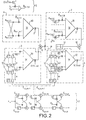
- FIG. 2 illustrates the diagram of a circuit for calculating a reflection coefficient ⁇ m , m varying from 1 to p, according to the new proposed method of regularization of the maximum Burgundy entropy method.
- This trellis filter 2 comprises a series of p identical stages defining two parallel paths, one on which the direct prediction errors ⁇ f, n, m , m varying from 1 to p are available, and the other on which are available the errors of retrograde predictions ⁇ b, n-1, m , m varying from 1 to p.
- Each stage has a two-input summator ( ⁇ ) on the direct prediction error channel, on the retrograde prediction error channel a delay cell (Z -1 ) delaying the error value of a signal sample , followed by a summator ( ⁇ ), and, between these two paths, two multipliers ( ⁇ ) performing the cross products, one of the direct prediction error available at the input of the floor with the conjugate of the coefficient of reflection ⁇ * m , m being the order of the stage, to apply it to the summator ( ⁇ ) of the path of the retrograde prediction error, the other of the retrograde prediction error available at the output of the delay cell of the stage with the reflection coefficient ⁇ m , m being the order of the stage, to apply it to the summator ( ⁇ ) of the path of the direct prediction error.
- circuits 3 and 4 for calculating the terms D * m and G m , m varying from 1 to p, the numerator and the denominator of the definition fraction of the reflection coefficient ⁇ m of Burg's maximum entropy method:
- the circuit 3 for calculating the term D * m comprises a summator 30 to Nm inputs connected to the outputs of the Nm last stages of two shift registers with N stages 31 and 32 via multiplier circuits (x) and conjugated operators (*).
- the shift register 31 is connected to the inputs of the summator 30 by conjugated operators (*) and multiplier circuits ( ⁇ ). It is connected by its serial input to the trellis filter 2, at the output of the m-1 th stage, on the way to the direct prediction error.
- the shift register 32 is connected to the inputs of the summator 30 only by the multiplier circuits ( ⁇ ) and is connected by its serial input to the trellis filter 2, between the delay circuit (Z -1 ) and the summator ( ⁇ ) of the m th stage, on the way to retrograde prediction error.
- a multiplier circuit ( ⁇ ) connected at the output of the summator 30 makes it possible to apply a weighting in 2 / (Nm) after the summation to obtain the term D * m .
- the circuit 4 for calculating the term G m comprises a summator 40 to 2 (Nm) inputs connected to the outputs of the Nm last stages of two shift registers with N stages 41 and 42 by means of individual circuits for calculating the square consisting of '' a multiplier circuit ( ⁇ ) with two inputs combined with a conjugated operator (*) inserted in one of its inputs.
- One 41 of the shift registers is connected by its serial input to the trellis filter 2, at the output of the m-1 th stage, on the path of the direct prediction error while the other shift register 42 is connected by its serial input to the trellis filter 2, between the delay circuit (Z -1 ) and the summator ( ⁇ ) of the m th stage, on the way to the retrograde prediction error.
- a multiplier circuit ( ⁇ ) connected at the output of the summator 40 makes it possible to apply a weighting in 1 / (Nm) after the summation to obtain the term G m .
- calculation circuits 1, 2, 3 and 4 which are found in the devices for real-time implementation of spectral analysis by the non regularized Burg entropy maximum method, we find specific calculation circuits 5, 6 and 7 enabling the implementation of the new regularization process proposed.
- the calculation circuits 5 make it possible to calculate intermediate parameters ⁇ m-1, k while the calculation circuits 6 and 7 make it possible to calculate the corrective regularization terms to be applied to the numerator and to the denominator of the definition fraction of the reflection coefficient ⁇ m.
- the calculation circuit 6 makes it possible to calculate the corrective term: applied to the numerator of the quotient defining the reflection coefficient ⁇ m . It consists of a summator 60 with m-1 entries, the k th entry receiving the coefficient a m-1, k via two multipliers ( ⁇ ) arranged in succession, one performing a product by the coefficient a m-1, mk , the other produced by ⁇ m-1, k .
- a multiplier ( ⁇ ) placed at the output of the summator 60 makes it possible to apply a weighting by 2 to arrive at the complete expression of the corrective term of the numerator.
- the calculation circuit 7 makes it possible to calculate the corrective term: applied to the denominator of the quotient defining the reflection coefficient ⁇ m . It consists of a summator 70 with m-1 inputs, the k th input receiving the coefficient a m-1, k via an individual circuit for calculating the square consisting of a multiplier circuit ( ⁇ ) with two inputs combined with a combined operator (*) inserted in one of its inputs. A multiplier ( ⁇ ) placed at the output of the summator 70 makes it possible to apply a weighting by 2 to arrive at the complete expression of the corrective term of the denominator.
- the outputs of calculation circuits 3 and 6 on which the term D * m of the numerator of the definition quotient of the reflection coefficient ⁇ m is available in the Burg maximum entropy method and the corrective term of this numerator for regularization are connected to the two inputs of an adder 8 fitted at the output of a multiplier circuit ( ⁇ ) 9 operating a multiplication by -1 to take account of the minus sign appearing in the definition quotient of the reflection coefficient.
- the regularized term of the numerator of its definition quotient, available at the output of the multiplier circuit 9, is divided by the regularized term of the denominator of its definition quotient, available at the output of the summator 10, at by means of a multiplier circuit 11 with two inputs, one of which is connected directly to the output of the multiplier circuit 9 and the other of which is connected to the output of the adder 10 via an inverter circuit 12.
- Figures 3, 4 and 5 show the different frequency spectra obtained by the respectively non regularized Burg method, regulated by the minimum free energy process and regulated by the proposed new method, for a complex signal having two lines frequency from which ten samples were taken in ten noisy prints regularly distributed.
- FIG. 5 which represents the spectra obtained for the ten noisy prints by implementing the Burg method up to the maximum possible order of nine, with a regularization according to the new proposed method taking into account a coefficient ⁇ 0 equal to 1 and a coefficient ⁇ 1 equal to 0.001, it can be seen that the different spectra only present the two lines actually existing with minor undulations.
- this new regularization process has caused less attenuation of the two frequency lines actually existing and better attenuation of the parasitic frequency lines. So it is better.
Landscapes
- Engineering & Computer Science (AREA)
- Physics & Mathematics (AREA)
- General Physics & Mathematics (AREA)
- Data Mining & Analysis (AREA)
- Theoretical Computer Science (AREA)
- Mathematical Physics (AREA)
- Mathematical Optimization (AREA)
- Databases & Information Systems (AREA)
- Algebra (AREA)
- Mathematical Analysis (AREA)
- Remote Sensing (AREA)
- Radar, Positioning & Navigation (AREA)
- Pure & Applied Mathematics (AREA)
- Computational Mathematics (AREA)
- Software Systems (AREA)
- General Engineering & Computer Science (AREA)
- Computer Networks & Wireless Communication (AREA)
- Management, Administration, Business Operations System, And Electronic Commerce (AREA)
- Compression, Expansion, Code Conversion, And Decoders (AREA)
- Complex Calculations (AREA)
Claims (4)
- Verfahren zur Bestimmung des Frequenzspektrums eines physikalischen getasteten Signals {xn}, das darin besteht, die Koeffizienten {ap,k} eines Vorhersagemodells der Ordnung p zu ermitteln, die einem Vorhersagegesetz für die n-te Tastprobe xn ausgehend von den n-p vorausgegangenen Tastproben {xn-k} entsprechen, wobei k von 1 bis p variiert, gemäß der Formelwobei εf,n,p ein Vorhersagefehler durch das Modell der Ordnung p in direkter Richtung für die Tastprobe xn ist, und die einen Schätzwert für die Leistung des Frequenzspektrums des getasteten Signals gemäß folgender Formel ergeben:
 wobei ap,0 den Wert 1 hat und Pp die Leistung des direkten Vorhersagefehlers des Modells der Ordnung p für die Tastprobe xn ist, wenn das Modell brauchbar ist, das heißt, wenn der Fehler ein weißes Rauschen ist, ausgehend von einem Rekurrenzgesetz der Ordnung p für das Modell gemäß folgender Form:
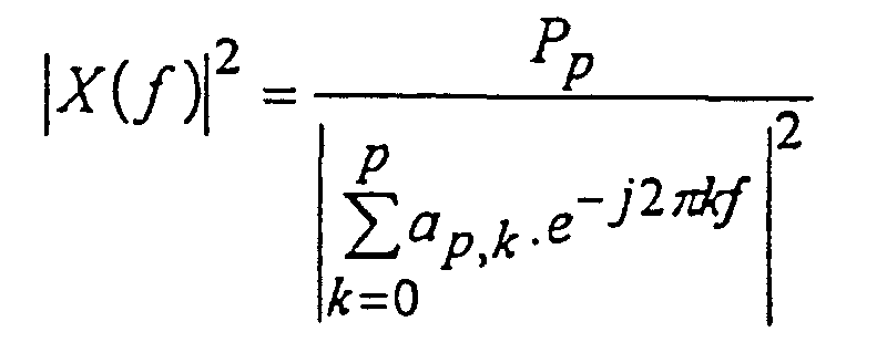
mit ap,0 = 1; ap-1,0 = 1 und k ∈ [1,...(p-1)],
wobei µp ein Reflexionskoeffizient ist, der durch die folgenden Größen bestimmt wird:wobei εf,n,p-1 der Vorhersagefehler in direkter Richtung des Vorhersagemodells der Ordnung p-1 bezüglich der Tastprobe xn und εb,n-1,p-1 der Fehler der Vorhersage in Rückwärtsrichtung für das Modell der Ordnung p-1 bezüglich der Tastprobe xn-p ist, wie folgt: dadurch gekennzeichnet, daß der Reflexionskoeffizient µp durch eine Beziehung folgender Form bestimmt wird:
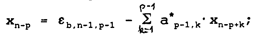 wobei λ0 und λ1 reelle positive Koeffizienten sind.
- Verfahren zur Bestimmung des Frequenzspektrums des Mittelwerts einer Familie von I physikalischen getasteten Signalen {xn}i, das darin besteht, die Koeffizienten {ap,k} eines Vorhersagemodells der Ordnung p zu ermitteln, die einem Vorhersagegesetz für die n-te Tastprobe xi,n ausgehend von den n-p vorausgegangenen Tastproben {xi,n-k} entsprechen,
wobei k von 1 bis p variiert, gemäß der Formel:wobei εf,i,n,p ein Vorhersagefehler des Modells der Ordnung p in direkter Richtung für die Tastprobe xi,n des Signals i ist, und die eine Schätzung für den Mittelwert der Leistungen der Frequenzspektren der getasteten Signale gemäß folgender Formel ergeben: wobei ap,0 den Wert 1 hat und PI,p der Mittelwert der Leistungen der direkten Vorhersagefehlers des Modells der Ordnung p für die n-ten Tastproben xi,n der I Signale ist, wenn das Modell brauchbar ist, das heißt, wenn die Fehler ein weißes Rauschen ergeben, ausgehend von einem Rekurrenzgesetz der Ordnung p für das Modell gemäß folgender Form:
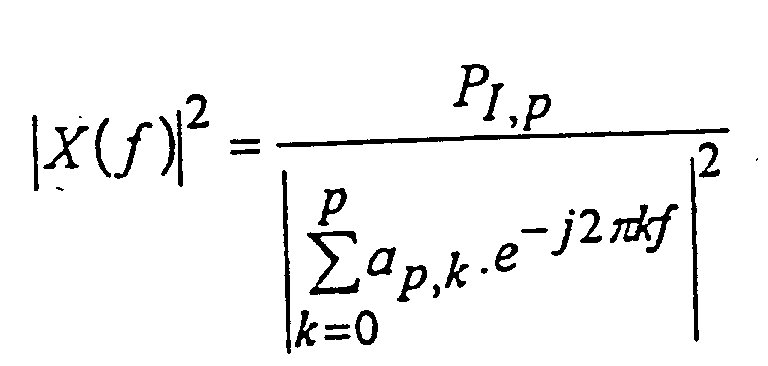
mit ap,0 = 1; ap-1,0 = 1 und k ∈ [1,...(p-1)],
wobei µI,p ein Reflexionskoeffizient ist, der durch die folgenden Größen bestimmt wird:wobei εf,i,n,p-1 der Vorhersagefehler in direkter Richtung des Vorhersagemodells der Ordnung p-1 bezüglich der n-ten Tastprobe des Signals I und εb,i,n-1,p-1 der Vorhersagefehler in Rückwärtsrichtung für das Modell der Ordnung p-1 bezüglich der (n-p)-ten Tastprobe des Signals I ist: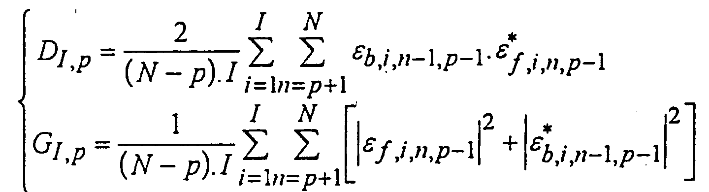 dadurch gekennzeichnet, daß der Reflexionskoeffizient µi,p durch eine Beziehung folgender Form bestimmt wird:
 wobei λ0 und λ1 reelle positive Koeffizienten sind.
- Verfahren zur Bestimmung des Frequenzspektrums des Mittelwerts einer Familie von I physikalischen getasteten Signalen {xn}i, das darin besteht, die Koeffizienten {ap,k} eines Vorhersagemodells der Ordnung p zu ermitteln, die einem Vorhersagegesetz für die n-te Tastprobe xi,n ausgehend von den n-p vorausgegangenen Tastproben {xi,n-k} entsprechen,
wobei k von 1 bis p variiert, gemäß der Formel:wobei εf,i,n,p ein Vorhersagefehler des Modells der Ordnung p in direkter Richtung für die Tastprobe xi,n des Signals i ist, und die eine Schätzung für den Mittelwert der Leistungen der Frequenzspektren der getasteten Signale gemäß folgender Formel ergeben: wobei ap,0 den Wert 1 hat und PI,p der Mittelwert der Leistungen der direkten Vorhersagefehler des Modells der Ordnung p für die n-ten Tastproben xi,n der Signale I ist, wenn das Modell brauchbar ist, das heißt, wenn die Fehler ein weißes Rauschen ergeben, ausgehend von einem Rekurrenzgesetz der Ordnung p für das Modell gemäß folgender Form:
mit ap,0 = 1; ap-1,0 = 1 und k ∈ [1,...(p-1)],
dadurch gekennzeichnet, daß der Reflexionskoeffizient µi,p durch eine Beziehung folgender Form bestimmt wird:mit wobei die Gewichtung K(χ2 i,p-1) durch folgenden Ausdruck gegeben ist
 wobei si = 1 gilt, wenn die Zelle i des Schätzfensters nur Störsignale enthält, und si = 0 gilt, wenn die Zelle i des Schätzfensters ein Ziel enthält, und wobei P(si=1) unabhängig vom Wert i der vorab bestimmten Wahrscheinlichkeit p1 gleicht, daß eine Zelle des Schätzfensters nur Störzeichen enthält, während P(si=0) unabhängig von i der vorab bestimmten Wahrscheinlichkeit gleicht, daß eine Zelle des Schätzfensters ein Ziel enthält, und wobei p1 und p0 durch die Beziehung p0 + p1 = 1 verknüpft sind, und wobei die Variable χ 2 i,p-1 folgenden Wert hat:
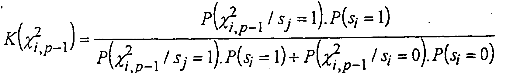 in dem εf,i,p-1 einen Vorhersagefehler in direkter Richtung des Vorhersagemodells der Ordnung p-1 bezüglich der n-ten Tastprobe des Signals I und εb,i,n-1,p-1 den Vorhersagefehler in Rückwärtsrichtung des Modells der Ordnung p-1 bezüglich der (n-p)-ten Tastprobe des Signals I bezeichnet:
 und wobei PI,p-1 der Mittelwert der Leistung der Vorhersagefehler des Modells der Ordnung p-1 ist.
- Vorrichtung zur Bestimmung des Frequenzspektrums einer physikalischen getasteten Signals {xn},wobei εf,n,p ein Vorhersagefehler des Modells der Ordnung p in direkter Richtung für die Tastprobe xn ist, und die Mittel aufweisen, um einen Schatzwert für die Leistung des Frequenzspektrums des getasteten Signals gemäß folgender Formel zu ergeben:mit ersten Rechenmitteln (1) zur Ermittlung der Koeffizienten {ap,1,...,ap,p} eines Vorhersagemodells der Ordnung p, die einem Vorhersagegesetz für die n-te Tastprobe xn ausgehend von den n-p vorausgegangenen Tastproben {xn-k} entsprechen, wobei k von 1 bis p variiert, gemäß der Formel
 wobei ap,o den Wert 1 hat und Pp die Leistung des direkten Vorhersagefehlers des Modells der Ordnung p für die Tastprobe xn ist, wenn das Modell brauchbar ist, das heißt, wenn der Fehler ein weißes Rauschen ist, ausgehend von einem Rekurrenzgesetz der Ordnung p für das Modell gemäß folgender Form:
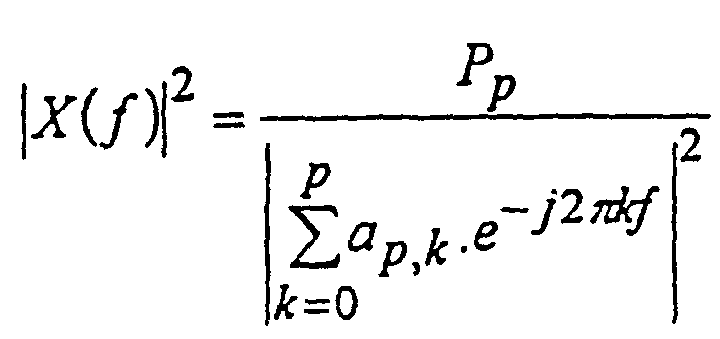
mit ap,0 = 1; ap-1,0 = 1 und k ∈ [1, ....p-1],
wobei µp ein Reflexionskoeffizient ist,wobei die Bestimmung der Fehler der direkten und rückwärtsgerichteten Vorhersage ausgehend von den Rekurrenzbeziehungen der Ordnung p des Modells erfolgt:mit zweiten Rechenmitteln (2), die die Struktur eines Filternetzes aufweisen, um die direkten Vorhersagefehler εf,n,m und die Fehler εb,n,m der rückwärts gerichteten Vorhersage zu bestimmen, wobei m von 1 bis p variiert und wobei ein Vorhersagefehler εb,n,m in Rückwärtsrichtung der Vorhersagefehler in Rückwärtsrichtung des Modells der Ordnung m für die Tastprobe xn-m ist: mit εf,n,0 = εb,n,0 = xn
 dadurch gekennzeichnet, daß sie außerdem aufweist:mit dritten Rechenmitteln (3) zur Bestimmung der Größen D*m, ausgehend von der Beziehung über die Fehler der direkten und rückwärtsgerichteten Vorhersage, wobei m von 1 bis p variiert:
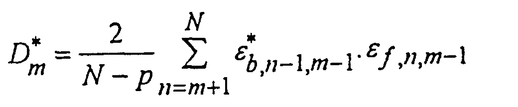 mit vierten Rechenmitteln (4) zur Bestimmung der Größen Gm, ausgehend von der Beziehung über die direkten und rückwärtsgerichteten Vorhersagefehler, wobei m von 1 bis p variiert:
 wobei λ0 und λ1 positive reelle Konstante sind,fünfte Rechenmittel (5) zur Berechnung von Zwischenparametern βm-1,k, wobei m von 1 bis p und k von 1 bis m-1 variiert, ausgehend von der Definitionsbeziehung:mit sechsten Rechenmitteln (6), die die Berechnung einer ersten korrigierenden Regulierungsgröße erlauben:welche auf den Wert der Größe D*m angewandt wird, der von den dritten Rechenmitteln berechnet wurde,
 und mit siebten Rechenmitteln (7), die die Berechnung einer zweiten korrigierenden Regulierungsgröße erlauben:die auf die Größe Gm angewandt wird, die von den vierten Rechenmitteln (4) berechnet wurde,
 und achte Rechenmittel (9, 10, 11, 12), die die Berechnung der Reflexionskoeffizienten µm ausgehend von den von den dritten, vierten, sechsten und siebten Rechenmitteln (3, 4, 6, 7) gelieferten Signalen gemäß folgender Beziehung erlauben:und wobei die ersten Rechenmittel (1) Mittel zur Berechnung der Koeffizienten {ap,1, ... ap,p} des Vorhersagemodells der Ordnung p unter Verwendung der Reflexionskoeffizienten µm enthalten.
Applications Claiming Priority (2)
| Application Number | Priority Date | Filing Date | Title |
|---|---|---|---|
| FR9506983A FR2735594B1 (fr) | 1995-06-13 | 1995-06-13 | Procede et dispositif de determination du spectre de frequence d'un signal |
| FR9506983 | 1995-06-13 |
Publications (2)
| Publication Number | Publication Date |
|---|---|
| EP0749083A1 EP0749083A1 (de) | 1996-12-18 |
| EP0749083B1 true EP0749083B1 (de) | 2002-08-28 |
Family
ID=9479909
Family Applications (1)
| Application Number | Title | Priority Date | Filing Date |
|---|---|---|---|
| EP96401223A Expired - Lifetime EP0749083B1 (de) | 1995-06-13 | 1996-06-07 | Verfahren und Einrichtung zur Frequenzspektrumbestimmung eines Signals |
Country Status (4)
| Country | Link |
|---|---|
| US (1) | US5729465A (de) |
| EP (1) | EP0749083B1 (de) |
| DE (1) | DE69623188T2 (de) |
| FR (1) | FR2735594B1 (de) |
Cited By (1)
| Publication number | Priority date | Publication date | Assignee | Title |
|---|---|---|---|---|
| CN110850162A (zh) * | 2019-11-22 | 2020-02-28 | 西南交通大学 | 基于误差相关熵的三相电力系统的频率估计方法 |
Families Citing this family (25)
| Publication number | Priority date | Publication date | Assignee | Title |
|---|---|---|---|---|
| US5893069A (en) * | 1997-01-31 | 1999-04-06 | Quantmetrics R&D Associates, Llc | System and method for testing prediction model |
| US6333986B1 (en) * | 1998-05-08 | 2001-12-25 | Lockheed Martin Corporation | Cepstral method and system for detecting/classifying objects from air-based or space-based images |
| FR2779548B1 (fr) | 1998-06-05 | 2000-11-10 | Thomson Csf | Procede de suivi dynamique de l'evolution de milieux deformables, et de prediction de leur evolution |
| FR2779549B1 (fr) | 1998-06-08 | 2000-09-01 | Thomson Csf | Procede de separation des composantes dynamique et statique d'une suite d'images |
| DE19934055C2 (de) | 1999-07-19 | 2001-06-13 | Siemens Ag | Verfahren zum Ermitteln von Amplitude und Phasenwinkel eines einem Strom oder einer Spannung eines elektrischen Energieversorgungsnetzes entsprechenden Meßsignals |
| US7554586B1 (en) | 1999-10-20 | 2009-06-30 | Rochester Institute Of Technology | System and method for scene image acquisition and spectral estimation using a wide-band multi-channel image capture |
| US8374218B2 (en) | 2000-12-05 | 2013-02-12 | Google Inc. | Combining signals with a shuffled-hadamard function |
| US8385470B2 (en) * | 2000-12-05 | 2013-02-26 | Google Inc. | Coding a signal with a shuffled-Hadamard function |
| US7453921B1 (en) * | 2001-12-11 | 2008-11-18 | Google Inc. | LPC filter for removing periodic and quasi-periodic interference from spread spectrum signals |
| KR20060044285A (ko) * | 2002-03-13 | 2006-05-16 | 레이씨언 캐나다 리미티드 | 위상 배열 방식 시스템용 잡음 억제 시스템 및 방법 |
| US6943724B1 (en) | 2002-10-30 | 2005-09-13 | Lockheed Martin Corporation | Identification and tracking of moving objects in detected synthetic aperture imagery |
| US7352833B2 (en) * | 2002-11-18 | 2008-04-01 | Google Inc. | Method and system for temporal autocorrelation filtering |
| US6864828B1 (en) | 2003-02-18 | 2005-03-08 | Lockheed Martin Corporation | Method and apparatus for collection and processing of interferometric synthetic aperture radar data |
| US7586436B2 (en) * | 2003-09-11 | 2009-09-08 | Mitsubishi Denki Kabushiki Kaisha | Radar device |
| US7792314B2 (en) * | 2005-04-20 | 2010-09-07 | Mitsubishi Electric Research Laboratories, Inc. | System and method for acquiring acoustic signals using doppler techniques |
| FR2890450B1 (fr) * | 2005-09-06 | 2007-11-09 | Thales Sa | Procede de determination par analyse doppler a haute resolution du champ de vitesse d'une masse d'air |
| US20070073797A1 (en) * | 2005-09-29 | 2007-03-29 | Lockheed Martin Corporation | Recursive method for solving the inexact greatest common divisor problem |
| FR2916280A1 (fr) * | 2007-05-15 | 2008-11-21 | Thales Sa | Procede de surveillance radar des turbulences de sillage |
| CN102590360A (zh) * | 2012-01-16 | 2012-07-18 | 电子科技大学 | 一种超声信号最小熵解卷积的无损检测方法 |
| US8816899B2 (en) * | 2012-01-26 | 2014-08-26 | Raytheon Company | Enhanced target detection using dispersive vs non-dispersive scatterer signal processing |
| US8976059B2 (en) | 2012-12-21 | 2015-03-10 | Raytheon Canada Limited | Identification and removal of a false detection in a radar system |
| CN107728124B (zh) * | 2017-09-08 | 2021-07-13 | 中国电子科技集团公司信息科学研究院 | 一种基于信息熵的多雷达动态调节方法及装置 |
| CN112014823B (zh) * | 2020-09-02 | 2022-04-01 | 中国人民解放军海军航空大学 | 基于目标幅度综合估计的自适应融合检测方法 |
| CN115242336B (zh) * | 2022-08-01 | 2023-02-03 | 北京航空航天大学 | 一种接收机射频前端器件的非线性输出频谱预测方法 |
| CN118869120B (zh) * | 2024-06-28 | 2025-08-29 | 武汉大学 | 一种侧信道矩信息最高阶数估测方法及系统 |
-
1995
- 1995-06-13 FR FR9506983A patent/FR2735594B1/fr not_active Expired - Fee Related
-
1996
- 1996-06-07 DE DE69623188T patent/DE69623188T2/de not_active Expired - Fee Related
- 1996-06-07 EP EP96401223A patent/EP0749083B1/de not_active Expired - Lifetime
- 1996-06-13 US US08/661,790 patent/US5729465A/en not_active Expired - Lifetime
Cited By (2)
| Publication number | Priority date | Publication date | Assignee | Title |
|---|---|---|---|---|
| CN110850162A (zh) * | 2019-11-22 | 2020-02-28 | 西南交通大学 | 基于误差相关熵的三相电力系统的频率估计方法 |
| CN110850162B (zh) * | 2019-11-22 | 2020-09-29 | 西南交通大学 | 基于误差相关熵的三相电力系统的频率估计方法 |
Also Published As
| Publication number | Publication date |
|---|---|
| FR2735594B1 (fr) | 1997-07-25 |
| DE69623188T2 (de) | 2003-07-17 |
| DE69623188D1 (de) | 2002-10-02 |
| US5729465A (en) | 1998-03-17 |
| EP0749083A1 (de) | 1996-12-18 |
| FR2735594A1 (fr) | 1996-12-20 |
Similar Documents
| Publication | Publication Date | Title |
|---|---|---|
| EP0749083B1 (de) | Verfahren und Einrichtung zur Frequenzspektrumbestimmung eines Signals | |
| EP2100161B1 (de) | Verfahren zur mehrwege-passivradar-verarbeitung eines fm-gelegenheitssignals | |
| EP2538409A1 (de) | Verfahren zur Geräuschdämpfung für Audio-Gerät mit mehreren Mikrofonen, insbesondere für eine telefonische Freisprechanlage | |
| EP1185000A1 (de) | Empfangseinrichtung für mobiles Funkkommunikationsgerät mit Geschwindigkeitsschätzer | |
| EP3238094B1 (de) | Verfahren zur nichtlinearen schätzung eines signalgemisches | |
| FR3020157A1 (fr) | Procede de detection numerique | |
| EP0729037B1 (de) | System zur Abschätzung von Empfangssignalen in einer Mischung von Signalen | |
| EP0903960B1 (de) | Antenne gebildet durch eine Vielzahl von akustischen Detektoren | |
| EP0166836B1 (de) | Verfahren zur Charakterisierung der Struktur eines Mediums und Vorrichtung dafür | |
| EP3671250B1 (de) | Digitales interferometer mit unterabtastung | |
| EP0410826B1 (de) | Iteratives Bewegungsabschätzungsverfahren zwischen einem Referenzbild und einem aktuellen Bild, und Verfahren zu ihrer Herstellung | |
| FR2699347A1 (fr) | Procédé et dispositif d'extraction d'un signal utile d'extension spatiale finie à chaque instant et variable avec le temps. | |
| EP0970562B1 (de) | Digitalfilter für fraktionale verzögerungen | |
| EP0958509B1 (de) | Vorrichtung zur sammlung seismischer daten | |
| EP3346389B1 (de) | Sofort-datenverarbeitung in einem erfassungssystem | |
| EP0533540A1 (de) | Internes Verbindungsverfahren für neuronale Netzwerke | |
| FR3084192A1 (fr) | Procede de rendu d'une scene tridimensionnelle, programme d'ordinateur et dispositif correspondants | |
| EP1155497B1 (de) | System und verfahren zum verarbeiten von antennensignalen | |
| FR2736161A1 (fr) | Procede et dispositif d'integration coherente multi-rafales pour radar doppler a impulsions | |
| FR3038391B1 (fr) | Procede et dispositif de traitement d'un signal spectral | |
| EP0740165B1 (de) | Signalbearbeitungsverfahren und Vorrichtung zum Entfernen von Mehrdeutigkeiten in einem Doppler-Radar | |
| EP1446898B1 (de) | Mehrweg-strahlempfangsvorrichtung | |
| EP1371958A1 (de) | Vorrichtung und Verfahren zum Extrahieren der spectralen Signatur eines punkförmigen Ziels | |
| FR3153424A1 (fr) | Procédé de détermination de la direction d'arrivée des trajets de signaux ionosphériques HF sur un réseau de N capteurs, programme d'ordinateur et dispositif associés | |
| FR2875912A1 (fr) | Procede et reconstruction d'echantillonnage non ambigu a partir de l'echantillonnage ambigu d'un signal et applications notamment aux radars doppler |
Legal Events
| Date | Code | Title | Description |
|---|---|---|---|
| PUAI | Public reference made under article 153(3) epc to a published international application that has entered the european phase |
Free format text: ORIGINAL CODE: 0009012 |
|
| AK | Designated contracting states |
Kind code of ref document: A1 Designated state(s): DE FR GB IT |
|
| 17P | Request for examination filed |
Effective date: 19970108 |
|
| GRAG | Despatch of communication of intention to grant |
Free format text: ORIGINAL CODE: EPIDOS AGRA |
|
| 17Q | First examination report despatched |
Effective date: 20010920 |
|
| GRAG | Despatch of communication of intention to grant |
Free format text: ORIGINAL CODE: EPIDOS AGRA |
|
| GRAH | Despatch of communication of intention to grant a patent |
Free format text: ORIGINAL CODE: EPIDOS IGRA |
|
| GRAH | Despatch of communication of intention to grant a patent |
Free format text: ORIGINAL CODE: EPIDOS IGRA |
|
| RAP1 | Party data changed (applicant data changed or rights of an application transferred) |
Owner name: THALES |
|
| GRAA | (expected) grant |
Free format text: ORIGINAL CODE: 0009210 |
|
| AK | Designated contracting states |
Kind code of ref document: B1 Designated state(s): DE FR GB IT |
|
| REG | Reference to a national code |
Ref country code: GB Ref legal event code: FG4D Free format text: NOT ENGLISH |
|
| REF | Corresponds to: |
Ref document number: 69623188 Country of ref document: DE Date of ref document: 20021002 |
|
| GBT | Gb: translation of ep patent filed (gb section 77(6)(a)/1977) |
Effective date: 20021125 |
|
| PLBE | No opposition filed within time limit |
Free format text: ORIGINAL CODE: 0009261 |
|
| STAA | Information on the status of an ep patent application or granted ep patent |
Free format text: STATUS: NO OPPOSITION FILED WITHIN TIME LIMIT |
|
| 26N | No opposition filed |
Effective date: 20030530 |
|
| REG | Reference to a national code |
Ref country code: FR Ref legal event code: CL |
|
| REG | Reference to a national code |
Ref country code: FR Ref legal event code: CL Ref country code: FR Ref legal event code: AU |
|
| PGFP | Annual fee paid to national office [announced via postgrant information from national office to epo] |
Ref country code: IT Payment date: 20090618 Year of fee payment: 14 |
|
| PGFP | Annual fee paid to national office [announced via postgrant information from national office to epo] |
Ref country code: GB Payment date: 20090603 Year of fee payment: 14 Ref country code: DE Payment date: 20090604 Year of fee payment: 14 |
|
| GBPC | Gb: european patent ceased through non-payment of renewal fee |
Effective date: 20100607 |
|
| REG | Reference to a national code |
Ref country code: FR Ref legal event code: ST Effective date: 20110228 |
|
| PG25 | Lapsed in a contracting state [announced via postgrant information from national office to epo] |
Ref country code: IT Free format text: LAPSE BECAUSE OF NON-PAYMENT OF DUE FEES Effective date: 20100607 |
|
| PG25 | Lapsed in a contracting state [announced via postgrant information from national office to epo] |
Ref country code: DE Free format text: LAPSE BECAUSE OF NON-PAYMENT OF DUE FEES Effective date: 20110101 |
|
| PG25 | Lapsed in a contracting state [announced via postgrant information from national office to epo] |
Ref country code: FR Free format text: LAPSE BECAUSE OF NON-PAYMENT OF DUE FEES Effective date: 20100630 |
|
| PG25 | Lapsed in a contracting state [announced via postgrant information from national office to epo] |
Ref country code: GB Free format text: LAPSE BECAUSE OF NON-PAYMENT OF DUE FEES Effective date: 20100607 |
|
| PGFP | Annual fee paid to national office [announced via postgrant information from national office to epo] |
Ref country code: FR Payment date: 20090611 Year of fee payment: 14 |