EP0749114A2 - Verfahren und System zum Regeln einer optischen Aufzeichnungsvorrichtung für ein optisches Aufzeichnungsmedium mit variierendem thermischen Eigenschaften - Google Patents
Verfahren und System zum Regeln einer optischen Aufzeichnungsvorrichtung für ein optisches Aufzeichnungsmedium mit variierendem thermischen Eigenschaften Download PDFInfo
- Publication number
- EP0749114A2 EP0749114A2 EP96650019A EP96650019A EP0749114A2 EP 0749114 A2 EP0749114 A2 EP 0749114A2 EP 96650019 A EP96650019 A EP 96650019A EP 96650019 A EP96650019 A EP 96650019A EP 0749114 A2 EP0749114 A2 EP 0749114A2
- Authority
- EP
- European Patent Office
- Prior art keywords
- optical disk
- information
- tuning
- fine
- portions
- Prior art date
- Legal status (The legal status is an assumption and is not a legal conclusion. Google has not performed a legal analysis and makes no representation as to the accuracy of the status listed.)
- Withdrawn
Links
Images





Classifications
-
- G—PHYSICS
- G11—INFORMATION STORAGE
- G11B—INFORMATION STORAGE BASED ON RELATIVE MOVEMENT BETWEEN RECORD CARRIER AND TRANSDUCER
- G11B7/00—Recording or reproducing by optical means, e.g. recording using a thermal beam of optical radiation by modifying optical properties or the physical structure, reproducing using an optical beam at lower power by sensing optical properties; Record carriers therefor
- G11B7/007—Arrangement of the information on the record carrier, e.g. form of tracks, actual track shape, e.g. wobbled, or cross-section, e.g. v-shaped; Sequential information structures, e.g. sectoring or header formats within a track
- G11B7/00736—Auxiliary data, e.g. lead-in, lead-out, Power Calibration Area [PCA], Burst Cutting Area [BCA], control information
-
- G—PHYSICS
- G11—INFORMATION STORAGE
- G11B—INFORMATION STORAGE BASED ON RELATIVE MOVEMENT BETWEEN RECORD CARRIER AND TRANSDUCER
- G11B7/00—Recording or reproducing by optical means, e.g. recording using a thermal beam of optical radiation by modifying optical properties or the physical structure, reproducing using an optical beam at lower power by sensing optical properties; Record carriers therefor
- G11B7/004—Recording, reproducing or erasing methods; Read, write or erase circuits therefor
- G11B7/005—Reproducing
-
- G—PHYSICS
- G11—INFORMATION STORAGE
- G11B—INFORMATION STORAGE BASED ON RELATIVE MOVEMENT BETWEEN RECORD CARRIER AND TRANSDUCER
- G11B7/00—Recording or reproducing by optical means, e.g. recording using a thermal beam of optical radiation by modifying optical properties or the physical structure, reproducing using an optical beam at lower power by sensing optical properties; Record carriers therefor
- G11B7/007—Arrangement of the information on the record carrier, e.g. form of tracks, actual track shape, e.g. wobbled, or cross-section, e.g. v-shaped; Sequential information structures, e.g. sectoring or header formats within a track
-
- G—PHYSICS
- G11—INFORMATION STORAGE
- G11B—INFORMATION STORAGE BASED ON RELATIVE MOVEMENT BETWEEN RECORD CARRIER AND TRANSDUCER
- G11B7/00—Recording or reproducing by optical means, e.g. recording using a thermal beam of optical radiation by modifying optical properties or the physical structure, reproducing using an optical beam at lower power by sensing optical properties; Record carriers therefor
- G11B7/007—Arrangement of the information on the record carrier, e.g. form of tracks, actual track shape, e.g. wobbled, or cross-section, e.g. v-shaped; Sequential information structures, e.g. sectoring or header formats within a track
- G11B7/00718—Groove and land recording, i.e. user data recorded both in the grooves and on the lands
-
- G—PHYSICS
- G11—INFORMATION STORAGE
- G11B—INFORMATION STORAGE BASED ON RELATIVE MOVEMENT BETWEEN RECORD CARRIER AND TRANSDUCER
- G11B7/00—Recording or reproducing by optical means, e.g. recording using a thermal beam of optical radiation by modifying optical properties or the physical structure, reproducing using an optical beam at lower power by sensing optical properties; Record carriers therefor
- G11B7/12—Heads, e.g. forming of the optical beam spot or modulation of the optical beam
- G11B7/125—Optical beam sources therefor, e.g. laser control circuitry specially adapted for optical storage devices; Modulators, e.g. means for controlling the size or intensity of optical spots or optical traces
- G11B7/126—Circuits, methods or arrangements for laser control or stabilisation
-
- G—PHYSICS
- G11—INFORMATION STORAGE
- G11B—INFORMATION STORAGE BASED ON RELATIVE MOVEMENT BETWEEN RECORD CARRIER AND TRANSDUCER
- G11B11/00—Recording on or reproducing from the same record carrier wherein for these two operations the methods are covered by different main groups of groups G11B3/00 - G11B7/00 or by different subgroups of group G11B9/00; Record carriers therefor
- G11B11/10—Recording on or reproducing from the same record carrier wherein for these two operations the methods are covered by different main groups of groups G11B3/00 - G11B7/00 or by different subgroups of group G11B9/00; Record carriers therefor using recording by magnetic means or other means for magnetisation or demagnetisation of a record carrier, e.g. light induced spin magnetisation; Demagnetisation by thermal or stress means in the presence or not of an orienting magnetic field
- G11B11/105—Recording on or reproducing from the same record carrier wherein for these two operations the methods are covered by different main groups of groups G11B3/00 - G11B7/00 or by different subgroups of group G11B9/00; Record carriers therefor using recording by magnetic means or other means for magnetisation or demagnetisation of a record carrier, e.g. light induced spin magnetisation; Demagnetisation by thermal or stress means in the presence or not of an orienting magnetic field using a beam of light or a magnetic field for recording by change of magnetisation and a beam of light for reproducing, i.e. magneto-optical, e.g. light-induced thermomagnetic recording, spin magnetisation recording, Kerr or Faraday effect reproducing
- G11B11/10502—Recording on or reproducing from the same record carrier wherein for these two operations the methods are covered by different main groups of groups G11B3/00 - G11B7/00 or by different subgroups of group G11B9/00; Record carriers therefor using recording by magnetic means or other means for magnetisation or demagnetisation of a record carrier, e.g. light induced spin magnetisation; Demagnetisation by thermal or stress means in the presence or not of an orienting magnetic field using a beam of light or a magnetic field for recording by change of magnetisation and a beam of light for reproducing, i.e. magneto-optical, e.g. light-induced thermomagnetic recording, spin magnetisation recording, Kerr or Faraday effect reproducing characterised by the transducing operation to be executed
-
- G—PHYSICS
- G11—INFORMATION STORAGE
- G11B—INFORMATION STORAGE BASED ON RELATIVE MOVEMENT BETWEEN RECORD CARRIER AND TRANSDUCER
- G11B11/00—Recording on or reproducing from the same record carrier wherein for these two operations the methods are covered by different main groups of groups G11B3/00 - G11B7/00 or by different subgroups of group G11B9/00; Record carriers therefor
- G11B11/10—Recording on or reproducing from the same record carrier wherein for these two operations the methods are covered by different main groups of groups G11B3/00 - G11B7/00 or by different subgroups of group G11B9/00; Record carriers therefor using recording by magnetic means or other means for magnetisation or demagnetisation of a record carrier, e.g. light induced spin magnetisation; Demagnetisation by thermal or stress means in the presence or not of an orienting magnetic field
- G11B11/105—Recording on or reproducing from the same record carrier wherein for these two operations the methods are covered by different main groups of groups G11B3/00 - G11B7/00 or by different subgroups of group G11B9/00; Record carriers therefor using recording by magnetic means or other means for magnetisation or demagnetisation of a record carrier, e.g. light induced spin magnetisation; Demagnetisation by thermal or stress means in the presence or not of an orienting magnetic field using a beam of light or a magnetic field for recording by change of magnetisation and a beam of light for reproducing, i.e. magneto-optical, e.g. light-induced thermomagnetic recording, spin magnetisation recording, Kerr or Faraday effect reproducing
- G11B11/10595—Control of operating function
-
- G—PHYSICS
- G11—INFORMATION STORAGE
- G11B—INFORMATION STORAGE BASED ON RELATIVE MOVEMENT BETWEEN RECORD CARRIER AND TRANSDUCER
- G11B20/00—Signal processing not specific to the method of recording or reproducing; Circuits therefor
- G11B20/10—Digital recording or reproducing
- G11B20/10009—Improvement or modification of read or write signals
-
- G—PHYSICS
- G11—INFORMATION STORAGE
- G11B—INFORMATION STORAGE BASED ON RELATIVE MOVEMENT BETWEEN RECORD CARRIER AND TRANSDUCER
- G11B7/00—Recording or reproducing by optical means, e.g. recording using a thermal beam of optical radiation by modifying optical properties or the physical structure, reproducing using an optical beam at lower power by sensing optical properties; Record carriers therefor
- G11B7/007—Arrangement of the information on the record carrier, e.g. form of tracks, actual track shape, e.g. wobbled, or cross-section, e.g. v-shaped; Sequential information structures, e.g. sectoring or header formats within a track
- G11B7/00745—Sectoring or header formats within a track
-
- G—PHYSICS
- G11—INFORMATION STORAGE
- G11B—INFORMATION STORAGE BASED ON RELATIVE MOVEMENT BETWEEN RECORD CARRIER AND TRANSDUCER
- G11B7/00—Recording or reproducing by optical means, e.g. recording using a thermal beam of optical radiation by modifying optical properties or the physical structure, reproducing using an optical beam at lower power by sensing optical properties; Record carriers therefor
- G11B7/08—Disposition or mounting of heads or light sources relatively to record carriers
- G11B7/09—Disposition or mounting of heads or light sources relatively to record carriers with provision for moving the light beam or focus plane for the purpose of maintaining alignment of the light beam relative to the record carrier during transducing operation, e.g. to compensate for surface irregularities of the latter or for track following
- G11B7/0901—Disposition or mounting of heads or light sources relatively to record carriers with provision for moving the light beam or focus plane for the purpose of maintaining alignment of the light beam relative to the record carrier during transducing operation, e.g. to compensate for surface irregularities of the latter or for track following for track following only
Definitions
- the current invention is generally related to a method and a system for fine-tuning input-output (I/O) operations involving an optical disk, and more particularly related to a method and a system for optimizing I/O operations on an optical disk that stores data in both land and groove portions.
- I/O input-output
- An optical disk system generally includes at least an optical disk medium, a laser light source and an input-output (I/O) controller unit.
- the optical disk medium stores information by changing the surface characteristics for the incident laser light so that the reflected light can be converted into electrical signals corresponding to the stored information.
- the optical disk system also includes an optical pick up unit and a servo device for moving the pick up unit over the disk surface.
- the I/O controller unit coordinates the activation and the deactivation of the above described components.
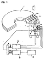
- the components include an optical disk 1, an optical pick-up unit 4, a servo controller 10, and a system input-output controller 20.
- the optical pick-up unit 4 further includes the laser source unit 5 for emitting a laser beam towards the optical disk 1 via a beam splitter 7 and an object lens 6.
- a focus actuator 13 positions the object lens 6 along the direction of the laser beam at a predetermined distance with respect to the laser light source 5.
- the focused laser beam is moved over the surface of the optical disk 1 along the radius of the disk 1 by a positioner 12 so that the beam approaches towards a desired track.
- a track actuator precisely positions the focused beam on the specified track.
- a servo controller 10 controls the above described servo mechanisms 11, 12 and 13.
- the focused laser beam incident upon a track is reflected back towards the optical pick-up unit 4.
- the reflected laser beam is diverted from the original beam axis by the beam splitter 7 towards an optical detector 8 for generating an electrical signal.
- the detected electrical signal is sent to a processing circuit 9 for further processing.
- the processing circuit 9 generates a focus error signal (FE) as well as a track error signal (TE) as necessary and sends these signals to the servo controller 10 for compensating the detected positional errors.
- the processing circuit 9 also generates a pit positional signal (PPS) for indicating the position and the optical signal (MOS) for representing the stored data at the position.
- PPS pit positional signal
- MOS optical signal
- the circuit 9 sends these signals to the I/O system controller 20 for further input-output operations with a host computer 30.
- the host computer 30 receives the data stored in the ptical disk as well as sends data to be stored in the disk at the specified addresses.
- read-write optical disks are generally optical in nature and include magnetooptical disks and phase change optical disks. These disks are constructed to have predetermined data storage areas such as a land portion 3 and a groove portion 2 as shown in Figure 1.
- the land and groove portions are adjacently located spiral tracks and have a pitch ranging from approximately 1.0 ⁇ m to approximately 1.8 ⁇ m.
- these two areas are constructed in such a way that the groove portion 2 is projecting towards and located closer to the laser source unit 5 than the land portion 3.
- the land portions 3 and the groove portions 2 are illustrated in a perspective view.
- either the land portion 3 or the groove portion 2 is used for storing data.
- the land portion 3 is used as a track for storing data while the groove portion 2 does not store data and is used for guiding the laser beam on the track.
- the reversed arrangement is also possible.
- the pitch of the tracks was decreased so that more tracks are defined per unit area.
- such thin tracks having a pitch of less than 1.4 ⁇ m caused a cross talk problem since a diameter of the focused laser beam was larger than a single track width and extended over the adjacent tracks. Consequently, the adjacent tracks interfered the reflection of the laser beam.
- the servo mechanism was prone to have more errors due to the increased requirement for accuracy in guiding the laser beam on narrower tracks.
- a laser source unit was modified to emit laser of a narrower wave length, such a laser source unit was more expensive and also lacked a sufficient emitting power.
- the width of the land portion 3 was constructed to be substantially the same as that of the groove portion 2 so as to read and record the data at an equivalent accuracy level.
- the width of either track is made at 0.7 ⁇ m with the pitch of 1.4 ⁇ m.
- the depth of the groove portion 2 is adjusted so that the reflected laser beam from the adjacent tracks are not at the same intensity. As a result, when the reflected beam is converted into an electrical signal, the interference from the adjacent tracks is reduced.
- the same input-output (I/O) operations produced undesirably different results between the land portions and the groove portions.
- the accuracy of data retrieval operations from the land portion is substantially different from that from the groove portion.
- the common principle of the optical I/O operations involves heating of the disk medium at predetermined temperatures and is referred to as a heat mode recording.
- the strength of a laser beam is accordingly adjusted.
- the penetrating laser beam generates sufficient energy in a recording layer of the optical disk to cause a certain phase shift, fusion or a change in an axis of magnetization. These changes are referred to as a mark and signifies the recorded data.
- the reflected laser beam should be strong enough to differentiate the marks from the non-marks so that a desirable carrier to noise ratio is ascertained.
- the reading laser strength should not change any marks.
- the relationship between the erasing laser strength the recording strength depends upon an optical method of choice. During the erasing operation, the polarity of an external magnet 16 is reversed from the polarity shown in FIGURE 1 when a magnetooptical disk is used.
- a cross sectional view of one example of a magnetooptical disk 1 shows a substrate portion 60 which is approximately 130 mm in diameter and made of photo polymer. Over the substrate portion 60, a recording layer 66 and a under protective layer 64 are spattered.
- the recording layer 66 is approximately 50 nm thick and made of TbFeCo while the under protective layer 64 is approximately 70 nm thick and made of SiN.
- a different composition of the layer materials generally possesses to a different heat characteristic or heat capacity. The heat capacity of the layer composition should be taken into consideration to determine the laser strength during the optical disk I/O operations.
- the disk is rotated at a constant angular velocity.
- the equivalent linear speed is different. Due to the different linear speed, a unit area in the peripheral and central regions receives a different amount of heat energy from the identical laser beam. Consequently, the laser beam at the same strength does not generate the same amount of heat in the peripheral region and the central region.
- the locality in the disk must be also considered to determine the laser strength for I/O operations on an optical disk.
- the laser power table is generated and stored in an external memory or on the same disk. Based upon the position of a specified track and an I/O operation to be performed, a stored value is selected to determine the laser strength.
- the environmental temperature also affects the laser strength for the optical disk I/O operations.
- the higher the room temperature the less energy from the laser beam is needed to achieve a predetermined temperature in a certain disk layer.
- a method of fine-tuning input-output (I/O) operations involving an optical disk medium includes the following steps of: a) storing information related to heat-characteristics of predetermined recordable portions of the optical disk medium; b) retrieving the information stored in the step a) for a selected one portion of the predetermined recordable portions; and c) adjusting an operational parameter based upon the information retrieved in the step b) so as to substantially improve the I/O operations involving the selected one portion of the optical disk medium.
- a method of adjusting input-output (I/O) operations involving an optical disk having a land portion and a groove portion includes the following steps of: a) storing separate heat-characteristic information for the groove portion and the land portion in combination with each of the I/O operations on the optical disk; b) determining a portion is wheter the land portion or the groove portion; c)selecting a combination of one of the portions and one of the I/O operations; d) retrieving the information stored in the step b) which corresponds to the combination selected in the step c); and e) adjusting an operational parameter based upon the information retrieved in the step d) so as to substantially optimize the selected I/O operation involving the selected portion of the optical disk.
- an optical disk includes: recordable data portions for storing data, the data portions having various heat characteristics; and information storage portions each associated with a corresponding one of the data portions for storing separate heat characteristic information.
- an optical disk includes: a land portion having a first heat characteristics for storing data; a groove portion located adjacent to the land portion having a second heat characteristics for storing data; and wherein a first table of adjustment values for compensating the first heat characteristics is stored on the land portion while a second table of adjustment values for compensating the second heat characteristics is stored on the groove portion.
- a system for adjusting an input-output (I/O) operational parameter for an optical recording device includes: an optical disk medium having predetermined recordable portions each having various heat characteristics; an adjustable laser source unit for emitting laser which ultimately reaches the optical disk medium; and an I/O controller unit connected to the adjustable laser source unit for modifying the I/O parameter which specifies the strength of the laser based upon the heat characteristics.
- a system for adjusting an input-output (I/O) operational parameter for an optical recording device incudes: an optical disk having predetermined portions including a land portion and a groove portion for recording data, the land portion having a first heat characteristic, the groove portion having a second heat characteristics, separate information for compensating the first heat characteristics and the second heat characteristics in combination with each of the I/O operations being stored in the optical disk; an I/O device for performing a selected I/O operation on a selected portion, the I/O device having an input including an operational parameter; and an I/O controller unit connected to the I/O device for modifying the operational parameter based upon the separate information so as to substantially optimize the selected I/O operation on the selected portion of the optical disk.
- FIGURE 1 diagrammatically illustrates a conventional optical storage system.
- FIGURE 2 illustrates marks stored on a land portion of a conventional optical disk.
- FIGURE 3 illustrates marks stored on a groove portion as well as a land portion of a conventional optical disk.
- FIGURE 4 is a cross sectional view of a magnetooptical disk medium.
- FIGURE 5 diagrammatically illustrates an optical storage system according to the current invention.
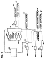
- FIGURE 6 diagrammatically illustrates some details of a servo controller as well as a land-groove determination unit according to the current invention.
- FIGURE 7A-C illustrate a polarity change in a tracking error signal used in a determining unit according to the current invention.
- FIGURES 8A-C illustrate how the polarity change in the tracking error signal is used to make a land-groove determination according to the current invention.
- FIGURE 9 diagrammatically illustrates one preferred embodiment of the circuit of a land-groove determination unit according to the current invention.
- FIGURE 10 is a conceptual graph illustrating how long the laser beam is casted on the optical disk medium based upon the laser power table according to the current invention.
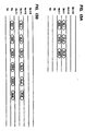
- FIGURES 11A-C illustrates an original signal to be recorded, the generated mark on the optical disk, and a play back signal generated based upon the mark so that an appropriate laser strength is determined for reading the data.
- FIGURE 12 illustrates one preferred embodiment of the magnetoptical disk having two spiral tracks each track segmented into a control information region and a data region according to the current invention.
- FIGURES 13A-B illustrate examples of the additional information for adjusting the laser strength according to the current invention.
- FIGURES 14A-B illustrate examples of the arrangements for storing the laser strength information according to the current invention.
- an optical disk storage system according to the current invention is generally similar to the one as described in FIGURE 1 in the Background section, and the descriptions of the identical components are not reiterated here.
- the optical disk 1 now contain data on both the land portion 3 and the groove portion 2.
- the marks are shown as dark dots or bands on these tracks.
- I/o operations are not as accurately performed as those when only one of the portions is used for the data storage.
- the I/O performance accuracy is maintained when either of the portions is used at a time for data storage.
- the same laser power table cannot be used for the two portions.
- two separate laser power tables 14 and 15 are provided in the I/O system controller 20 according to the current invention.
- the power table 14 contains adjustment values for adjusting the laser strength used during I/O operations on the land portion.
- the power table 15 contains separate adjustment vales for adjusting the laser strength used during I/O operations on the groove portion.
- the same inventive concept is implemented in a variety of other embodiments.
- the power tables 14 and 15 are merged into one table with two entries that contain separate laser power adjustment values respectively for the land and groove portions for a given I/O operation.
- a single table contains a set of adjustment values for the land portion and another set of coefficients for deriving a second set of adjustment values for the groove portion.
- the optical disk medium has two separate data storage portions, namely the land portion and the groove portion, the current invention is practiced with more than two predetermined data storage areas of varying characteristics.
- These characteristics include heat characteristics including heat capacity and heat conductivity of the recording layer as well as an expected amplitude of a given I/O signal, a mark width, a track width, and so on. Furthermore, some of these adjustment values are used for adjusting a gain in a wave form equalizer 100 for predetermined portions of the electrically converted optical signals.
- the above described varying characteristics are counter intuitive in view of the fact that the groove portion and the land portion are made from the same disk medium and the spattering process applies the same material.
- the surface compositions are assumed to be spattered unequally over the land portion and the groove portion. Because of the projection of the groove portion located adjacent to the land portion and the angle of the spattering is not perfectly parallel to the projection, the projection stands in the way to prevent some composition material from reaching certain areas of the disk surface. Consequently, not only the thickness of the layered composition but also the width of the spattered area appear to be different between the land portion and the groove portion.
- the above described separate sets of adjustment values are necessary to modify the laser strength to compensate for the unequal heat characteristics so that a given I/O operation performs substantially the same over the land and groove portions.
- a tracking error (T.E.) signal is inputted into a land track control circuit 31 and a groove control circuit 32, and the output from the respective circuits 31 and 32 is inputted into a first switching circuit 17.
- the first switching circuit 17 receives a controller output signal from a system controller 20, a polarity output signal from a tracking polarity detecting circuit 50 as well as an output from a track actuator forcing circuit 54.
- the combination of the polarity output signal and the controller signal determines the closing and opening of the first switch 17.
- the first switching circuit output 17 controls a track actuator 11 as well as a positioner 12 via a positioner control circuit 19.
- the focus error signal controls a focus actuator 13 via a focus control circuit 16 and a second switching circuit 18.
- the second switching circuit 18 receives a controller output from the system controller 20 and a sequence controller output from a sequence controller 24. The combination of the controller output and the sequence controller output determines the closing and the opening of the second switching circuit.
- the pit position signal (P.P.S.) is fed into an addressing circuit 21 to determine an address, and the output address is input the sequence controller 24.
- the ptical signal (M.O.S.) is inputted into an information generation circuit 22, and the output is also inputted into the sequence controller unit 24.
- the sequence controller unit 24 in turn controls a disk rotation motor 102 or interacts with a host computer 30.
- the X axis shows the movement an optical pickup unit along the radius of a ptical disk having land portions and track portions.
- the Y axis in FIGURE 7A shows that at a first level designated by (d) indicates the track is a land portion while at a second level designated by (e) indicates the track is a groove portion.
- the point (f) is a transition point between the land portion (d) and the groove portion (e).
- FIGURE 7B shows a change in reflection of the laser beam corresponding to the location indicated in FIGURE 7A.
- FIGURE 7C shows a tracking error signal which is generated based upon the push-pull method. The positive polarity of the tracking error signal indicates land tracking while the negative polarity indicates groove tracking.
- FIGURE 8A shows that the optical pick up unit moves along the radius of an optical disk having land portions and groove portions while the disk is rotated at a predetermined speed.
- the optical pick up path is a spiral crossing the land portions and the groove portions at a predetermined angle.
- the optical pick up is on a land track while at a point (e), it is on a groove track.
- the optical pick up is crossing from the land track into the groove track.
- FIGURE 8B shows a track actuator current.
- FIGURE 8C shows a tracking error signal which is generated by a push-pull method.
- the polarity of the tracking error signal is positive with respect to the track actuator current.
- the polarity of the tracking error signal is negative with respect to the track actuator current. Because these polarity corresponds to the position of the optical pick up unit with respect to the above described land and groove portions of the optical disk, the type of the track is detected. Based upon the detected type, the I/O process is performed with improved accuracy by adjusting the laser beam according to a selected adjustment value.
- the above described process of detection or determination is implemented in a detection circuit.
- a tracking error signal and an actuator driving signal are respectively inputted into hi-pass filters 51 and 52 of a predetermined threshold, and the phase of the outputs of the hi-pass filters 51 and 52 are compared by a phase comparator 53.
- the phase comparator outputs a positive signal when the phase of the two input signals matches while it outputs a negative signal when the phase fails to match.
- the circuit as described in FIGURE 9 determines whether the track is a land portion or a groove portion.
- a track can be determined to be a land portion or a groove portion according to alternative embodiments of the current invention.
- a predetermined table has been prepared to have a corresponding position signal value with an entry indicating the type of the track specified by the pit position signal.
- a process to determine the type of the track based upon the address which may be decoded by the pit position or specified by a host computer. Rather than storing types in a table, the type is mathematically determined by a predetermined calculating method such as MOD with a constant.
- the corresponding adjustment value or other correction information is retrieved for the specified portion of the optical disk, and a parameter such as an I/O function parameter value is accordingly modified prior to the execution of the I/O operation.
- a parameter such as an I/O function parameter value is accordingly modified prior to the execution of the I/O operation. For example, in order to record some data on a particular groove portion, an optical recording unit is moved towards the specified groove track and a servo mechanism tracks the movement. When the head reaches the specified groove track, the tracking servo is turned on and the track address is generated based upon the tracked data. If the generated track address fails to match the specified address, the servo tracking process is repeated until the addresses match.
- the data is first erased by beaming the specified track by emitting the laser at 1.2 times the optimal groove laser strength, An external magnet is reversed if a magnetooptical disk is used.
- a laser beam strength is adjusted to 0.9 times of the optimal laser beam strength for forming marks as indicated by Pw as wellas 0.1 times the same optimal value for not forming the marks as indicated by Pb during a write operation.
- a set of predetermined recording data is recorded on an optical disk and the recorded data is read from the disk to compare to the predetermined data for determining the accuracy of the I/O operations.
- a magnetoptical disk as described with respect to FIGURE 4 is rotated at 2400 rpm, and a laser beam having a wave length of 780 nm is emitted through an objective lens having a numerical aperture of 0.55. The laser beam is emitted towards the magnetoptical disk to raise the temperature in a recording layer while the external magnetization is exerted to flip the axis of magnetization.
- Data of frequency f0 and a duty of 50% as shown in FIGURE 11A is recorded as marks on the magnetoptical disk as shown in FIGURE 11B.
- a signal as shown in FIGURE 11C is generates. I/O parameters related to the laser generation are adjusted so as to make the duration of T1 substantially the same as that of T2.
- the recording laser power strength is defined to be optimal.
- the optimal recording laser strength is defined to be the laser strength when the secondary frequency 2f0 is minimal against the fundamental frequency f0.
- the following table shows the optimal recording laser strength for the land and groove portions at two different recording sites as specified by the distance from the rotational center along the radius:
- the optimal laser strength differs from a central region to a peripheral region of the disk due to a different angular speed of the disk where the laser beam is emitted. Because of the different angular speed, the same laser strength generates a different amount of heat in the recording layer in these regions.
- the optimal laser strength for the erasing process as well as that for the reading process are determined.
- the relationship among these laser strengths for the I/o operations is that the erasing laser level is generally higher than the recording laser level, and the reading laser level is usually lower than the recording laser level as described in the Background section.
- an optical disk is arranged into predetermined sectors for storing the above described optimal laser strength information rather than storing the laser power information in an external memory such as in the I/O system controller as shown in FIGURE 5.
- the adjacently located spiral tracks 2 and 3 are respectively the land portion and the groove portion. These tracks are divided into 12 sectors, and each sector contains an address portion such as portions 43 and 45 and a data portion such as portions 44 and 46.
- the above described laser strength information is stored at a predetermined location in the data portion according to this preferred embodiment. Such stored information is retrieved from the disk and used to adjust a certain I/O parameter prior to executing the corresponding I/O function for the specified track portion.
- tracks designated as 3n, 3n+1 and 3n+2 are control information tracks for the land portions.
- tracks designated as 4n, 4n+1 and 4n+2 are control information tracks for the groove portions.
- tracks 3n+1 contains three pieces of information labeled as DL1, DL2 and DL3 which respectively represent the recording, reading and erasing optimal laser power values for the land portion.
- tracks 4n+1 contains three pieces of information labeled as DG1, DG2 and DG3 which respectively represent the recording, reading and erasing optimal laser power values for the groove portion.
- FIGURE 13B illustrates that a second set of laser power values according to another embodiment of the current invention.
- DL4, DL5 and DL6 as well as DG4, DG5 and DG6 respectively contain a second set of laser power values for recording, reading and erasing at another site or region which is located at a different distance from the rotational axis along the radius from those locations optimized by the first set of laser power values, DL1, DL2 and DL3 as well as DG1, DG2 and DG3.
- the distance is further divided so as to specify three regions on the disk. In this case, the total of 18 individual laser power values is stored.
- other types of information are also helpful in optimizing the I/O performance.
- such other information includes a track width, a mark width, a recording layer thickness and a certain optical coefficient of the recording layer.
- the mark width determines an amount of heat necessary to accomplish a certain I/O function.
- This information is used to optimize the laser power strength or optimizing a wave form equalizer. Some or all of these information differ between the land portion and the groove portion. Some or all of these additional information also depend upon the location as to the distance from the rotational axis. According to FIGURES 14A and 14B, the above described information is stored on control information tracks of the optical disk.
- FIGURE 14A illustrates that a land portion of the control information track contains the above described information for the land portions at two different sites in the disk. Similarly, FIGURE 14A also illustrates that the groove portion contains two set of the additional information for the groove portions at two different locations on the disk. In contrast, FIGURES 14A and 14B show that the above described land and groove related information does not have to be stored in the corresponding track.
Landscapes
- Physics & Mathematics (AREA)
- Optics & Photonics (AREA)
- Optical Recording Or Reproduction (AREA)
Applications Claiming Priority (6)
| Application Number | Priority Date | Filing Date | Title |
|---|---|---|---|
| JP7147174A JPH08339583A (ja) | 1995-06-14 | 1995-06-14 | 光記録媒体 |
| JP147174/95 | 1995-06-14 | ||
| JP203026/95 | 1995-08-09 | ||
| JP7203026A JPH0954954A (ja) | 1995-08-09 | 1995-08-09 | 情報記録再生装置 |
| JP7208031A JPH0954955A (ja) | 1995-08-15 | 1995-08-15 | 光記録媒体 |
| JP208031/95 | 1995-08-15 |
Publications (2)
| Publication Number | Publication Date |
|---|---|
| EP0749114A2 true EP0749114A2 (de) | 1996-12-18 |
| EP0749114A3 EP0749114A3 (de) | 1998-02-25 |
Family
ID=27319313
Family Applications (1)
| Application Number | Title | Priority Date | Filing Date |
|---|---|---|---|
| EP96650019A Withdrawn EP0749114A3 (de) | 1995-06-14 | 1996-06-14 | Verfahren und System zum Regeln einer optischen Aufzeichnungsvorrichtung für ein optisches Aufzeichnungsmedium mit variierendem thermischen Eigenschaften |
Country Status (2)
| Country | Link |
|---|---|
| US (1) | US5793723A (de) |
| EP (1) | EP0749114A3 (de) |
Cited By (4)
| Publication number | Priority date | Publication date | Assignee | Title |
|---|---|---|---|---|
| EP0984441A1 (de) * | 1998-09-14 | 2000-03-08 | Matsushita Electric Industrial Co., Ltd. | Aufzeichnungsmedium, Aufzeichnungsgerät und Aufzeichnungsverfahren |
| WO2000054261A3 (en) * | 1999-03-08 | 2001-03-29 | Matsushita Electric Industrial Co Ltd | Recording drive information on recording medium |
| EP0905683A3 (de) * | 1997-09-26 | 2003-03-19 | Matsushita Electric Industrial Co., Ltd. | Optische Platte und Vorrichtung zur Wiedergabe und Aufzeichnung |
| CN101331546B (zh) * | 2005-12-12 | 2011-03-30 | 松下电器产业株式会社 | 激光能量控制方法以及光学信息记录再生装置 |
Families Citing this family (5)
| Publication number | Priority date | Publication date | Assignee | Title |
|---|---|---|---|---|
| JPH1186328A (ja) * | 1997-09-12 | 1999-03-30 | Asahi Optical Co Ltd | 光学式情報記録再生装置 |
| JP2001023237A (ja) * | 1999-07-02 | 2001-01-26 | Pioneer Electronic Corp | 情報記録媒体 |
| US7106673B2 (en) * | 2001-10-10 | 2006-09-12 | Teac Corporation | Optical disk recording apparatus with optimum power control |
| JP6035613B2 (ja) * | 2012-09-14 | 2016-11-30 | 株式会社日立製作所 | 光記録装置、光記録方法および光記録媒体 |
| CN109831398B (zh) * | 2018-12-29 | 2021-11-26 | 晶晨半导体(上海)股份有限公司 | 一种串行数据接收器的多级均衡器增益的自动调整方法 |
Family Cites Families (10)
| Publication number | Priority date | Publication date | Assignee | Title |
|---|---|---|---|---|
| US5410527A (en) * | 1985-05-14 | 1995-04-25 | Canon Kabushiki Kaisha | Information recording/reproducing apparatus including setting optimum recording condition or reproducing condition |
| JP2847722B2 (ja) * | 1988-06-24 | 1999-01-20 | ソニー株式会社 | 光磁気記録装置 |
| JP2773898B2 (ja) * | 1989-05-23 | 1998-07-09 | オリンパス光学工業株式会社 | 光学式情報記録/再生装置 |
| JP2576643B2 (ja) * | 1989-11-14 | 1997-01-29 | 三菱電機株式会社 | 光磁気記録装置 |
| JP2617010B2 (ja) * | 1990-02-28 | 1997-06-04 | シャープ株式会社 | 光磁気記録媒体及びその記録方法 |
| US5513165A (en) * | 1990-06-29 | 1996-04-30 | Hitachi, Ltd. | Method for controlling the farm of a magnetic domain of a magneto-optical disk using pre-write testing |
| US5590111A (en) * | 1990-06-29 | 1996-12-31 | Hitachi, Ltd. | Method of controlling recording of optical records |
| JP2809835B2 (ja) * | 1990-07-30 | 1998-10-15 | 松下電器産業株式会社 | 光ディスク装置および光ディスク |
| JP2697555B2 (ja) * | 1993-05-26 | 1998-01-14 | 松下電器産業株式会社 | 光情報記録媒体 |
| US5850378A (en) * | 1994-11-10 | 1998-12-15 | Matsushita Electric Industrial Co., Ltd. | Method and apparatus for recording data on an optical disk and or groove |
-
1996
- 1996-06-13 US US08/663,384 patent/US5793723A/en not_active Expired - Lifetime
- 1996-06-14 EP EP96650019A patent/EP0749114A3/de not_active Withdrawn
Cited By (24)
| Publication number | Priority date | Publication date | Assignee | Title |
|---|---|---|---|---|
| EP0905683A3 (de) * | 1997-09-26 | 2003-03-19 | Matsushita Electric Industrial Co., Ltd. | Optische Platte und Vorrichtung zur Wiedergabe und Aufzeichnung |
| US6157609A (en) * | 1998-09-14 | 2000-12-05 | Matsushita Electric Industrial Co., Ltd. | Recording medium, recording apparatus and recording method |
| WO2000016323A1 (en) * | 1998-09-14 | 2000-03-23 | Matsushita Electric Industrial Co., Ltd. | Recording medium, recording apparatus and recording method |
| EP0987692A1 (de) * | 1998-09-14 | 2000-03-22 | Matsushita Electric Industrial Co., Ltd. | Optisches Datenaufzeichnungsverfahren und Datenaufzeichnungsmedium |
| EP0987695A1 (de) * | 1998-09-14 | 2000-03-22 | Matsushita Electric Industrial Co., Ltd. | Optisches Datenaufzeichnungsverfahren und Datenaufzeichnungsmedium |
| EP0987693A1 (de) * | 1998-09-14 | 2000-03-22 | Matsushita Electric Industrial Co., Ltd. | Optisches Datenaufzeichnungsverfahren und Datenaufzeichnungsmedium |
| EP0987698A1 (de) * | 1998-09-14 | 2000-03-22 | Matsushita Electric Industrial Co., Ltd. | Aufzeichnungsmedium, Aufzeichnungsgerät und Aufzeichnungsverfahren |
| EP0987694A1 (de) * | 1998-09-14 | 2000-03-22 | Matsushita Electric Industrial Co., Ltd. | Optisches Datenaufzeichnungsverfahren und Datenaufzeichnungsmedium |
| US6175541B1 (en) | 1998-09-14 | 2001-01-16 | Matsushita Electric Industrial Co., Ltd. | Data recording medium and recording/reproducing apparatus for providing optimum position of mark start and end parts |
| EP0984441A1 (de) * | 1998-09-14 | 2000-03-08 | Matsushita Electric Industrial Co., Ltd. | Aufzeichnungsmedium, Aufzeichnungsgerät und Aufzeichnungsverfahren |
| WO2000016322A1 (en) * | 1998-09-14 | 2000-03-23 | Matsushita Electric Industrial Co., Ltd. | Optical data recording method, and data recording medium |
| EP0987697A1 (de) * | 1998-09-14 | 2000-03-22 | Matsushita Electric Industrial Co., Ltd. | Aufzeichnungsmedium, Aufzeichnungsgerät und Aufzeichnungsverfahren |
| US6101159A (en) * | 1998-09-14 | 2000-08-08 | Matsushita Electric Industrial Co. | Optical data recording method, and data recording medium |
| EP0987696A1 (de) * | 1998-09-14 | 2000-03-22 | Matsushita Electric Industrial Co., Ltd. | Optisches Datenaufzeichnungsverfahren und Datenaufzeichnungsmedium |
| US6178148B1 (en) | 1998-09-14 | 2001-01-23 | Matsushita Electric Industrial Co., Ltd. | Data recording medium and recording/reproducing apparatus for providing optimum position of mark start and end parts |
| US6181654B1 (en) | 1998-09-14 | 2001-01-30 | Matsushita Electric Industrial Co., Ltd. | Data recording medium and data recording/reproducing apparatus for providing optimum position of mark start and end parts |
| US6188656B1 (en) | 1998-09-14 | 2001-02-13 | Matsushita Electric Industrial Co., Ltd. | Optical data recording method, and data recording medium |
| EP0986054A1 (de) * | 1998-09-14 | 2000-03-15 | Matsushita Electric Industrial Co., Ltd. | Optisches Datenaufzeichnungsverfahren und Datenaufzeichnungsmedium |
| US6212142B1 (en) | 1998-09-14 | 2001-04-03 | Matsushita Electric Industrial Co., Ltd. | Data recording medium and recording/reproducing apparatus for providing optimum position of mark start and end parts |
| US6233211B1 (en) | 1998-09-14 | 2001-05-15 | Matsushita Electric Industrial Co., Ltd. | Data recording medium, recording/reproducing apparatus, manufacturing apparatus, and method for providing optimum position of mark start and end parts |
| US6349081B1 (en) | 1998-09-14 | 2002-02-19 | Matsushita Electric Industrial Co., Ltd. | Recording medium, recording apparatus and recording method |
| US6359846B1 (en) | 1998-09-14 | 2002-03-19 | Matsushita Electric Industrial Co., Ltd. | Recording medium recording apparatus and recording method |
| WO2000054261A3 (en) * | 1999-03-08 | 2001-03-29 | Matsushita Electric Industrial Co Ltd | Recording drive information on recording medium |
| CN101331546B (zh) * | 2005-12-12 | 2011-03-30 | 松下电器产业株式会社 | 激光能量控制方法以及光学信息记录再生装置 |
Also Published As
| Publication number | Publication date |
|---|---|
| EP0749114A3 (de) | 1998-02-25 |
| US5793723A (en) | 1998-08-11 |
Similar Documents
| Publication | Publication Date | Title |
|---|---|---|
| EP0164131B1 (de) | Informationsaufzeichnungsplatte und Verfahren und Gerät zum Aufzeichnen/Wiedergeben von Informationen | |
| US8072850B2 (en) | Optical information recording apparatus | |
| KR100937369B1 (ko) | 기록 장치 및 기록 방법 | |
| JP3142383B2 (ja) | 光学ディスク駆動装置におけるクロストーク低減方法 | |
| US20040052178A1 (en) | Information recording apparatus | |
| US5270987A (en) | Magneto-optical recording and reproducing method, magneto-optical memory apparatus and magneto-optical recording medium therefor | |
| US5793723A (en) | Method and a system for adjusting optical recording device involving an optical recording medium of non-uniform heat characteristics | |
| EP2189980A1 (de) | Optisches Aufzeichnungsmedium und optische Plattenvorrichtung | |
| US6744700B2 (en) | Optical output adjusting apparatus based on shortest recording marks | |
| US5696742A (en) | Optical disk device for reproducing address information from wobbled groove | |
| JP3265527B2 (ja) | 情報記録媒体 | |
| US20010028607A1 (en) | Reproduction power test method for domain-wall displacement type magneto-optical medium and optical information reproduction apparatus | |
| US4890274A (en) | Optical information recording and reproducing apparatus | |
| US8125865B2 (en) | Optical disc and optical disc apparatus | |
| US6016297A (en) | Information reproduction method and apparatus that move light beam toward outer perimeter of optical disk in response to tracking error | |
| US6259669B1 (en) | Technique for reducing cross erasure in an optical disc recording apparatus | |
| EP0762393B1 (de) | Erzeugung von Spurenzählimpulsen | |
| EP0393652B1 (de) | Magnetooptische Aufzeichnungs- und Wiedergabeverfahren, magnetooptische Speichervorrichtung | |
| US20050088954A1 (en) | Optical recording medium and optical storage device | |
| US20040081042A1 (en) | Optical disc drive | |
| EP0751505A2 (de) | Optisches Informationsaufzeichnungsmedium | |
| JPS61187139A (ja) | 光学的情報記録方法 | |
| US5621707A (en) | Method for erasing rewritable optical disk using two laser beams and an erasingspacehead therefor | |
| JP4338903B2 (ja) | 光ディスク記録装置およびその調整方法 | |
| WO2005043528A2 (en) | Method and apparatus for measuring the depth of a data record layer in an information record medium |
Legal Events
| Date | Code | Title | Description |
|---|---|---|---|
| PUAI | Public reference made under article 153(3) epc to a published international application that has entered the european phase |
Free format text: ORIGINAL CODE: 0009012 |
|
| AK | Designated contracting states |
Kind code of ref document: A2 Designated state(s): DE FR NL |
|
| PUAL | Search report despatched |
Free format text: ORIGINAL CODE: 0009013 |
|
| AK | Designated contracting states |
Kind code of ref document: A3 Designated state(s): DE FR NL |
|
| STAA | Information on the status of an ep patent application or granted ep patent |
Free format text: STATUS: THE APPLICATION IS DEEMED TO BE WITHDRAWN |
|
| 18D | Application deemed to be withdrawn |
Effective date: 19980826 |