EP0749224B1 - Mehrkanaliges faseroptisches Nachrichtenübertragungssystem mit einem Filter zur Kompensation der Wellenlängenabhängigkeit des wegen stimulierter Raman-Streuung Übersprechverhaltens - Google Patents
Mehrkanaliges faseroptisches Nachrichtenübertragungssystem mit einem Filter zur Kompensation der Wellenlängenabhängigkeit des wegen stimulierter Raman-Streuung Übersprechverhaltens Download PDFInfo
- Publication number
- EP0749224B1 EP0749224B1 EP96304021A EP96304021A EP0749224B1 EP 0749224 B1 EP0749224 B1 EP 0749224B1 EP 96304021 A EP96304021 A EP 96304021A EP 96304021 A EP96304021 A EP 96304021A EP 0749224 B1 EP0749224 B1 EP 0749224B1
- Authority
- EP
- European Patent Office
- Prior art keywords
- channels
- fiber
- wdm
- channel
- wavelength
- Prior art date
- Legal status (The legal status is an assumption and is not a legal conclusion. Google has not performed a legal analysis and makes no representation as to the accuracy of the status listed.)
- Expired - Lifetime
Links
- 239000013307 optical fiber Substances 0.000 title claims description 8
- 238000004891 communication Methods 0.000 title description 5
- 239000000835 fiber Substances 0.000 claims description 61
- 239000006185 dispersion Substances 0.000 claims description 41
- 238000007493 shaping process Methods 0.000 claims description 22
- 230000003321 amplification Effects 0.000 claims description 15
- 238000003199 nucleic acid amplification method Methods 0.000 claims description 15
- 238000001228 spectrum Methods 0.000 claims description 13
- 230000015556 catabolic process Effects 0.000 claims description 9
- 238000006731 degradation reaction Methods 0.000 claims description 9
- 230000003287 optical effect Effects 0.000 claims description 9
- 230000005540 biological transmission Effects 0.000 claims description 8
- 230000003595 spectral effect Effects 0.000 claims description 8
- 230000003247 decreasing effect Effects 0.000 claims description 4
- 238000013461 design Methods 0.000 description 16
- 230000006872 improvement Effects 0.000 description 10
- 238000001069 Raman spectroscopy Methods 0.000 description 9
- VYPSYNLAJGMNEJ-UHFFFAOYSA-N Silicium dioxide Chemical compound O=[Si]=O VYPSYNLAJGMNEJ-UHFFFAOYSA-N 0.000 description 8
- 238000013459 approach Methods 0.000 description 6
- 230000000694 effects Effects 0.000 description 5
- 238000001914 filtration Methods 0.000 description 5
- 238000003780 insertion Methods 0.000 description 5
- 230000037431 insertion Effects 0.000 description 5
- 238000000034 method Methods 0.000 description 5
- 239000000377 silicon dioxide Substances 0.000 description 4
- 230000001419 dependent effect Effects 0.000 description 3
- 230000009021 linear effect Effects 0.000 description 3
- 229910052691 Erbium Inorganic materials 0.000 description 2
- 230000008901 benefit Effects 0.000 description 2
- 238000004364 calculation method Methods 0.000 description 2
- 239000000969 carrier Substances 0.000 description 2
- 238000006243 chemical reaction Methods 0.000 description 2
- 239000011521 glass Substances 0.000 description 2
- 238000004088 simulation Methods 0.000 description 2
- 239000007787 solid Substances 0.000 description 2
- 238000012546 transfer Methods 0.000 description 2
- KRHYYFGTRYWZRS-UHFFFAOYSA-M Fluoride anion Chemical compound [F-] KRHYYFGTRYWZRS-UHFFFAOYSA-M 0.000 description 1
- 229910052777 Praseodymium Inorganic materials 0.000 description 1
- 230000004308 accommodation Effects 0.000 description 1
- 238000004458 analytical method Methods 0.000 description 1
- 238000005253 cladding Methods 0.000 description 1
- 239000011248 coating agent Substances 0.000 description 1
- 238000000576 coating method Methods 0.000 description 1
- 238000012937 correction Methods 0.000 description 1
- 230000008878 coupling Effects 0.000 description 1
- 238000010168 coupling process Methods 0.000 description 1
- 238000005859 coupling reaction Methods 0.000 description 1
- 239000013078 crystal Substances 0.000 description 1
- 230000006735 deficit Effects 0.000 description 1
- 238000011161 development Methods 0.000 description 1
- 238000010586 diagram Methods 0.000 description 1
- 238000005516 engineering process Methods 0.000 description 1
- UYAHIZSMUZPPFV-UHFFFAOYSA-N erbium Chemical compound [Er] UYAHIZSMUZPPFV-UHFFFAOYSA-N 0.000 description 1
- 238000012423 maintenance Methods 0.000 description 1
- 238000004519 manufacturing process Methods 0.000 description 1
- 230000007246 mechanism Effects 0.000 description 1
- 239000000203 mixture Substances 0.000 description 1
- 238000012986 modification Methods 0.000 description 1
- 230000004048 modification Effects 0.000 description 1
- 230000009022 nonlinear effect Effects 0.000 description 1
- PUDIUYLPXJFUGB-UHFFFAOYSA-N praseodymium atom Chemical compound [Pr] PUDIUYLPXJFUGB-UHFFFAOYSA-N 0.000 description 1
- 230000009467 reduction Effects 0.000 description 1
- 230000004044 response Effects 0.000 description 1
- 230000035945 sensitivity Effects 0.000 description 1
- 238000000926 separation method Methods 0.000 description 1
Images


Classifications
-
- H—ELECTRICITY
- H04—ELECTRIC COMMUNICATION TECHNIQUE
- H04B—TRANSMISSION
- H04B10/00—Transmission systems employing electromagnetic waves other than radio-waves, e.g. infrared, visible or ultraviolet light, or employing corpuscular radiation, e.g. quantum communication
- H04B10/25—Arrangements specific to fibre transmission
- H04B10/2507—Arrangements specific to fibre transmission for the reduction or elimination of distortion or dispersion
- H04B10/2537—Arrangements specific to fibre transmission for the reduction or elimination of distortion or dispersion due to scattering processes, e.g. Raman or Brillouin scattering
Definitions
- the chronicle of advances permitting state-of-the-art optical fiber communications systems includes:
- Typical state-of-the art systems in planning provide for 360km fiber spans including two EDFAs, 4-channel WDM operation, and 2.5Gbit per-channel operation to result in a system capacity of 10Gb. Greater system capacity - more channels and/or higher per-channel bit-rates - are permitted.
- the present invention provides a wavelength division multiplex optical waveguide system having the features recited in claim 1 of the accompanying claims.
- SRS crosstalk in WDM fiber systems is found to include a significant average deterministic component which may be the dominant SRS contribution. Appropriate spectral shaping suppresses this component.
- output of optical amplifiers is shaped by providing for decreasing amplification ratio for channels of increasing wavelength. Shaping may be by a fixed filter, without requirement for continuous adjustment.
- the invention impacts systems of capacity-length product sufficiently large to be capacity-limited by SRS.
- a threshold value for systems, of representative state-of-the-art parameters, to which the invention is usefully applied is expressed as the product of per-channel bit-rate, number of channels, and span length.
- Filter design suitable for a preferred embodiment may follow design principles used for flattening EDFA spectral output.
- SRS degradation caused by SRS may be greatly reduced by spectral shaping of the spectrum made up of a WDM channel set - e.g. by shaping the amplifier gain to favor the higher frequency, SRS-depleted, channels.
- Typical system design permits an improvement in capacity of five or more, allowing a system capacity of one hundred to a thousand or more gigabits/sec.
- EDFA Electronic Data Association
- FIG. 1 is representative of systems using the inventive procedure. It includes a transmitter 10 and receiver 11, together with an interconnecting transmission line 12 containing a number of amplifiers 13. Illustratively, each amplifier is accompanied by a filtering element 14. Optional regenerators 15 are shown in phantom. The implications of the invention pertain to each individual span without regard to number of spans. Successive spans are bounded by regenerators in multi-span systems. Under most circumstances, transmitter, receiver and regenerators include means for optical-to-electronic and/or electronic-to-optical signal conversion, functions requiring multiplexing and/or demultiplexing. In transmitter 10, channel carriers are produced by lasers 16, signal information is introduced by modulators 17, and signals are combined in multiplexer 18.
- receiver 11 Functions of receiver 11 are carried out by demultiplexer 19 and by individual channel detectors (optical-to-electronic converters) 20. Regenerators function as combined receiver-transmitter pairs. Individual regenerator elements are not shown. Amplifiers should be considered optional elements - application of the invention to visualized long-haul repeater systems is contemplated. Under such circumstances, passive filter elements 14 may be positioned as shown.
- System parameters have been generalized by a three-part product - per-channel bit-rate x number of channels x span length.
- the numerical value of the product is 320,000km-Gbit/sec. This assumes: an amplifier noise figure of 6dB; 50km amplifier-to-amplifier spacing; and equal channel spacings equal to the product of 6.25 x bit-rate in Gbit/sec.
- the product of 320,000km-Gbit/sec is considered the threshold at which systems beneficially employ the inventive teaching.
- this particular numerical value and assuming the recited system parameters, this approximates the threshold at which immediate operation is improved.
- shaping is appropriate in avoiding SRS limitations which may be introduced upon upgrading - permitting further increased capacity by shaping.
- the EDFA is likely to continue to be the amplifier of choice for 1550nm systems for non-soliton operation. Operation at this or other wavelengths may substitute other fiber amplifiers - e.g. praseodymium in silica or in fluoride-based glass. Crystal media may replace glass, and Raman amplifiers may be used. Alternative amplifier designs ideally approach inherent amplifier loss characteristics, so that fiber loss becomes the spacing determinant.
- the spacing range of 40km-60km is likely to represent a general condition so long as fiber insertion loss remains in the present range of about 0.2-0.25dB/km. Improved fiber loss will lead to greater spacings - e.g. halfing the loss in dB doubles the desirable spacing range.
- Contemplated systems include the other extreme - have 100 or more channels and lower bit-rates. Choice of channel spacing is of some consequence regarding Raman exchange - smaller spacings result in lesser drive force and in smaller SRS degradation. In general, channel spacings will be determined by other system needs - e.g. available amplifier passband; nature of the transparency "window" of the fiber; and minimization of 4WM (which may suggest tailored uneven spacings in accordance with U.S. Pat. App. SN 08/199,364 filed February 18, 1994). Contemplated long-haul systems are expected to operate at high per-channel bit-rates. There is certainly value in the new approach for 2.5Gb/sec, but future systems are likely to operate at higher rates - at 5Gb/sec-10Gb/sec or higher.
- circuit elements have not been shown. These include provisions for adding channels, for dropping channels, for telemetry, etc.
- the circuit shown is representative of likely initial use. With presently available fiber losses and power levels, long spans will depend on optical amplification. Under these circumstances, it is, as stated, convenient to position filters at amplifier sites (although closer filter spacing may be useful). The possibility of very long spans without amplification - spans of 300km or more in length - results in a relative increase in the magnitude of Raman-induced noise. Under these circumstances, the desirability of shaping, independent of amplification, may be considered.
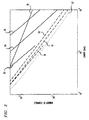
- FIG. 2 is plotted on the basis of system simulations and analytical calculations, and includes data for the Examples. All systems operate at a nominal system wavelength of 1550nm, with 50km amplifier spacings, and are somewhat conservative in setting span length as equal to the distance over which SNR degradation attains the value of 0.5dB. Receiver margin of 10dB and amplifier noise figure of 6dB are reasonably representative. Per-channel bit-rate is 10Gb/sec, WDM channel spacings are uniform at 0.5nm, and fiber insertion loss is 0.2dB/km. This results in an average launch power of a few mW per channel for a 5000km span (at 2.3dBm/channel). All values assumed are typical state-of-the-art values. Likely future improvements will further increase attainable span lengths and capacity.
- the effect of dispersion is to introduce a walk-off between pulses transmitted on different channels, thereby causing more bits to interact. Its effect is similar to an increase in a number of channels.
- the impact of the invention is most significant for dispersive systems since the effect of increasing dispersion is to decrease the fraction of SRS which is statistical (i.e. to decrease the non-deterministic fraction).
- Dispersion therefore, increases the fractional share of deterministic SRS which is amenable to shaping, with relative improvement in SRS-limited capacity.
- a dispersion of at least about 1.0ps/nm-km is assurance of sufficient improvement - ⁇ 3x - to justify use of the invention under most conditions.
- Fiber of dispersion of negative sign of the value of 1.0ps/nm-km or less has been specified for transoceanic systems - upgrading to WDM use is facilitated by the inventive procedures.
- preferred embodiments contemplate minimal dispersion values of 1.0ps/nm-km, or more desirably, 1.5ps/nm-km. Inclusion of substantial lengths of low-dispersion fiber does not, to first approximation, affect improvement realizable elsewhere in the system.
- transmission line of the minimal dispersion values for a distance totaling at least 1000km is considered to justify spectral shaping.
- FIG. 2 System representations on FIG. 2 are for the three types of fibers, both without and with shaping.
- Dash-line curves 30, 31 and 32 are for: DSF; finite dispersion fiber; and conventional fiber, respectively, without filtering.
- Corresponding shaped systems are shown as solid curves 33, 34 and 35.
- the solid curves assume filter placement independent of amplifiers - with filters placed at fiber intervals over which SRS depletion reaches 0.5dB. Since long lengths plotted correspond with relatively low power insertion (correspond with relatively small numbers of channels), the 40km-60km spacings found desirable for EDFAs correspond with depletion values at or below 0.5dB, filters may be expediently placed at amplifier sites. For relatively short lengths plotted, amplifier-to-amplifier depletion exceeds this value.
- curves 33, 34 and 35 may not be realistic.
- Curve 36 takes this into account and shows operational characteristics with the further requirement that filters not be closer than amplifiers.
- Curve 36 sets an upper-bound, on realizable SNR (of SRS origin) improvement independent of fiber dispersion.
- Curve 37 is included for comparison purposes, and shows the relationship for a "worst-case analysis" - in which phase correspondence of pulses is assured in all channels. (This condition is approached for a hypothetical fiber of channel-to-channel dispersion precisely at zero and with pulses in phase at insertion.)
- the data plotted on FIG. 3 is illustrative of a preferred embodiment in which the deterministic fraction of SRS depletion is at least 90% of the total SRS depletion.
- the figure shows the minimum number of channels required to reduce the statistical fluctuation of crosstalk sufficiently to meet this desire (to result in a ratio of 10% or less between the standard deviation and the average).
- Data is for: a fiber span of 50km; with fiber loss of 0.25dB/km; channel spacings equal to the product of 6.25 and per-channel bit-rate, for three bit-rates - 5Gb/sec, 10Gb/sec, 20Gb/sec (curves 40,41, 42, respectively).
- Soliton operation in accordance with the general view, is susceptible both to SRS degradation and to the inventive remedy.
- the essential nature of the soliton in requiring maintenance within specified power limits, may gain further advantage from the invention.
- the filter loss peak should be placed on the long wavelength side of the WDM channel set.
- the assumption is valid for designs in which standard arrangements have been made to eliminate irregularities in the spectrum and to assure flat output.
- the needed slope for correcting for SRS depletion is readily determined from the fiber depletion loss.
- the shaped amplifier output spectrum should have a slope corresponding with a highest-frequency channel gain which is larger than the lowest-frequency channel gain by the depletion loss for the fiber length to be compensated. Accordingly, for the 0.5dB-1.0dB spacing considered desirable for state-of-the-art fiber, slope should be 0.5dB-1.0dB, increasing in value in the direction of decreasing wavelength, as between the extreme channel wavelengths.
- Filter discussion has generally been in terms of the single individual element used for shaping an amplifier output from an initially flat spectrum. It may consist of two or more elements, again with the objective of altering an initially-flat amplification spectrum. While this approach is convenient, one or more combined elements may perform additional functions, e.g., as cancellation of perturbations. Another approach attenuates the channel separately and contemplates demultiplexing before filtering.
Landscapes
- Physics & Mathematics (AREA)
- Electromagnetism (AREA)
- Engineering & Computer Science (AREA)
- Computer Networks & Wireless Communication (AREA)
- Signal Processing (AREA)
- Optical Communication System (AREA)
- Optical Modulation, Optical Deflection, Nonlinear Optics, Optical Demodulation, Optical Logic Elements (AREA)
Claims (9)
- Optisches Wellenlängenmultiplex-Wellenleitersystem mit einem Sender (10) zum Einführen einer Menge modulierter WDM-Kanäle von Trägerwellenlängen, die zusammen ein WDM-Spektrum bei einer Systemwellenlänge bilden, einem Empfänger (11), einer faseroptischen Übertragungsleitung (12), die den Sender (10) und den Empfänger (11) verbindet, wobei die Leitung mindestens eine Spanne und mindestens einen optischen Verstärker (13) zum gleichzeitigen Verstärken aller WDM-Kanäle der Menge enthält, dadurch gekennzeichnet, daß das Produkt der Anzahl von Kanälen, der Bitrate pro Kanal und der Spannenlänge mindestens 320.000 km-Gb/s beträgt und das System weiterhin an mindestens einer Position in der Spanne ein Mittel zum Formen (14) des WDM-Spektrums, um einen verminderten Leistungspegel für einen Kanal langer Wellenlänge relativ zu einem Kanal kurzer Wellenlänge der Menge zu erhalten, enthält, wobei das Mittel im wesentlichen aus einem Filterelement besteht, wodurch die SRS-Verschlechterung verringert wird, um einen dem Produkt genügenden Betrieb zu ermöglichen.
- System nach Anspruch 1, bei dem die Spanne mehrere optische Verstärker (13) enthält.
- System nach Anspruch 2, bei dem das Mittel zum Formen (14) am Standort jedes Verstärkers (13) vorgesehen ist.
- System nach Anspruch 3, bei dem das Mittel zum Formen (14) ein Filterelement enthält, bei dem die Verstärkung der WDM-Kanäle wellenlängenveränderliche Steigung aufweist, wobei das Verstärkungsverhältnis für den Kanal der kürzesten Wellenlänge um einen Betrag, der den SRS-Verarmungsverlust am Verstärkerausgang approximiert, größer ist als für den Kanal der längsten Wellenlänge.
- System nach Anspruch 4, bei dem das Filterelement (14) gleichzeitig den Spektralteil des Verstärkerverstärkungsspektrums, der mit dem gesamten WDM-Spektrum korrespondiert, formt.
- System nach einem der vorhergehenden Ansprüche, bei dem die Spannenlänge mindestens 1000 km beträgt.
- System nach Anspruch 6, bei dem das Produkt der Anzahl von Kanälen und der Bitrate pro Kanal mindestens 100 Gb/s beträgt.
- System nach einem der vorhergehenden Ansprüche, bei dem die WDM-Menge mindestens 8 Kanäle enthält.
- System nach einem der vorhergehenden Ansprüche, bei dem im wesentlichen die gesamte Faser in der Spanne bei der Systemwellenlänge eine Dispersion von mindestens 1,0 ps/nm-km aufweist.
Applications Claiming Priority (2)
| Application Number | Priority Date | Filing Date | Title |
|---|---|---|---|
| US48924395A | 1995-06-12 | 1995-06-12 | |
| US489243 | 1995-06-12 |
Publications (3)
| Publication Number | Publication Date |
|---|---|
| EP0749224A2 EP0749224A2 (de) | 1996-12-18 |
| EP0749224A3 EP0749224A3 (de) | 1999-06-02 |
| EP0749224B1 true EP0749224B1 (de) | 2004-03-03 |
Family
ID=23943014
Family Applications (1)
| Application Number | Title | Priority Date | Filing Date |
|---|---|---|---|
| EP96304021A Expired - Lifetime EP0749224B1 (de) | 1995-06-12 | 1996-06-04 | Mehrkanaliges faseroptisches Nachrichtenübertragungssystem mit einem Filter zur Kompensation der Wellenlängenabhängigkeit des wegen stimulierter Raman-Streuung Übersprechverhaltens |
Country Status (5)
| Country | Link |
|---|---|
| US (1) | US5847862A (de) |
| EP (1) | EP0749224B1 (de) |
| JP (1) | JP3961587B2 (de) |
| CA (1) | CA2177874C (de) |
| DE (1) | DE69631717T2 (de) |
Families Citing this family (52)
| Publication number | Priority date | Publication date | Assignee | Title |
|---|---|---|---|---|
| US6052393A (en) | 1996-12-23 | 2000-04-18 | The Regents Of The University Of Michigan | Broadband Sagnac Raman amplifiers and cascade lasers |
| US6101368A (en) * | 1997-03-07 | 2000-08-08 | General Instrument Corporation | Bidirectional external device interface for communications receiver |
| US5892615A (en) * | 1997-03-17 | 1999-04-06 | Sdl, Inc. | Output power enhancement in optical fiber lasers |
| JPH1197779A (ja) * | 1997-09-22 | 1999-04-09 | Sony Corp | 多色光の変調増幅器及びこれを用いた投射型表示装置 |
| CN1081414C (zh) * | 1997-12-05 | 2002-03-20 | 清华大学 | 实现波分复用系统动态增益谱均衡的方法及其均衡放大器 |
| US6081368A (en) * | 1997-12-23 | 2000-06-27 | Lucent Technologies Inc. | Optical amplifier for bi-directional WDM optical communications systems |
| US6374006B1 (en) | 1998-03-20 | 2002-04-16 | Xtera Communications, Inc. | Chirped period gratings for raman amplification in circulator loop cavities |
| US6760148B2 (en) | 1998-03-24 | 2004-07-06 | Xtera Communications, Inc. | Nonlinear polarization amplifiers in nonzero dispersion shifted fiber |
| US6600592B2 (en) | 1998-03-24 | 2003-07-29 | Xtera Communications, Inc. | S+ band nonlinear polarization amplifiers |
| US6356384B1 (en) | 1998-03-24 | 2002-03-12 | Xtera Communications Inc. | Broadband amplifier and communication system |
| US6574037B2 (en) | 1998-06-16 | 2003-06-03 | Xtera Communications, Inc. | All band amplifier |
| US6335820B1 (en) | 1999-12-23 | 2002-01-01 | Xtera Communications, Inc. | Multi-stage optical amplifier and broadband communication system |
| US6359725B1 (en) | 1998-06-16 | 2002-03-19 | Xtera Communications, Inc. | Multi-stage optical amplifier and broadband communication system |
| US6885498B2 (en) | 1998-06-16 | 2005-04-26 | Xtera Communications, Inc. | Multi-stage optical amplifier and broadband communication system |
| DE69942932D1 (de) | 1998-06-16 | 2010-12-23 | Xtera Comm Inc | Dispersionskompensierendes und verstärkendes optisches element |
| US6567430B1 (en) | 1998-09-21 | 2003-05-20 | Xtera Communications, Inc. | Raman oscillator including an intracavity filter and amplifiers utilizing same |
| FR2790160B1 (fr) * | 1999-02-19 | 2001-05-04 | Cit Alcatel | Systeme de transmission regenere wdm |
| JP4763892B2 (ja) * | 1999-03-01 | 2011-08-31 | コーニンクレッカ フィリップス エレクトロニクス エヌ ヴィ | 情報信号のリアルタイムストリームをディスク状記録担体上に記憶する方法 |
| US7013088B1 (en) | 1999-05-26 | 2006-03-14 | Jds Uniphase Corporation | Method and apparatus for parallel optical interconnection of fiber optic transmitters, receivers and transceivers |
| JP3779502B2 (ja) * | 1999-08-12 | 2006-05-31 | 富士通株式会社 | 光増幅装置、光送信装置、光伝送システム、光増幅方法および光入射方法 |
| US7801444B1 (en) * | 1999-09-23 | 2010-09-21 | Alcatel | Amplification for optical fibre ultrawide band transmission systems |
| US6559988B1 (en) * | 1999-12-16 | 2003-05-06 | Lucent Technologies Inc. | Optical wavelength add/drop multiplexer for dual signal transmission rates |
| WO2001052372A1 (en) | 2000-01-12 | 2001-07-19 | Xtera Communications, Inc. | Raman amplifier with bi-directional pumping |
| AU2001264548A1 (en) | 2000-02-14 | 2001-10-23 | Xtera Communications, Inc. | Nonlinear optical loop mirror |
| JP3588435B2 (ja) | 2000-02-28 | 2004-11-10 | 富士通株式会社 | 光増幅装置、複合光増幅装置および光通信システム |
| US6384963B2 (en) * | 2000-03-03 | 2002-05-07 | Lucent Technologies Inc. | Optical communication system with co-propagating pump radiation for raman amplification |
| US6832023B1 (en) | 2000-05-19 | 2004-12-14 | Georgia Tech Research Corporation | Optical fiber gratings with azimuthal refractive index perturbation, method of fabrication, and devices for tuning, attenuating, switching, and modulating optical signals |
| JP2001345758A (ja) | 2000-05-31 | 2001-12-14 | Kddi Corp | 光伝送システム及び方法並びに光増幅伝送路 |
| JP4628523B2 (ja) | 2000-06-13 | 2011-02-09 | 富士通株式会社 | 光ファイバ伝送路の特性を評価するための方法、装置及びシステム |
| ATE405048T1 (de) * | 2000-07-03 | 2008-08-15 | Alcatel Lucent | Optisches übertagungssystem mit verminderung der ramaneffektserschöpfung |
| JP4671478B2 (ja) * | 2000-08-08 | 2011-04-20 | 富士通株式会社 | 波長多重光通信システムおよび波長多重光通信方法 |
| DE10040790B4 (de) * | 2000-08-21 | 2004-03-04 | Siemens Ag | Regelverfahren und optische Datenübertragungsstrecke mit einer Vorrichtung zur Kompensation von Änderungen des SRS-bedingten Leistungsaustausches |
| US6452715B1 (en) | 2000-08-29 | 2002-09-17 | Ciena Corporation | Method and apparatus for determining a fiber plant gain transfer function and utilizing same to control distributed gain |
| US6980747B1 (en) | 2000-11-28 | 2005-12-27 | Harris Corporation | Optically amplified receiver |
| US6560257B1 (en) | 2000-11-28 | 2003-05-06 | Harris Corporation | Low power laser driver |
| US6542277B2 (en) | 2000-12-11 | 2003-04-01 | Harris Corporation | Optically amplified back-up receiver |
| US6859622B1 (en) | 2000-12-26 | 2005-02-22 | Nortel Networks Limited | Predictive optimization of wavelength division multiplexed systems |
| US6456427B1 (en) * | 2001-01-03 | 2002-09-24 | Sycamore Networks, Inc. | Systems and methods for reducing a signal spectrum tilt |
| US6567580B2 (en) | 2001-02-01 | 2003-05-20 | Triquint Technology Holding Co. | Optical combiner system and method |
| US6748179B2 (en) | 2001-03-07 | 2004-06-08 | Harris Corporation | WDM channel monitoring system and method |
| US6587259B2 (en) | 2001-07-27 | 2003-07-01 | Xtera Communications, Inc. | System and method for controlling noise figure |
| US6614586B2 (en) * | 2001-07-30 | 2003-09-02 | Dorsal Networks, Inc. | Methods and systems for high performance, wide bandwidth optical communication systems using Raman amplification |
| US6819479B1 (en) | 2001-12-20 | 2004-11-16 | Xtera Communications, Inc. | Optical amplification using launched signal powers selected as a function of a noise figure |
| US20030133651A1 (en) * | 2002-01-16 | 2003-07-17 | Teraphase Technologies, Inc. | Filtering noise in optical signal transmission |
| KR100533600B1 (ko) * | 2003-03-12 | 2005-12-06 | 한국과학기술원 | 파장분할다중방식 메트로 광통신 장치 |
| US7565083B1 (en) * | 2004-06-22 | 2009-07-21 | Sprint Communications Company L.P. | Wavelength shifting in an optical network route to mitigate distortion in different types of fiber |
| DE102004058644A1 (de) * | 2004-12-02 | 2006-06-08 | Siemens Ag | Verfahren und Anordnung zur Kompensation des durch stimulierte Raman-Streuung verursachten bitmusterabhängigen Übersprechens |
| US7424229B2 (en) * | 2004-12-28 | 2008-09-09 | General Instrument Corporation | Methods and apparatus for Raman crosstalk reduction via idle data pattern control |
| US7271948B1 (en) * | 2006-12-19 | 2007-09-18 | General Instrument Corporation | Method and apparatus for reducing crosstalk and nonlinear distortions induced by raman interactions in a wavelength division mulitplexed (WDM) optical communication system |
| JP4774381B2 (ja) | 2007-03-16 | 2011-09-14 | 富士通株式会社 | 光受信装置およびその光レベル調整量設定方法 |
| US7920795B2 (en) * | 2007-04-05 | 2011-04-05 | General Instrument Corporation | Method and apparatus for transmitting multiple channels in a wavelength division multiplexed (WDM) optical communication system with reduced raman crosstalk and nonlinear distortions |
| US8320403B2 (en) | 2010-06-29 | 2012-11-27 | Excelitas Canada, Inc. | Multiplexed sensor array |
Family Cites Families (6)
| Publication number | Priority date | Publication date | Assignee | Title |
|---|---|---|---|---|
| US4261639A (en) * | 1979-11-13 | 1981-04-14 | Bell Telephone Laboratories, Incorporated | Optical pulse equalization in single-mode fibers |
| JPH0681119B2 (ja) * | 1986-04-17 | 1994-10-12 | 日本電気株式会社 | 波長多重光伝送方式 |
| US5225922A (en) * | 1991-11-21 | 1993-07-06 | At&T Bell Laboratories | Optical transmission system equalizer |
| US5587830A (en) * | 1993-05-28 | 1996-12-24 | Lucent Technologies Inc. | High capacity optical fiber network |
| US5327516A (en) * | 1993-05-28 | 1994-07-05 | At&T Bell Laboratories | Optical fiber for wavelength division multiplexing |
| US5365362A (en) * | 1993-09-10 | 1994-11-15 | At&T Bell Laboratories | Ultra-high capacity non-soliton optical transmission using optical phase conjugation |
-
1996
- 1996-05-31 CA CA002177874A patent/CA2177874C/en not_active Expired - Fee Related
- 1996-06-04 EP EP96304021A patent/EP0749224B1/de not_active Expired - Lifetime
- 1996-06-04 DE DE69631717T patent/DE69631717T2/de not_active Expired - Lifetime
- 1996-06-12 JP JP14965296A patent/JP3961587B2/ja not_active Expired - Fee Related
-
1997
- 1997-11-29 US US08/980,849 patent/US5847862A/en not_active Expired - Lifetime
Also Published As
| Publication number | Publication date |
|---|---|
| JPH098730A (ja) | 1997-01-10 |
| US5847862A (en) | 1998-12-08 |
| CA2177874A1 (en) | 1996-12-13 |
| CA2177874C (en) | 2000-06-20 |
| EP0749224A3 (de) | 1999-06-02 |
| DE69631717D1 (de) | 2004-04-08 |
| EP0749224A2 (de) | 1996-12-18 |
| JP3961587B2 (ja) | 2007-08-22 |
| DE69631717T2 (de) | 2005-02-24 |
Similar Documents
| Publication | Publication Date | Title |
|---|---|---|
| EP0749224B1 (de) | Mehrkanaliges faseroptisches Nachrichtenübertragungssystem mit einem Filter zur Kompensation der Wellenlängenabhängigkeit des wegen stimulierter Raman-Streuung Übersprechverhaltens | |
| CA2123145C (en) | High capacity optical fiber network | |
| KR100437750B1 (ko) | 광섬유통신시스템및방법 | |
| US5959750A (en) | Method of upgrading transmission capacity by Raman amplification | |
| US6021245A (en) | Method and optical transmission system for compensating dispersion in optical transmission paths | |
| US6567577B2 (en) | Method and apparatus for providing chromatic dispersion compensation in a wavelength division multiplexed optical transmission system | |
| US6782175B2 (en) | Dispersion map for slope compensating fibers | |
| JP4294153B2 (ja) | 波長多重光伝送システム | |
| US6317238B1 (en) | Chromatic dispersion management for optical wavelength division multiplexed transmission systems | |
| US6768872B1 (en) | Optical transmission system, optical transmission line and optical transmitter | |
| EP1170895B1 (de) | Optisches Übertagungssystem mit Verminderung der Ramaneffektserschöpfung | |
| HK1004730A (en) | Multi-channel optical fiber communication system | |
| Srivastava et al. | 32× 10 Gb/s WDM transmission over 640 km using broad band, gain-flattened erbium-doped silica fiber amplifiers | |
| US20020003647A1 (en) | Optical transmission system, its method, and optical amplification transmission line | |
| JP3396441B2 (ja) | 光中継装置および光通信システム | |
| US6577424B1 (en) | Chromatic dispersion compensator providing dispersion compensation to select channels of a wavelength division multiplexed signal | |
| US6462849B1 (en) | Optimizing launch points for dispersion-managed solitons | |
| AU728349B2 (en) | High capacity optical fiber network | |
| KR100488267B1 (ko) | 파장분할다중화광도파관시스템 | |
| Breuer et al. | Modeling of high-bit rate TDM and WDM systems | |
| JP2007049486A (ja) | 光伝送システム及びそのアップグレード方法 | |
| HK1004728B (en) | High capacity optical fiber network and fiber |
Legal Events
| Date | Code | Title | Description |
|---|---|---|---|
| PUAI | Public reference made under article 153(3) epc to a published international application that has entered the european phase |
Free format text: ORIGINAL CODE: 0009012 |
|
| AK | Designated contracting states |
Kind code of ref document: A2 Designated state(s): DE DK FR GB IT |
|
| RIN1 | Information on inventor provided before grant (corrected) |
Inventor name: TKACH, ROBERT WILLIAM Inventor name: FORGHIERI, FABRIZIO Inventor name: CHRAPLYVY, ANDREW R. |
|
| PUAL | Search report despatched |
Free format text: ORIGINAL CODE: 0009013 |
|
| 17P | Request for examination filed |
Effective date: 19990218 |
|
| AK | Designated contracting states |
Kind code of ref document: A3 Designated state(s): DE DK FR GB IT |
|
| 17Q | First examination report despatched |
Effective date: 20001031 |
|
| RTI1 | Title (correction) |
Free format text: MULTI-CHANNEL OPTICAL FIBER COMMUNICATION SYSTEM WITH FILTER TO COMPENSATE FOR STIMULATED-RAMAN-SCATTERING |
|
| GRAP | Despatch of communication of intention to grant a patent |
Free format text: ORIGINAL CODE: EPIDOSNIGR1 |
|
| GRAS | Grant fee paid |
Free format text: ORIGINAL CODE: EPIDOSNIGR3 |
|
| GRAA | (expected) grant |
Free format text: ORIGINAL CODE: 0009210 |
|
| AK | Designated contracting states |
Kind code of ref document: B1 Designated state(s): DE DK FR GB IT |
|
| REG | Reference to a national code |
Ref country code: GB Ref legal event code: FG4D |
|
| RTI1 | Title (correction) |
Free format text: MULTI-CHANNEL OPTICAL FIBER COMMUNICATION SYSTEM WITH FILTER TO COMPENSATE FOR WAVELENGTH DEPENDENCE OF CROSSTALK INDUCED |
|
| REF | Corresponds to: |
Ref document number: 69631717 Country of ref document: DE Date of ref document: 20040408 Kind code of ref document: P |
|
| PG25 | Lapsed in a contracting state [announced via postgrant information from national office to epo] |
Ref country code: DK Free format text: LAPSE BECAUSE OF FAILURE TO SUBMIT A TRANSLATION OF THE DESCRIPTION OR TO PAY THE FEE WITHIN THE PRESCRIBED TIME-LIMIT Effective date: 20040603 |
|
| ET | Fr: translation filed | ||
| PLBE | No opposition filed within time limit |
Free format text: ORIGINAL CODE: 0009261 |
|
| REG | Reference to a national code |
Ref country code: HK Ref legal event code: WD Ref document number: 1004730 Country of ref document: HK |
|
| STAA | Information on the status of an ep patent application or granted ep patent |
Free format text: STATUS: NO OPPOSITION FILED WITHIN TIME LIMIT |
|
| 26N | No opposition filed |
Effective date: 20041206 |
|
| PGFP | Annual fee paid to national office [announced via postgrant information from national office to epo] |
Ref country code: DE Payment date: 20130529 Year of fee payment: 18 Ref country code: GB Payment date: 20130529 Year of fee payment: 18 |
|
| PGFP | Annual fee paid to national office [announced via postgrant information from national office to epo] |
Ref country code: FR Payment date: 20130624 Year of fee payment: 18 Ref country code: IT Payment date: 20130619 Year of fee payment: 18 |
|
| REG | Reference to a national code |
Ref country code: DE Ref legal event code: R119 Ref document number: 69631717 Country of ref document: DE |
|
| GBPC | Gb: european patent ceased through non-payment of renewal fee |
Effective date: 20140604 |
|
| REG | Reference to a national code |
Ref country code: FR Ref legal event code: ST Effective date: 20150227 |
|
| PG25 | Lapsed in a contracting state [announced via postgrant information from national office to epo] |
Ref country code: IT Free format text: LAPSE BECAUSE OF NON-PAYMENT OF DUE FEES Effective date: 20140604 Ref country code: DE Free format text: LAPSE BECAUSE OF NON-PAYMENT OF DUE FEES Effective date: 20150101 |
|
| REG | Reference to a national code |
Ref country code: DE Ref legal event code: R119 Ref document number: 69631717 Country of ref document: DE Effective date: 20150101 |
|
| PG25 | Lapsed in a contracting state [announced via postgrant information from national office to epo] |
Ref country code: GB Free format text: LAPSE BECAUSE OF NON-PAYMENT OF DUE FEES Effective date: 20140604 Ref country code: FR Free format text: LAPSE BECAUSE OF NON-PAYMENT OF DUE FEES Effective date: 20140630 |