EP0749285B1 - Tomographie d'impedance electrique - Google Patents
Tomographie d'impedance electrique Download PDFInfo
- Publication number
- EP0749285B1 EP0749285B1 EP95910660A EP95910660A EP0749285B1 EP 0749285 B1 EP0749285 B1 EP 0749285B1 EP 95910660 A EP95910660 A EP 95910660A EP 95910660 A EP95910660 A EP 95910660A EP 0749285 B1 EP0749285 B1 EP 0749285B1
- Authority
- EP
- European Patent Office
- Prior art keywords
- electrodes
- wall
- reference ground
- electrical
- electrode
- Prior art date
- Legal status (The legal status is an assumption and is not a legal conclusion. Google has not performed a legal analysis and makes no representation as to the accuracy of the status listed.)
- Expired - Lifetime
Links
- 238000002593 electrical impedance tomography Methods 0.000 title description 22
- 239000000463 material Substances 0.000 claims description 51
- 238000000034 method Methods 0.000 claims description 26
- 238000012545 processing Methods 0.000 claims description 8
- 230000035945 sensitivity Effects 0.000 description 13
- 230000000694 effects Effects 0.000 description 8
- 150000001875 compounds Chemical class 0.000 description 7
- 239000004020 conductor Substances 0.000 description 7
- 238000012986 modification Methods 0.000 description 6
- 230000004048 modification Effects 0.000 description 6
- 238000005259 measurement Methods 0.000 description 5
- 239000011521 glass Substances 0.000 description 3
- 239000012212 insulator Substances 0.000 description 3
- 239000000203 mixture Substances 0.000 description 3
- 239000012811 non-conductive material Substances 0.000 description 3
- NIXOWILDQLNWCW-UHFFFAOYSA-N acrylic acid group Chemical group C(C=C)(=O)O NIXOWILDQLNWCW-UHFFFAOYSA-N 0.000 description 2
- 210000000038 chest Anatomy 0.000 description 2
- 230000005684 electric field Effects 0.000 description 2
- 230000005284 excitation Effects 0.000 description 2
- 238000002347 injection Methods 0.000 description 2
- 239000007924 injection Substances 0.000 description 2
- 238000011835 investigation Methods 0.000 description 2
- 239000007788 liquid Substances 0.000 description 2
- 230000002093 peripheral effect Effects 0.000 description 2
- XLYOFNOQVPJJNP-UHFFFAOYSA-N water Substances O XLYOFNOQVPJJNP-UHFFFAOYSA-N 0.000 description 2
- 238000003889 chemical engineering Methods 0.000 description 1
- 238000012790 confirmation Methods 0.000 description 1
- 238000013480 data collection Methods 0.000 description 1
- 230000007423 decrease Effects 0.000 description 1
- 238000007598 dipping method Methods 0.000 description 1
- 239000012777 electrically insulating material Substances 0.000 description 1
- 239000012530 fluid Substances 0.000 description 1
- 238000003384 imaging method Methods 0.000 description 1
- 238000000691 measurement method Methods 0.000 description 1
- 239000002184 metal Substances 0.000 description 1
- 239000007769 metal material Substances 0.000 description 1
- 238000010327 methods by industry Methods 0.000 description 1
- 239000004033 plastic Substances 0.000 description 1
- 229920003023 plastic Polymers 0.000 description 1
- 239000007787 solid Substances 0.000 description 1
- 239000000725 suspension Substances 0.000 description 1
- 239000008399 tap water Substances 0.000 description 1
- 235000020679 tap water Nutrition 0.000 description 1
- 210000000115 thoracic cavity Anatomy 0.000 description 1
Images


Classifications
-
- A—HUMAN NECESSITIES
- A61—MEDICAL OR VETERINARY SCIENCE; HYGIENE
- A61B—DIAGNOSIS; SURGERY; IDENTIFICATION
- A61B5/00—Measuring for diagnostic purposes; Identification of persons
- A61B5/05—Detecting, measuring or recording for diagnosis by means of electric currents or magnetic fields; Measuring using microwaves or radio waves
- A61B5/053—Measuring electrical impedance or conductance of a portion of the body
- A61B5/0536—Impedance imaging, e.g. by tomography
Definitions
- This invention relates to electrical impedance tomography (EIT), which has been known for some time in clinical applications and has recently gained acceptance as a useful technique for rapidly delineating the resistivity distribution of materials inside a process vessel or pipeline.
- EIT electrical impedance tomography
- EIT electronic medical image
- a set of electrodes spaced round, say, the thorax of a patient in electrical contact with the skin and to apply a constant current or constant voltage input electrical signal between each in turn of all the possible mutually adjacent pairs of electrodes. While the input signal is being applied to any one pair of mutually adjacent electrodes, the currents or voltages between each mutually adjacent pair of the remainder of the electrodes are measured and the resulting measured data are processed in known manner to yield, and display on a screen, a representation of the distribution of the electrical resistivity across a cross section of the patient which is bounded by the ring of electrodes.
- US Patent 5 272 624 It is also known from US Patent 5 272 624 to employ a medical electrical impedance imaging technique using set current patterns, in which electrical current is simultaneously injected to each of an array of spaced electrodes around the periphery of the body under investigation, the amplitude of the current varying according to, say, a cosinusoidal distribution around the periphery. The pattern of injected current is then successively altered around the electrode array, and the amplitude of the input signal is adapted to give the optimum distinguishability for the particular application of interest.
- the technique of US - 5 272 624 involves the measurement of the voltages developed at or near each electrode with respect to a common point, or earth reference. However, the currents are injected independently of this earth reference.
- EIT electrowetting-in-silicon
- vessels and pipelines made of electrically non-conductive material, such as acrylic or other plastics materials, in order to determine the resistivity distribution, over a cross-section of the vessel or pipeline, of its contents, notably when these are or may be a suspension of solids in a liquid of different resistivity, or a plurality of mutually immiscible liquids of different resistivities.
- the electrodes are mounted in and project through the vessel or pipeline wall so as to be directly in electrical contact with the contents within.
- a method of obtaining a representation of the distribution of electrical impedance within material contained within a containing wall comprising providing a plurality of mutually spaced electrodes mounted at spaced locations of the wall, electrically insulated from one another and arranged to be in electrical contact with material contained within the wall, applying between an electrical reference ground and each electrode, separately, an input electrical signal which, while applied to any one of the electrodes, causes respective output electrical signals to be generated between the reference ground and each other one of the electrodes, measuring the output electrical signals and processing the resulting measured data to provide a representation of the distribution, within the said material, of its electrical impedance.
- apparatus for obtaining a representation of the distribution of electrical impedance within a body of material comprising container means having a containing wall for containing the material, a plurality of electrodes mounted at spaced locations of the wall, electrically insulated from one another and arranged to be in electrical contact with material contained within the wall, means for generating, and applying between an electrical reference ground and each electrode, separately, an input signal which, while applied to any one of the electrodes, causes respective output electrical signals to be generated between the reference ground and each other one of the electrodes, means for measuring the output electrical signals, and means for processing the resulting measured data and providing a representation of the distribution, within the said material, of its electrical impedance.
- the wall itself is preferably made to serve as the reference ground relative to which the input and output electrical signals are applied and measured, preferably with the electrodes mounted in the wall but electrically insulated from it, and protruding through it into contact with the material contained within it.
- the reference ground is constituted, at any given moment, by all the electrodes, electrically strapped together, except for one of the electrodes to which an input signal is being applied relative to the reference ground, and one other of the electrodes at which an output electrical signal is being measured relative to the reference ground.
- the reference ground is provided by at least one electrode positioned within, and away from the boundary of, the material whose impedance distribution is to be reconstructed.
- This reference ground electrode may or may not be positioned at the centre of the vessel. If an electrically conductive component of the apparatus, such as a stirrer, is positioned within the vessel it may be made to serve as the reference ground electrode.
- the patient's skin constitutes the boundary of the material whose impedance distribution is to be reconstructed, and no other containing wall requires to be provided.
- the electrodes are applied to the skin in known manner and are not required to protrude through it.
- material 20 of which the resistivity distribution is to be determined is contained in a pipeline or other vessel having a circular wall 21 of acrylic or other electrically insulating material, and a plurality of electrodes 22 are mounted in the wall 21, equally spaced around it and each projecting through the wall so as to be in contact, inside the wall, with the material 20 and accessible, outside the wall, for attachment of an electrical connection.
- a source 23 of constant current is connected between one mutually adjacent pair of the electrodes 22, and a voltage measuring device 24 is connected between a mutually adjacent pair of the remaining electrodes 22 to measure the voltage existing between those electrodes in consequence of the current flowing between the pair of electrodes to which the source 23 is connected.
- the current source 23 would be maintained connected between the one pair of mutually adjacent electrodes while the voltages between each other mutually adjacent pair of the remaining electrodes is similarly measured.
- the current source 23 would then be connected between a different pair of mutually adjacent electrodes, while the resulting voltages between each mutually adjacent pair of the then remaining electrodes was measured, and the process would be repeated until the current source had been applied between each pair of mutually adjacent electrodes and, for each pair, the corresponding voltages between each mutually adjacent pair of the remaining electrodes had been measured. All the measured data would then be processed, in known manner, by computer means (not shown) to yield a representation of the distribution of electrical resistivity in the material 20.
- Figure 1 also shows, for the case where the material 20 is of uniform electrical resistivity, the system of equipotential lines 25 and current streamlines 26 which characterise the electrical field which is produced in the material 20 by applying an input electrical signal from the source 23 between one pair of mutually adjacent electrodes 22.
- the equipotential lines 25 fan out in such a way that elements of the wall 21 at different positions round its periphery are all at different potentials, and this would remain true even if the material 20 were not of uniform resistivity and there were in consequence a greater or lesser degree of perturbation of the symmetry and regularity of the illustrated pattern of equipotential lines and current streamlines.
- the type of field pattern illustrated in Figure 1 cannot obtain if the electrically insulating wall 20 is replaced by an electrically conductive wall, since, the greater its conductivity, the more closely will it approximate to an equipotential surface.
- the input and output electrical signals are applied or measured not between pairs of electrodes but, in each case, between an individual electrode and a common electrical reference ground.
- this conductive containing wall serves as the common electrical reference point, or ground.
- Each of the electrodes 22 mounted in the wall 21A, and numbered 1-16, respectively, is electrically insulated from the wall, for example by means of an insulating sleeve 27, as shown in Figure 3. It may be remarked, however, that the mounting of the electrodes in the wall 21A may in practice need to be more complicated than shown in Figure 3, since the material 20 within the wall 21A may be under substantial pressure which the electrodes and their mountings must be capable of resisting.
- an input electrical signal provided by the source 23 is applied between ground, i.e. the conductive wall 21A, and a single one of the electrodes 22 (that numbered 16, as illustrated) while output electrical signals are measured between each of the remaining electrodes 22 (numbered 1-15 respectively) and ground, by measuring means 24 as shown connected between ground and the electrode 22 numbered 10.
- Corresponding sets of output signals are measured while an input signal is applied to each other of the electrodes 22 individually, and the totality of measured data is then processed by the use of an appropriate algorithm to derive a representation of the resistivity distribution within the material 20.
- Figure 2 also shows, for the case of uniform resistivity of the material 20, the equipotential lines 25 and current streamlines 26 of the field pattern established in the material 20 by applying an input signal from the source 23 between ground (the wall 21A) and the electrode 22 which is numbered 16. It will be observed that the field pattern obtained in this case is quite different from that shown in Figure 1: in fact, the equipotential lines and current streamlines (which are always mutually orthogonal) have virtually interchanged with one another as between Figures 1 and 2.
- the input signal is an injected current (for example of 1.5 mA per cm peak-to-peak at a frequency of 9.6 kHz) applied to one electrode 22 and the output signals are the potentials of the other electrodes 22 relative to the wall 21A (from which, of course, they are insulated) those electrodes which are remote from that one to which the input signal is applied from the source 23 are relatively unaffected by the input signal, while the effect is progressively greater on those electrodes which are closer.
- Figure 4 shows typical voltages measured (in millivolts) at each of the electrodes numbered 1-15 when the input signal is applied to the electrode numbered 16, as shown in Figure 2.
- the voltage output signals thus obtained are substantially greater than would be measured between pairs of adjacent electrodes, with the same input signal applied between one such pair (as described with reference to Figure 1) but subject to the grounding or short-circuiting effect which is produced by an electrically conductive wall even though the electrodes are insulated from it.
- the sensitivity theorem for an electrically conducting body as originally developed by Geselowitz and later refined by Lehr, in essence enabled the impedance properties of a body to be determined from a 4-electrode (two-port) current excitation/ voltage measurement technique as illustrated in Figure 1.
- theorem was developed on the basis that the outer layer of the body was electrically non-conducting.
- the original four-lead two-port model is modified into an equivalent three-lead two-port model with, in the example shown in Figure 2, the conducting boundary wall 21A serving as the third lead.
- the Geselowitz/Lehr theorem is unchanged and the discretized area representing a two-dimensional cross-section of the vessel can be treated with Geselowitz's method to determine the sensitivity coefficient of each of the discretized regions.
- the circular cross-section of the vessel was divided into a set of 7,680 square pixels having a radius of 100 square pixels.
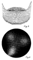
- the sensitivity coefficient S for each of these pixels was calculated using the Geselowitz method, and the reconstructed image composed of pixel grey-levels P x,y was formed, as proposed by Kotre, from the product of these coefficients with the logarithm of the ratio of measured voltages.
- each electrode 22 is connected to a respective 3-way switch 28 by which it can be connected to a common connector strap 29 to serve as part of a reference ground of the system, or to a connection 30 or to a connection 31.
- the signal source 23 is connected to apply input signals between the reference ground strap 29 and the connection 30 and any electrode 22 connected thereto, and the signal measuring means 24 is similarly connected to measure output signals generated between the strap 29 and the connection 31 and any electrode connected thereto.
- all the electrodes 22 are connected by their respective switches 28 to the strap 29 to form a reference ground of the system, except for one electrode 22 (that numbered 1 as shown in Figure 7) which is switched to receive an input signal applied by the source 23 between it and the reference ground, and one (that numbered 10 as shown in Figure 7) which is connected to the connection 31 to provide an output signal to the device 24.
- Each of the electrodes 22 is connected, separately, to the connection 29 for application to it of an input signal during an interval during which each other electrode, separately, is connected to the connection 31 for measurement of an output signal by the device 24.
- connection 29 for application to it of an input signal during an interval during which each other electrode, separately, is connected to the connection 31 for measurement of an output signal by the device 24.
- the arrangement shown in Figure 8 is generally similar to that described above with reference to Figure 7, but is provided, within the vessel containing the material 20, with a stirrer having an electrically conductive shaft 32 with paddle blades 33 which may be non-conductive.
- the stirrer shaft 32 serves as the reference ground and the signal source 23 and measuring device 24 are connected between the stirrer and, respectively, the connections 30 and 31.
- the strap 29 shown in Figure 7 may be omitted as shown, and any electrode 22 which is not connected by its switch 28 to the connection 30 or 31 is then left disconnected and floating.
- the algorithms used in processing the measured data obtained as described with reference to Figures 7 and 8, or in further variants described below will usually require appropriate modification to take account of the particular boundary conditions set up by the electrode connections.
- Use of a reference ground electrode at or near the centre of the vessel as shown in Figure 8 is effective to increase the sensitivity of the system near the centre of the vessel where, otherwise, it is low compared with the sensitivity near the peripheral boundary.
- a stirrer or other electrode as shown in Figure 8 is provided within the material 20 in an arrangement which is otherwise as shown in Figure 7, it may also be provided, like each peripheral electrode 22, with switch means to connect it either to the reference ground connection 29 or via the connections 30 and 31 to either the input signal source 23 or the output signal measuring means 24.
- switch means to connect it either to the reference ground connection 29 or via the connections 30 and 31 to either the input signal source 23 or the output signal measuring means 24.
- an inner electrode at which an input signal may be applied or an output signal may be measured, or which may serve as the, or part of the, signal reference ground such an inner electrode may similarly be employed when single-electrode excitation and measurement in accordance with the invention are employed in clinical practice.
- an inner electrode at the free end of an insulated cable may be passed down the oesophagus to the required level within the thorax (as has indeed already been proposed in the case of conventional EIT using two-electrode signal input and two-electrode output signal measurement).
- the provision of an electrically conductive boundary round the body of material which is to be investigated has the effect of interchanging the pattern of equipotential lines and current streamlines in the body, as compared with the case where the boundary is non-conductive.
- the electrodes to be applied to a patient may be mounted in insulated manner in a band or belt of electrically conductive (and preferably elastic) material which can then be fitted round the part of the patient which is to be investigated.
- the belt may be of non-conductive material, but fitted with compound electrodes such as those suggested in a paper: "Using Compound Electrodes in EIT" (Ping Hua et al , IEEE Trans.
- a compound electrode comprises a small inner electrode surrounded by an outer electrode of much larger surface area, the intention being that an input current signal can be applied between the outer electrodes of two compound electrodes while an output voltage signal is measured between the inner electrodes of the same or a different pair of compound electrodes.
- a belt of such compound electrodes may also, however, be used in carrying out EIT in accordance with the present invention if it is fitted to a patient and all its outer electrodes are strapped together as an effective conductive outer boundary and as a signal reference ground, while input and output signals, relative to the reference ground, are applied to or measured at individual inner electrodes of the compound electrodes
Landscapes
- Health & Medical Sciences (AREA)
- Life Sciences & Earth Sciences (AREA)
- Nuclear Medicine, Radiotherapy & Molecular Imaging (AREA)
- Biomedical Technology (AREA)
- Medical Informatics (AREA)
- Biophysics (AREA)
- Pathology (AREA)
- Engineering & Computer Science (AREA)
- Radiology & Medical Imaging (AREA)
- Heart & Thoracic Surgery (AREA)
- Physics & Mathematics (AREA)
- Molecular Biology (AREA)
- Surgery (AREA)
- Animal Behavior & Ethology (AREA)
- General Health & Medical Sciences (AREA)
- Public Health (AREA)
- Veterinary Medicine (AREA)
- Investigating Or Analyzing Materials By The Use Of Electric Means (AREA)
- Measurement And Recording Of Electrical Phenomena And Electrical Characteristics Of The Living Body (AREA)
Claims (19)
- Procédé d'obtention d'une représentation de la distribution de l'impédance électrique dans un matériau contenu dans une paroi extérieure, consistant à fournir une pluralité d'électrodes mutuellement espacées, montées à des emplacements espacés de la paroi, électriquement isolées les unes des autres et agencées pour être en contact électrique avec le matériau contenu dans la paroi, appliquer entre une masse électrique de référence et chaque électrode, de manière séparée, un signal électrique d'entrée qui, alors qu'il est appliqué à l'une quelconque des électrodes, amène des signaux électriques de sortie respectifs à être générés entre la masse de référence et chaque autre électrode des électrodes, mesurer les signaux électriques de sortie et traiter les données mesurées résultantes pour fournir une représentation de la distribution, dans ledit matériau, de son impédance électrique.
- Procédé selon la revendication 1, dans lequel le signal électrique d'entrée est appliqué en séquence entre la masse électrique de référence et chaque électrode.
- Procédé selon la revendication 1, dans lequel la paroi extérieure étant électriquement conductrice, elle est utilisée en tant que masse électrique de référence par rapport à laquelle les signaux électriques d'entrée et de sortie sont appliqués et mesures.
- Procédé selon la revendication 1, dans lequel la paroi extérieure étant électriquement non-conductrice, ladite masse de référence est formée en reliant mutuellement, à un moment quelconque, toutes les électrodes excepté les deux électrodes auxquelles respectivement un signal d'entrée est appliqué et un signal de sortie est mesuré.
- Procédé selon la revendication 1, et comportant l'étape consistant à fournir, en tant que masse de référence, une électrode située dans ledit matériau et espacée de la limite de celui-ci.
- Procédé selon la revendication 1, en utilisation clinique, dans lequel ladite paroi limite est la peau d'un patient et les électrodes sont appliquées en contact avec la peau.
- Procédé selon la revendication 6, dans lequel les électrodes sont agencées sur une courroie et la courroie est agencée autour d'une partie du patient.
- Procédé selon la revendication 7, dans lequel la courroie étant électriquement conductrice et électriquement isolée des électrodes, elle est utilisée en tant que masse de référence.
- Dispositif pour obtenir une représentation de la distribution de l'impédance électrique dans un corps de matériau (20) comportant des moyens formant conteneur ayant une paroi extérieure (21) pour contenir le matériau, une pluralité d'électrodes (22) montées à des emplacements espacés de la paroi (21), électriquement isolées les unes des autres et agencées pour être en contact électrique avec le matériau contenu dans la paroi, des moyens pour générer, et appliquer entre une masse électrique de référence (21A, 32) et chaque électrode, de manière séparée, un signal d'entrée qui, alors qu'il est appliqué à une quelconque des électrodes (22) amène des signaux électriques de sortie respectifs à être générés entre la masse de référence (21A, 32) et chaque autre électrode des électrodes (22), des moyens (34) pour mesurer les signaux électriques de sortie, et des moyens pour traiter les données mesurées résultantes et fournir une représentation de la distribution, dans ledit matériau, de son impédance électrique.
- Dispositif selon la revendication 9, dans lequel lesdits moyens pour générer comportent de plus des moyens pour appliquer en séquence ledit signal d'entrée entre la masse électrique de référence et chaque électrode.
- Dispositif selon la revendication 9, dans lequel lesdites électrodes sont montées dans la paroi et font saillie à travers celle-ci pour être en contact électrique avec le matériau contenu dans la paroi.
- Dispositif selon la revendication 11, dans lequel la paroi est électriquement conductrice et les électrodes montées dans celle-ci sont électriquement isolées de celle-ci.
- Dispositif selon la revendication 9, dans lequel la paroi extérieure est électriquement conductrice et constitue ladite masse électrique de référence par rapport à laquelle les signaux électriques d'entrée et de sortie sont appliqués et mesures.
- Dispositif selon la revendication 9, dans lequel la paroi extérieure est électriquement non-conductrice et, pour constituer ladite masse de référence, des moyens de commutation sont fournis pour connecter mutuellement, à un moment quelconque, toutes les électrodes à l'exception des deux électrodes au niveau desquelles respectivement un signal d'entrée est appliqué et un signal de sortie est mesuré.
- Dispositif selon la revendication 9, et comportant, en tant que masse de référence, une électrode située dans ledit matériau et espacée de la limite de celui-ci.
- Dispositif selon la revendication 15, dans lequel la masse de référence est constituée par des moyens, tel qu'un agitateur, qui servent aussi à un autre but.
- Dispositif selon la revendication 9, en utilisation clinique, dans lequel la peau d'un patient constitue la paroi limite et les électrodes sont appliquées en contact avec la peau.
- Dispositif selon la revendication 17, dans lequel les électrodes sont agencées sur une courroie et la courroie est agencée autour d'une partie du patient.
- Dispositif selon la revendication 18, dans lequel la courroie est électriquement conductrice et électriquement isolée des électrodes et constitue ladite masse de référence.
Applications Claiming Priority (7)
| Application Number | Priority Date | Filing Date | Title |
|---|---|---|---|
| GB9404766A GB9404766D0 (en) | 1994-03-11 | 1994-03-11 | Electrical resistance tomography |
| GB9404766 | 1994-03-11 | ||
| GB9405794 | 1994-03-23 | ||
| GB9405794A GB9405794D0 (en) | 1994-03-23 | 1994-03-23 | Electrical impedance tomography |
| GB9424129A GB9424129D0 (en) | 1994-03-11 | 1994-11-25 | Electrical impedance tomography |
| GB9424129 | 1994-11-25 | ||
| PCT/GB1995/000520 WO1995024155A1 (fr) | 1994-03-11 | 1995-03-10 | Tomographie d'impedance electrique |
Publications (2)
| Publication Number | Publication Date |
|---|---|
| EP0749285A1 EP0749285A1 (fr) | 1996-12-27 |
| EP0749285B1 true EP0749285B1 (fr) | 1998-11-04 |
Family
ID=27267094
Family Applications (1)
| Application Number | Title | Priority Date | Filing Date |
|---|---|---|---|
| EP95910660A Expired - Lifetime EP0749285B1 (fr) | 1994-03-11 | 1995-03-10 | Tomographie d'impedance electrique |
Country Status (6)
| Country | Link |
|---|---|
| US (1) | US5807251A (fr) |
| EP (1) | EP0749285B1 (fr) |
| JP (1) | JP3759606B2 (fr) |
| AU (1) | AU699170B2 (fr) |
| DE (1) | DE69505799T2 (fr) |
| WO (1) | WO1995024155A1 (fr) |
Families Citing this family (74)
| Publication number | Priority date | Publication date | Assignee | Title |
|---|---|---|---|---|
| JPH0647224B2 (ja) * | 1987-08-11 | 1994-06-22 | アミテック株式会社 | 矩形枠体用研削装置 |
| GB9522060D0 (en) * | 1995-10-27 | 1996-01-03 | Williams Richard A | Characterisation of flowing dispersions |
| CA2191285A1 (fr) * | 1996-11-26 | 1998-05-26 | Philip Maurice Church | Electrode pour systeme de tomographie commande par l'impedance electrique |
| JP3125730B2 (ja) * | 1997-09-11 | 2001-01-22 | 憲一 山越 | 血行動態表示装置 |
| CA2217603C (fr) * | 1997-10-02 | 2003-12-23 | Tasc Ltd. | Systeme et methodes de visualisation d'un objet au moyen de son impedance |
| US6745070B2 (en) | 1997-10-03 | 2004-06-01 | Tasc Ltd. | High definition electrical impedance tomography |
| WO1999052588A1 (fr) * | 1998-04-14 | 1999-10-21 | Koninklijke Philips Electronics N.V. | Appareil d'electrostimulation |
| US6122544A (en) * | 1998-05-01 | 2000-09-19 | Organ; Leslie William | Electrical impedance method and apparatus for detecting and diagnosing diseases |
| AUPQ113799A0 (en) * | 1999-06-22 | 1999-07-15 | University Of Queensland, The | A method and device for measuring lymphoedema |
| US6594521B2 (en) | 1999-12-17 | 2003-07-15 | Electrical Geodesics, Inc. | Method for localizing electrical activity in the body |
| US7499745B2 (en) * | 2000-02-28 | 2009-03-03 | Barbara Ann Karmanos Cancer Institute | Multidimensional bioelectrical tissue analyzer |
| US6768921B2 (en) * | 2000-12-28 | 2004-07-27 | Z-Tech (Canada) Inc. | Electrical impedance method and apparatus for detecting and diagnosing diseases |
| EP1347706B1 (fr) | 2000-12-30 | 2008-05-21 | The University Of Leeds | Tomographie d'impedance electrique |
| US6529759B1 (en) | 2001-03-08 | 2003-03-04 | Electrical Geodesics, Inc. | Method for mapping internal body tissue |
| US7840250B2 (en) | 2001-11-13 | 2010-11-23 | Electrical Geodesics, Inc. | Method for neural current imaging |
| US20080064981A1 (en) * | 2002-11-07 | 2008-03-13 | Christopher Gregory | Method and apparatus for determining electrical properties of objects containing inhomogeneities |
| DE10315863B4 (de) * | 2003-04-08 | 2013-03-14 | Dräger Medical GmbH | Elektrodengürtel |
| US20040236202A1 (en) * | 2003-05-22 | 2004-11-25 | Burton Steven Angell | Expandable strap for use in electrical impedance tomography |
| US20050107833A1 (en) | 2003-11-13 | 2005-05-19 | Freeman Gary A. | Multi-path transthoracic defibrillation and cardioversion |
| US20080076998A1 (en) * | 2003-12-01 | 2008-03-27 | Z-Tech (Canada) Inc. | Breast electrode array and method of analysis for detecting and diagnosing diseases |
| WO2005065090A2 (fr) * | 2003-12-30 | 2005-07-21 | The Mitre Corporation | Techniques de tomographie electrostatique a l'echelle d'un batiment |
| KR100598146B1 (ko) * | 2004-04-28 | 2006-07-07 | 메디게이트(주) | 체임피던스 측정용 벨트 전극 장치 |
| JP4848369B2 (ja) | 2004-06-18 | 2011-12-28 | インぺディメッド リミテッド | 浮腫検出のための装置と該動作方法 |
| US8103337B2 (en) | 2004-11-26 | 2012-01-24 | Impedimed Limited | Weighted gradient method and system for diagnosing disease |
| CA2609111C (fr) | 2005-07-01 | 2016-10-18 | Scott Chetham | Procede et appareil d'execution de mesures d'impedance en fonction de ladetermination d'une disposition d'electrode au moyen d'une representation affichee |
| CA2608962C (fr) | 2005-07-01 | 2016-12-06 | Scott Chetham | Systeme de surveillance |
| EP1912563B1 (fr) | 2005-08-02 | 2016-04-20 | Impedimed Limited | Valeurs de parametres d'impedance |
| GB0516158D0 (en) * | 2005-08-05 | 2005-09-14 | Univ Montfort | An apparatus and method for `non-contact' electrical impedance imaging |
| US20100292603A1 (en) * | 2005-09-21 | 2010-11-18 | Beth Israel Deaconess Medical Center, Inc. | Electrical Impedance Myography |
| WO2007041783A1 (fr) | 2005-10-11 | 2007-04-19 | Impedance Cardiology Systems, Inc. | Surveillance de l'etat d'hydratation |
| EP1813345A1 (fr) * | 2006-01-30 | 2007-08-01 | Sulzer Pumpen Ag | Procédé et appareil pour contrôler l'efficacité du mixage |
| ES2545730T3 (es) * | 2006-05-30 | 2015-09-15 | Impedimed Limited | Mediciones de impedancia |
| EP2091425A4 (fr) | 2006-11-30 | 2012-07-25 | Impedimed Ltd | Appareil de mesure |
| EP2106241B1 (fr) | 2007-01-15 | 2015-05-06 | Impedimed Limited | Procédé pour effectuer des mesures d'impédance sur un sujet |
| JP5101685B2 (ja) | 2007-03-30 | 2012-12-19 | インぺディメッド リミテッド | 補償レベルを可変制御して抵抗性信号および容量性信号の負荷を低減するための動作保護回路 |
| JP5419861B2 (ja) * | 2007-04-20 | 2014-02-19 | インぺディメッド リミテッド | インピーダンス測定装置および方法 |
| US20110046505A1 (en) * | 2007-08-09 | 2011-02-24 | Impedimed Limited | Impedance measurement process |
| ES2615128T3 (es) | 2007-11-05 | 2017-06-05 | Impedimed Limited | Determinación de impedancia |
| AU2008207672B2 (en) | 2008-02-15 | 2013-10-31 | Impedimed Limited | Impedance Analysis |
| EP2348987B1 (fr) | 2008-11-28 | 2017-03-22 | Impedimed Limited | Procédé de mesure d'impédance |
| KR20110108387A (ko) * | 2009-01-27 | 2011-10-05 | 싸이베이스 에이비 | 임피던스의 다중 전극 측정을 위한 스위치 프로브 |
| US9615767B2 (en) | 2009-10-26 | 2017-04-11 | Impedimed Limited | Fluid level indicator determination |
| US9585593B2 (en) | 2009-11-18 | 2017-03-07 | Chung Shing Fan | Signal distribution for patient-electrode measurements |
| US8264246B2 (en) * | 2010-01-05 | 2012-09-11 | General Electric Company | Electrical network representation of a distributed system |
| US8054094B1 (en) * | 2010-06-10 | 2011-11-08 | General Electric Company | Image reconstruction based constrained maximization |
| JP5656219B2 (ja) * | 2010-12-16 | 2015-01-21 | 一般財団法人電力中央研究所 | インピーダンス計測センサおよびインピーダンス計測装置 |
| JP5704326B2 (ja) * | 2011-03-28 | 2015-04-22 | 株式会社Ihi | トモグラフィ装置及びトモグラフィ計測方法 |
| DE102011018505B4 (de) * | 2011-04-23 | 2021-06-24 | Drägerwerk AG & Co. KGaA | Vorrichtung zur Elektroimpedanztomographie |
| DE102011108252A1 (de) * | 2011-07-22 | 2013-01-24 | Rheinisch-Westfälische Technische Hochschule Aachen | Verfahren und Vorrichtung zur Überwachung des Harnblasenfüllstandes eines Patienten |
| US8983578B2 (en) | 2012-02-27 | 2015-03-17 | General Electric Company | System and method for transducer placement in soft-field tomography |
| EP2944253A4 (fr) | 2013-01-09 | 2016-08-24 | Timpel Sa | Procédé et appareil pour l'acquisition de signaux pour tomographie par impédance électrique |
| CA2897144C (fr) | 2013-02-01 | 2020-07-28 | Arto Voutilainen | Procede et appareil permettant de determiner l'emplacement d'une interface d'interet et programme informatique |
| CN105308445B (zh) * | 2013-03-07 | 2019-04-05 | 诺克索莱有限公司 | 用于调查目标域中的介电常数的方法和装置 |
| JP2014202722A (ja) * | 2013-04-10 | 2014-10-27 | 株式会社豊田中央研究所 | 混相状態分布計測装置 |
| JP6423183B2 (ja) * | 2014-06-25 | 2018-11-14 | 株式会社Ihi | トモグラフィ計測方法 |
| DE102014009439B4 (de) | 2014-06-25 | 2018-05-30 | Drägerwerk AG & Co. KGaA | Vorrichtung und Verfahren zur Verarbeitung von tomografischen Daten |
| GB201416287D0 (en) * | 2014-09-15 | 2014-10-29 | Univ Leeds | Tomography apparatus, multi-phase flow monitoring system and corresponding methods |
| GB201416280D0 (en) | 2014-09-15 | 2014-10-29 | Univ Leeds | Tomography apparatus and method |
| FR3029287B1 (fr) | 2014-11-28 | 2016-12-30 | Commissariat Energie Atomique | Methode d'imagerie d'un milieu par mesures electriques avec correction d'impedance de contact |
| DE102014018107B4 (de) | 2014-12-09 | 2022-03-10 | Drägerwerk AG & Co. KGaA | Vorrichtung zur Verarbeitung von tomografischen Daten zur Darstellung eines Therapieverlaufs |
| DE102014018490A1 (de) | 2014-12-16 | 2015-11-05 | Drägerwerk AG & Co. KGaA | Vorrichtung und Verfahren zur Entfernung impulsartiger Störsignale aus Misssignalen eines für eine Bildgebung der Lunge geeignetes Elektro-Impedanz-Tomographie-Gerätes |
| US10874324B2 (en) * | 2015-10-20 | 2020-12-29 | General Electric Company | Detection of physiological changes in impedance monitoring |
| DE102016011161A1 (de) | 2016-09-16 | 2018-03-22 | Drägerwerk AG & Co. KGaA | Vorrichtung zur Verarbeitung und Visualisierung von Daten eines Elektro-lmpedanz-Tomographie-Gerätes zu einer Ermittlung und Visualisierung von regionalen Eigenschaften der Ventilation der Lunge |
| DE102016014251B4 (de) | 2016-11-30 | 2023-02-02 | Drägerwerk AG & Co. KGaA | Vorrichtung und Verfahren zur Ermittlung einer axialen Position einer Elektrodenanordnung zur Elektro-Impedanz-Tomographie |
| DE102016014252B4 (de) | 2016-11-30 | 2023-02-02 | Drägerwerk AG & Co. KGaA | Vorrichtung und Verfahren zur Bestimmung einer Umfangsform einer Elektrodenanordnung zur Elektro-Impedanz-Tomographie |
| DE102017006107A1 (de) | 2017-06-28 | 2019-01-03 | Drägerwerk AG & Co. KGaA | Vorrichtung und Verfahren zur Verarbeitung und Visualisierung von mittels eines Elektro-lmpedanz-Tomographie-Gerätes (EIT) gewonnenen Daten hinsichtlich eines Durchblutungszustandes von Herz und Lunge |
| DE102017007224A1 (de) | 2017-08-02 | 2019-02-07 | Drägerwerk AG & Co. KGaA | Vorrichtung und Verfahren zu einer Bestimmung von Differenzkennzahlen auf Basis von EIT-Daten |
| US11412946B2 (en) | 2017-11-14 | 2022-08-16 | Timpel Medical B.V. | Electrical impedance tomography device and system having a multi-dimensional electrode arrangement |
| US12228535B2 (en) | 2018-04-25 | 2025-02-18 | Spectrohm, Inc. | Methods for determining regional impedance characteristics of inhomogenous specimens using guided electromagnetic fields |
| US10542906B2 (en) | 2018-04-25 | 2020-01-28 | Spectrohm, Inc. | Tomographic systems and methods for determining characteristics of inhomogenous specimens using guided electromagnetic fields |
| JP2020046182A (ja) * | 2018-09-14 | 2020-03-26 | 日置電機株式会社 | 処理装置および処理方法 |
| DE102018008545A1 (de) | 2018-11-01 | 2020-05-07 | Drägerwerk AG & Co. KGaA | Vorrichtung und Verfahren zur Elektro-lmpedanz-Tomographie (EIT) mit Ermittlung einer Herzregion |
| CN111024772B (zh) * | 2019-12-03 | 2022-06-14 | 西安科技大学 | 激光熔覆熔池微电阻分布成像方法与装置 |
| DE102021134348A1 (de) | 2021-12-22 | 2023-06-22 | Drägerwerk AG & Co. KGaA | Verfahren und System mit einer Messvorrichtung und einer Analysevorrichtung zu einer Verarbeitung von Daten |
Family Cites Families (21)
| Publication number | Priority date | Publication date | Assignee | Title |
|---|---|---|---|---|
| DE2813068A1 (de) * | 1978-03-25 | 1979-10-04 | Philips Patentverwaltung | Verfahren und vorrichtung zur ermittlung von inneren koerperstrukturen |
| FR2486386A1 (fr) * | 1980-07-09 | 1982-01-15 | Argamakoff Alexis | Detecteur combine thermographique et impedancemetrique pour la detection precoce de tumeurs |
| US4709704A (en) * | 1984-03-06 | 1987-12-01 | The Kendall Company | Monitoring device for bio-signals |
| US4920490A (en) * | 1988-01-28 | 1990-04-24 | Rensselaer Polytechnic Institute | Process and apparatus for distinguishing conductivities by electric current computed tomography |
| US5184624A (en) * | 1988-04-15 | 1993-02-09 | The University Of Sheffield | Electrical impedance tomography |
| US4974598A (en) * | 1988-04-22 | 1990-12-04 | Heart Map, Inc. | EKG system and method using statistical analysis of heartbeats and topographic mapping of body surface potentials |
| US5020541A (en) * | 1988-07-13 | 1991-06-04 | Physio-Control Corporation | Apparatus for sensing lead and transthoracic impedances |
| GB9013177D0 (en) * | 1990-06-13 | 1990-08-01 | Brown Brian H | Real-time imaging, etc. |
| US5272624A (en) * | 1990-10-02 | 1993-12-21 | Rensselaer Polytechnic Institute | Current patterns for impedance tomography |
| SE466987B (sv) * | 1990-10-18 | 1992-05-11 | Stiftelsen Ct Foer Dentaltekni | Anordning foer djupselektiv icke-invasiv, lokal maetning av elektrisk impedans i organiska och biologiska material samt prob foer maetning av elektrisk impedans |
| GB9113830D0 (en) * | 1991-06-27 | 1991-08-14 | Brown Brian H | Applied potential tomography |
| US5381333A (en) * | 1991-07-23 | 1995-01-10 | Rensselaer Polytechnic Institute | Current patterns for electrical impedance tomography |
| US5284142A (en) * | 1991-12-16 | 1994-02-08 | Rensselaer Polytechnic Institute | Three-dimensional impedance imaging processes |
| US5544662A (en) * | 1991-07-09 | 1996-08-13 | Rensselaer Polytechnic Institute | High-speed electric tomography |
| US5390110A (en) * | 1991-07-09 | 1995-02-14 | Rensselaer Polytechnic Institute | Layer stripping process for impedance imaging |
| GB9116215D0 (en) * | 1991-07-26 | 1991-09-11 | Nat Res Dev | Electrical impedance tomography |
| US5351697A (en) * | 1991-12-16 | 1994-10-04 | Rensseleaer Polytechnic Institute | Three-dimensional impedance imaging process |
| GB9226376D0 (en) * | 1992-12-18 | 1993-02-10 | British Tech Group | Tomography |
| DE4243628A1 (de) * | 1992-12-22 | 1994-06-23 | Siemens Ag | Vorrichtung zur nichtinvasiven Bestimmung der räumlichen Verteilung der elektrischen Impedanz im Innern eines Lebewesens |
| US5560372A (en) * | 1994-02-02 | 1996-10-01 | Cory; Philip C. | Non-invasive, peripheral nerve mapping device and method of use |
| US5657552A (en) * | 1995-11-09 | 1997-08-19 | Reineck; Rollin | Device for measuring distances on globes or maps |
-
1995
- 1995-03-10 JP JP52331895A patent/JP3759606B2/ja not_active Expired - Fee Related
- 1995-03-10 WO PCT/GB1995/000520 patent/WO1995024155A1/fr not_active Ceased
- 1995-03-10 EP EP95910660A patent/EP0749285B1/fr not_active Expired - Lifetime
- 1995-03-10 AU AU18570/95A patent/AU699170B2/en not_active Ceased
- 1995-03-10 US US08/700,370 patent/US5807251A/en not_active Expired - Lifetime
- 1995-03-10 DE DE69505799T patent/DE69505799T2/de not_active Expired - Lifetime
Also Published As
| Publication number | Publication date |
|---|---|
| DE69505799T2 (de) | 1999-04-22 |
| WO1995024155A1 (fr) | 1995-09-14 |
| JP3759606B2 (ja) | 2006-03-29 |
| JPH09510014A (ja) | 1997-10-07 |
| DE69505799D1 (de) | 1998-12-10 |
| AU1857095A (en) | 1995-09-25 |
| US5807251A (en) | 1998-09-15 |
| AU699170B2 (en) | 1998-11-26 |
| EP0749285A1 (fr) | 1996-12-27 |
Similar Documents
| Publication | Publication Date | Title |
|---|---|---|
| EP0749285B1 (fr) | Tomographie d'impedance electrique | |
| Gisser et al. | Theory and performance of an adaptive current tomography system | |
| CA1196691A (fr) | Systeme et methodes de reconstruction pour imagerie a impedance | |
| Griffiths | Magnetic induction tomography | |
| US4291708A (en) | Apparatus and method for detection of tumors in tissue | |
| US11598739B2 (en) | Methods and systems for high fidelity electrical tomographic processes | |
| DE10136529C1 (de) | Kombinierter elektrischer Impedanz- und Ultraschall-Scanner | |
| JPH0649032B2 (ja) | Nmrイメ−ジング装置に用いるカテ−テル | |
| US20040201380A1 (en) | Method and apparatus for rapid tomographic measurements of the electrical conductivity distribution of a sample | |
| EP0314088B1 (fr) | Dispositif de mesure de conductivité | |
| Griffiths et al. | A dual-frequency applied potential tomography technique: computer simulations | |
| Sel et al. | Finite-element modeling of needle electrodes in tissue from the perspective of frequent model computation | |
| US20210219863A1 (en) | Electrical Impedance Measurement and EIT Image for Location of a Micro Bio-Channel Under Skin | |
| US20030023185A1 (en) | Measurement system for examining a section of tissue on a patient and the use of a measurement system of this type | |
| Wang et al. | Four-dimensional ultrasound current source density imaging of a dipole field | |
| Jossinet et al. | Electrical impedance endo-tomography: imaging tissue from inside | |
| del Castillo et al. | On increasing the velocity of a nerve impulse | |
| EP3651641B1 (fr) | Système de mesure de l'impédance électrique dans des tissus humains | |
| JP3109065B2 (ja) | 誘電緩和測定用電極 | |
| Yankielun et al. | Development of an instrument to electronically measure, record, and image washover of a towed body | |
| Wort et al. | Preliminary assessment of electrical impedance tomography technology to detect minelike objects | |
| Nolte et al. | An Automated System for Frequency-Differential Data Collection in EIT | |
| Ridzuan Aw et al. | Development of Electrical Resistance Tomography Applying Vertical Metallic Column | |
| West et al. | Application-specific optimization of regularization for electrical impedance tomography | |
| Kotre | Detection of sub-surface objects by electrical impedance tomography |
Legal Events
| Date | Code | Title | Description |
|---|---|---|---|
| PUAI | Public reference made under article 153(3) epc to a published international application that has entered the european phase |
Free format text: ORIGINAL CODE: 0009012 |
|
| 17P | Request for examination filed |
Effective date: 19960924 |
|
| AK | Designated contracting states |
Kind code of ref document: A1 Designated state(s): DE FR GB IT NL |
|
| GRAG | Despatch of communication of intention to grant |
Free format text: ORIGINAL CODE: EPIDOS AGRA |
|
| 17Q | First examination report despatched |
Effective date: 19971009 |
|
| RAP1 | Party data changed (applicant data changed or rights of an application transferred) |
Owner name: BRITISH TECHNOLOGY GROUP LIMITED |
|
| GRAG | Despatch of communication of intention to grant |
Free format text: ORIGINAL CODE: EPIDOS AGRA |
|
| GRAG | Despatch of communication of intention to grant |
Free format text: ORIGINAL CODE: EPIDOS AGRA |
|
| GRAH | Despatch of communication of intention to grant a patent |
Free format text: ORIGINAL CODE: EPIDOS IGRA |
|
| GRAH | Despatch of communication of intention to grant a patent |
Free format text: ORIGINAL CODE: EPIDOS IGRA |
|
| GRAA | (expected) grant |
Free format text: ORIGINAL CODE: 0009210 |
|
| ITPR | It: changes in ownership of a european patent |
Owner name: CAMBIO NOME EPO;BTG INTERNATIONAL LIMITED |
|
| AK | Designated contracting states |
Kind code of ref document: B1 Designated state(s): DE FR GB IT NL |
|
| ITF | It: translation for a ep patent filed | ||
| REF | Corresponds to: |
Ref document number: 69505799 Country of ref document: DE Date of ref document: 19981210 |
|
| ET | Fr: translation filed | ||
| PLBE | No opposition filed within time limit |
Free format text: ORIGINAL CODE: 0009261 |
|
| STAA | Information on the status of an ep patent application or granted ep patent |
Free format text: STATUS: NO OPPOSITION FILED WITHIN TIME LIMIT |
|
| 26N | No opposition filed | ||
| REG | Reference to a national code |
Ref country code: GB Ref legal event code: IF02 |
|
| PGFP | Annual fee paid to national office [announced via postgrant information from national office to epo] |
Ref country code: FR Payment date: 20130408 Year of fee payment: 19 Ref country code: DE Payment date: 20130321 Year of fee payment: 19 |
|
| PGFP | Annual fee paid to national office [announced via postgrant information from national office to epo] |
Ref country code: NL Payment date: 20130320 Year of fee payment: 19 |
|
| PGFP | Annual fee paid to national office [announced via postgrant information from national office to epo] |
Ref country code: IT Payment date: 20130327 Year of fee payment: 19 |
|
| PGFP | Annual fee paid to national office [announced via postgrant information from national office to epo] |
Ref country code: GB Payment date: 20140319 Year of fee payment: 20 |
|
| REG | Reference to a national code |
Ref country code: DE Ref legal event code: R119 Ref document number: 69505799 Country of ref document: DE |
|
| REG | Reference to a national code |
Ref country code: NL Ref legal event code: V1 Effective date: 20141001 |
|
| REG | Reference to a national code |
Ref country code: FR Ref legal event code: ST Effective date: 20141128 |
|
| REG | Reference to a national code |
Ref country code: DE Ref legal event code: R119 Ref document number: 69505799 Country of ref document: DE Effective date: 20141001 |
|
| PG25 | Lapsed in a contracting state [announced via postgrant information from national office to epo] |
Ref country code: DE Free format text: LAPSE BECAUSE OF NON-PAYMENT OF DUE FEES Effective date: 20141001 Ref country code: FR Free format text: LAPSE BECAUSE OF NON-PAYMENT OF DUE FEES Effective date: 20140331 |
|
| PG25 | Lapsed in a contracting state [announced via postgrant information from national office to epo] |
Ref country code: NL Free format text: LAPSE BECAUSE OF NON-PAYMENT OF DUE FEES Effective date: 20141001 |
|
| PG25 | Lapsed in a contracting state [announced via postgrant information from national office to epo] |
Ref country code: IT Free format text: LAPSE BECAUSE OF NON-PAYMENT OF DUE FEES Effective date: 20140310 |
|
| REG | Reference to a national code |
Ref country code: GB Ref legal event code: PE20 Expiry date: 20150309 |
|
| PG25 | Lapsed in a contracting state [announced via postgrant information from national office to epo] |
Ref country code: GB Free format text: LAPSE BECAUSE OF EXPIRATION OF PROTECTION Effective date: 20150309 |