EP0749353B1 - Apparat und verfahren zur kontinuierlichen beschichtung von teilchen - Google Patents
Apparat und verfahren zur kontinuierlichen beschichtung von teilchen Download PDFInfo
- Publication number
- EP0749353B1 EP0749353B1 EP95911223A EP95911223A EP0749353B1 EP 0749353 B1 EP0749353 B1 EP 0749353B1 EP 95911223 A EP95911223 A EP 95911223A EP 95911223 A EP95911223 A EP 95911223A EP 0749353 B1 EP0749353 B1 EP 0749353B1
- Authority
- EP
- European Patent Office
- Prior art keywords
- particles
- gas
- cell
- coating
- cells
- Prior art date
- Legal status (The legal status is an assumption and is not a legal conclusion. Google has not performed a legal analysis and makes no representation as to the accuracy of the status listed.)
- Expired - Lifetime
Links
- 238000000576 coating method Methods 0.000 title claims abstract description 161
- 239000011248 coating agent Substances 0.000 title claims abstract description 148
- 239000002245 particle Substances 0.000 title claims abstract description 141
- 238000000034 method Methods 0.000 title claims abstract description 26
- 239000007921 spray Substances 0.000 claims abstract description 19
- 239000000463 material Substances 0.000 claims description 59
- 238000005192 partition Methods 0.000 claims description 22
- 238000009826 distribution Methods 0.000 claims description 17
- 239000002904 solvent Substances 0.000 claims description 15
- 239000011236 particulate material Substances 0.000 claims description 13
- 230000001276 controlling effect Effects 0.000 claims description 10
- 238000007599 discharging Methods 0.000 claims description 8
- XSQUKJJJFZCRTK-UHFFFAOYSA-N Urea Chemical compound NC(N)=O XSQUKJJJFZCRTK-UHFFFAOYSA-N 0.000 claims description 7
- 239000004202 carbamide Substances 0.000 claims description 7
- 230000001105 regulatory effect Effects 0.000 claims description 6
- 238000012546 transfer Methods 0.000 claims description 6
- XLYOFNOQVPJJNP-UHFFFAOYSA-N water Substances O XLYOFNOQVPJJNP-UHFFFAOYSA-N 0.000 claims description 4
- 229920000642 polymer Polymers 0.000 claims description 2
- 230000003134 recirculating effect Effects 0.000 claims description 2
- 239000006185 dispersion Substances 0.000 claims 1
- 239000000839 emulsion Substances 0.000 claims 1
- 238000010438 heat treatment Methods 0.000 claims 1
- 239000000243 solution Substances 0.000 claims 1
- -1 and in particular Substances 0.000 abstract 1
- 238000009827 uniform distribution Methods 0.000 abstract 1
- 239000007789 gas Substances 0.000 description 76
- 239000003337 fertilizer Substances 0.000 description 22
- 239000000047 product Substances 0.000 description 19
- 239000011162 core material Substances 0.000 description 11
- 238000004519 manufacturing process Methods 0.000 description 8
- 230000000694 effects Effects 0.000 description 6
- 235000015097 nutrients Nutrition 0.000 description 6
- 239000000758 substrate Substances 0.000 description 6
- 238000013270 controlled release Methods 0.000 description 5
- 239000004480 active ingredient Substances 0.000 description 4
- 239000008187 granular material Substances 0.000 description 4
- 230000005484 gravity Effects 0.000 description 4
- YXFVVABEGXRONW-UHFFFAOYSA-N Toluene Chemical compound CC1=CC=CC=C1 YXFVVABEGXRONW-UHFFFAOYSA-N 0.000 description 3
- 230000001143 conditioned effect Effects 0.000 description 3
- 238000010924 continuous production Methods 0.000 description 3
- 238000010586 diagram Methods 0.000 description 3
- 239000012530 fluid Substances 0.000 description 3
- 239000007788 liquid Substances 0.000 description 3
- 239000000203 mixture Substances 0.000 description 3
- 230000002829 reductive effect Effects 0.000 description 3
- 238000005507 spraying Methods 0.000 description 3
- IJGRMHOSHXDMSA-UHFFFAOYSA-N Atomic nitrogen Chemical compound N#N IJGRMHOSHXDMSA-UHFFFAOYSA-N 0.000 description 2
- CURLTUGMZLYLDI-UHFFFAOYSA-N Carbon dioxide Chemical compound O=C=O CURLTUGMZLYLDI-UHFFFAOYSA-N 0.000 description 2
- 238000004891 communication Methods 0.000 description 2
- 239000004020 conductor Substances 0.000 description 2
- 238000006073 displacement reaction Methods 0.000 description 2
- 238000004090 dissolution Methods 0.000 description 2
- 238000001704 evaporation Methods 0.000 description 2
- 230000008020 evaporation Effects 0.000 description 2
- 239000012467 final product Substances 0.000 description 2
- 238000012545 processing Methods 0.000 description 2
- 230000000717 retained effect Effects 0.000 description 2
- NINIDFKCEFEMDL-UHFFFAOYSA-N Sulfur Chemical compound [S] NINIDFKCEFEMDL-UHFFFAOYSA-N 0.000 description 1
- 230000002411 adverse Effects 0.000 description 1
- 230000033228 biological regulation Effects 0.000 description 1
- 229910002092 carbon dioxide Inorganic materials 0.000 description 1
- 239000001569 carbon dioxide Substances 0.000 description 1
- 230000003247 decreasing effect Effects 0.000 description 1
- 230000002950 deficient Effects 0.000 description 1
- 239000003814 drug Substances 0.000 description 1
- 238000001035 drying Methods 0.000 description 1
- 238000002474 experimental method Methods 0.000 description 1
- 239000004615 ingredient Substances 0.000 description 1
- 238000013508 migration Methods 0.000 description 1
- 230000005012 migration Effects 0.000 description 1
- 229910052757 nitrogen Inorganic materials 0.000 description 1
- 239000003960 organic solvent Substances 0.000 description 1
- 230000036961 partial effect Effects 0.000 description 1
- 239000012169 petroleum derived wax Substances 0.000 description 1
- 235000019381 petroleum wax Nutrition 0.000 description 1
- 230000002035 prolonged effect Effects 0.000 description 1
- 229920005989 resin Polymers 0.000 description 1
- 239000011347 resin Substances 0.000 description 1
- 239000002689 soil Substances 0.000 description 1
- 238000003860 storage Methods 0.000 description 1
- 239000000126 substance Substances 0.000 description 1
- 239000011593 sulfur Substances 0.000 description 1
- 229910052717 sulfur Inorganic materials 0.000 description 1
Images



Classifications
-
- B—PERFORMING OPERATIONS; TRANSPORTING
- B01—PHYSICAL OR CHEMICAL PROCESSES OR APPARATUS IN GENERAL
- B01J—CHEMICAL OR PHYSICAL PROCESSES, e.g. CATALYSIS OR COLLOID CHEMISTRY; THEIR RELEVANT APPARATUS
- B01J2/00—Processes or devices for granulating materials, e.g. fertilisers in general; Rendering particulate materials free flowing in general, e.g. making them hydrophobic
- B01J2/16—Processes or devices for granulating materials, e.g. fertilisers in general; Rendering particulate materials free flowing in general, e.g. making them hydrophobic by suspending the powder material in a gas, e.g. in fluidised beds or as a falling curtain
-
- B—PERFORMING OPERATIONS; TRANSPORTING
- B01—PHYSICAL OR CHEMICAL PROCESSES OR APPARATUS IN GENERAL
- B01J—CHEMICAL OR PHYSICAL PROCESSES, e.g. CATALYSIS OR COLLOID CHEMISTRY; THEIR RELEVANT APPARATUS
- B01J2/00—Processes or devices for granulating materials, e.g. fertilisers in general; Rendering particulate materials free flowing in general, e.g. making them hydrophobic
- B01J2/006—Coating of the granules without description of the process or the device by which the granules are obtained
-
- Y—GENERAL TAGGING OF NEW TECHNOLOGICAL DEVELOPMENTS; GENERAL TAGGING OF CROSS-SECTIONAL TECHNOLOGIES SPANNING OVER SEVERAL SECTIONS OF THE IPC; TECHNICAL SUBJECTS COVERED BY FORMER USPC CROSS-REFERENCE ART COLLECTIONS [XRACs] AND DIGESTS
- Y10—TECHNICAL SUBJECTS COVERED BY FORMER USPC
- Y10S—TECHNICAL SUBJECTS COVERED BY FORMER USPC CROSS-REFERENCE ART COLLECTIONS [XRACs] AND DIGESTS
- Y10S118/00—Coating apparatus
- Y10S118/05—Fluidized bed
Definitions
- This invention relates to the coating of particulate materials. More particularly, the invention concerns a process and related apparatus for coating particulate materials as, for example, a particulate water soluble fertilizer or pharmaceutical material giving it a prolonged and controlled release rate.
- Coatings are commonly applied to particulate materials as, for example, may be required to control the rate of release of an active ingredient in the material over an extended period.
- One such application for such coatings is slow-release fertilizers in which the release rate of the fertilizer is controlled in order to extend the period of time over which the active ingredients, i.e. the nutrients, are delivered.
- Some commercial fertilizers are water soluble and dissolve rapidly when in contact with water. Consequently, when fertilizers of this type are employed for agricultural or horticultural purposes most of the nutrients are rapidly dissolved when the fertilizers are placed in contact with moisture present in the soil. It is well known that the rate of release of nutrients from the affected fertilizers can be extended, and even controlled, by enveloping the fertilizer particles in a coating suitable for the purpose. These fertilizers are referred to as “slow release fertilizers” or “controlled release fertilizers”' and are used extensively on lawns, gardens and on horticultural and agricultural crops. Coating of particulate materials is also useful in applications other than fertilizers, such as for example in the pharmaceutical industry for obtaining slow release of orally administered medicaments.
- the thickness of the coating be substantially uniform. Also, because the coating material dilutes the fertilizer thereby decreasing the amount of plant nutrients per unit weight of coated product, it is necessary to keep the layer or layers of coating materials applied to the particles as thin as possible.
- the requirements for the production of the coated fertilizer product not only increase the production cost of the concerned fertilizer product but also add to the costs involved with transportation, storage and application of the fertilizer material.
- U.S. Patent No. 3,241,520 granted March 22, 1966 to D.E. Wurster, et al. describes an apparatus in which a plurality of layers of the same or different coating materials are applied to particles during sequential flow through a plurality of coating and subsidence zones occupying a series of cells.
- the particles to be coated are entrained in an air stream conducted through a diffused spray of the dissolved coating material in the coating zone of a cell. After coating, the particles are deposited in the subsidence zone of the cell to hereby continued movement into the succeeding cell in the series.
- the process described in this patent suffers the disadvantage that there can be no particle recirculation through the spraying zones in the respective cells.
- the patent describes embodiments of the invention that contemplate particles recirculation such teachings are limited to batch-type operation of the unit.
- the present invention provides an improved method for obtaining a uniformly coated product having substantially complete surface coverage by the application of several thin layers of coating materials, rather than a single thick coating.
- a first aspect of the present invention relates to an apparatus for applying coatings to discrete particles, comprising means for defining a substantially closed chamber; a plurality of partitions disposed on longitudinal spacing throughout the chamber for dividing the chamber into a plurality of cells; means forming a substantially vertically extending conduit having open upper and lower ends spaced vertically from adjacent upper and lower surfaces of the chamber; gas distribution means for supplying operating gas to the bottom of each cell and for directing it in vertical streams to the top thereof, the gas distribution means including devices for directing a first gas flow through the interior of the conduit to develop a high velocity gas flow therein and a second flow of gas externally of the conduit at a velocity less than that of the first gas flow; means for supplying coating material in a diffused spray to the interior of the conduit; means for supplying discrete particles to be coated to a cell at one end of the chamber whereby the particles are entrained in the operating gas for controlled circulation through the cell in an upward direction through the interior of the vertically extending conduit in contact with a spray of coating material
- Another aspect of the invention relates to a process for applying a coating to discrete particles comprising the steps of supplying particulate material to a substantially closed chamber; conducting the particles through a plurality of cells within the chamber; within each cell, circulating the particles between co-directional gas streams defining a high velocity coating zone and a lower velocity subsidence zone; supplying coating material in a diffused spray to the fluid stream in the high velocity zone to contact the particles circulating therethrough; controlling the velocity of the fluid streams in the respective zones to recirculate the particles therebetween before discharging them to a succeeding cell; and discharging coated product from the last cell in the chamber.
- Another object of the invention relates to a coating process and apparatus for the conduct thereof in which particles are coated in such a manner that narrow coating weight distribution between the respective particles is provided.
- Still another object of the present invention relates to a coating process and apparatus for the conduct thereof in which the particles are coated in multiple stages.
- Still another object of the invention is to provide a coating process and apparatus for the conduct thereof in which the residence time of the particles in the coating spray in each stage can be controlled so that the coating applied to the particles is substantially even and consistent.
- Still another object of the invention is to provide a process and apparatus for the conduct thereof for the continuous production of coated particles.
- the apparatus includes a plurality of series-connected coating cells containing coating zones in which discrete substrate particles to be coated are conducted along co-directionally flowing gas streams of unequal velocity. Within each cell the particles are caused to move upwardly in the higher velocity gas stream which defines the coating zone of each cell and downwardly under the influence of gravity in the subsidence zone of each cell. The upwardly flowing gas stream in the subsidence zone serves to cushion the gravity-induced downward movement of the particles.
- Spraying means are disposed in the coating zone in the respective cells whereby a coating material, preferably in the form of droplets of a solution of the coating material in a liquid solvent carrier, is deposited on the respective particles during their residence time in the coating zones. Moreover, recirculation of the particles between the coating and subsidence zones in the respective cells enables a plurality of coating applications to be made while the particles are in each cell.
- Means provided to control the gas flows to the respective zones in each cell enable the thickness and weight distribution of coating material applied to the particles to be accurately regulated. Also, the gas is supplied at elevated temperatures to the respective zones of the cells whereby the solvent carrier of the coating deposited on the particles can be evaporated in order to produce a coating of compact substantially even thickness on the particle surface.
- Means are also provided for continuously feeding and controlling the feed rate of discrete substrate particles to the initial cell in the apparatus and for conveying the particles through succeeding cells thereof to a point of continuous discharge in the terminal cell in the series.
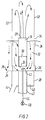
- FIGS 1, 2 and 4 of the drawings show a schematic representation of coating apparatus 10 according to the invention.
- the apparatus 10 includes a substantially closed chamber 12 defined by a plurality of upstanding side and end walls, 14 and 16 respectively, and a roof 18.
- the interior of the chamber 12 is divided into a plurality of cells 20, here shown as being seven in number, by a plurality of longitudinally spaced, upstanding partitions 22 which extend transversely between the opposed side walls 14 of the apparatus 10, and have their upper ends spaced below the roof 18 to define a plenum space 52.
- each cell 20 Within the lower portion of each cell 20 is positioned, substantially vertically disposed, a duct 24, that is desirably of hollow, rotation symmetrical form but which may be of conical or other shapes.
- the duct 24 has its lower end 26 vertically spaced from the bottom of the cell 20, defined by a gas distributor plate 28, with the upper end 29 spaced well below the top of the partition 22.
- the ducts 24 divide each cell 20 into a coating zone 30 defined by the interior region of the duct and a subsidence zone 32 which occupies the space exteriorly of the duct.
- the cross section of the cell 20 shall preferably be of regular shape, e.g., substantially rectangular, circular, hexagonal, or octogonal, or combinations thereof.
- the diameter of the duct 24 shall preferably be between 100 and 250 mm (approximately 4 to 10 inches).
- the height of the duct 20 shall preferably be between 400 and 1,000 millimeters (approximately 15 to 40 inches).
- the adjustable distance between the lower end of the duct 26 and the gas distributor plate 28 shall preferably be between 5 to 50 mm (about 5/8 to 2 inches) more preferably between 10 and 30 mm.
- the area of the cross section of the subsidence zone 32 shall preferably be three to six times that of the duct 24.
- the height of the partition 22 over the upper end of the duct 29 shall preferably be between 1.5 and 3 meters (approximately 5 to 10 feet), enough to prevent particles flying over the partition into adjacent cells.
- Each of the partitions 22 contains a transversely elongated opening 34 for connecting adjacent cells 20 in series.
- Each of the openings 34 is provided with a vertically adjustable closure plate 36 that operates to increase or decrease the overflow height through the partition 22 as well as increase or decrease the size of the opening 34 in order to control the rate of transfer of particles to the succeeding cell.
- each of the partitions 22 contains an opening 35 disposed adjacent the bottom of each cell 20 for connecting adjacent cells in series.
- Each of the openings 35 is provided with a closure plate 37 that effects the transfer of particles to succeeding cells when charging and emptying the apparatus.
- the gas distributor plate 28 is advantageously made common to all of the cells 20 and is a perforated plate that separates the chamber 12 from operating gas supply apparatus, which is indicated generally as 38 in the drawings.
- the gas distributor plate 28 may be formed as a substantially flat plate containing a plurality of openings 39 as represented in the drawings hereof. The number of holes per unit of plate area is preferably greater in the coating zone than in the subsidence zone.
- the gas distributor plate 28 may be formed of a heavy woven screen material (not shown). In either event, the size of the perforations or openings in the plate shall be such as to prevent the particles from falling through the plate from the cells 20 to the subadjacent gas supply apparatus 38.
- Gas supply apparatus 38 includes in association with each cell 20, a manifold chamber having a supply pipe 41 for supplying conditioned bed gas in amounts regulated by appropriate valves (not shown) upwardly into the subsidence zone 32 of the cell.
- a conductor 42 Concentrically placed within the manifold chamber 40 is a conductor 42 containing valving (not shown) for supplying conditioned gas into the coating zone 30 within the interior of the duct 24.
- the gas employed for system operation is typically air, but may also be other gases such as nitrogen, carbon dioxide, or similar gases, or mixtures thereof whose properties are substantially inert with respect to the coating and particulate material being processed.
- the operating gas is supplied in regulated amounts to the cells 20 at an elevated temperature to provide drying.
- the temperature is selected in dependance of the nature of the liquid carrier and the thermal stability of active ingredient.
- the coating material which may be dissolved, emulsified or dispersed in an organic solvent or mixture of solvents, is supplied to the coating zone 30 through an atomizing nozzle 43 at the terminal end of a supply pipe 44 containing a flow control valve 46.
- Coating materials suitable for use in the process include sulfur, petroleum waxes, chemical resins, and the like.
- the nozzle 43 is placed between the gas distribution plate 28 and the lower end 26 of the tube 24.
- the nozzle 43 may be positioned within the tube 24 adjacent its lower end 26, or even flush with the gas distributor plate 28, as desired, provided the spray from the nozzle 43 is directed upwardly into the coating zone 30 within the interior of the tube 24.
- particulate materials in the form of granules, particles, prills, or the like, as a substrate or core are processed on a continuous basis through a series of coating cells 20, in each of which a specified portion of the total coating material is applied while the particles are caused to circulate at a controlled rate through the coating zone 30 in each cell.
- a series of coating cells 20 in each of which a specified portion of the total coating material is applied while the particles are caused to circulate at a controlled rate through the coating zone 30 in each cell.
- the described invention contemplates the apparatus 10 being provided with two or more cells 20.
- the probability of a particle not being sufficiently coated in one cell, or remaining for an extended period in an excessive number of cells, is adequately small for many practical applications. This is graphically illustrated in Figure 7. It will appear that only 9% of the particles will exit the apparatus before having been retained for 50% of the average residence time. Only 8% of the particles will be retained for more than 150% of the average residence time. It is obvious that the apparatus must be constructed in such a way that residence time distributions close to the theoretical ones can be obtained.
- the apparatus 10 operates in the following way: Conditioned operating gas is supplied in controlled amounts through the gas distributor plate 28 from the manifold chamber 40 and from the gas conductor 42. Operating gas to the cell 20 is regulated in such a manner that the velocity of the gas admitted to the coating zone 30 exceeds that supplied to the subsidence zone 32. Simultaneously therewith, coating material in a solvent carrier is introduced at a controlled, uniform rate into the coating zone 30 as a finely atomized spray through the nozzle 43. When there is more than one duct 24 in a cell, there is a corresponding number of coating zones 30 in each cell.
- one duct 24 is substantially centrally disposed in each cell, it is conceivable to employ more than one duct in each cell with a corresponding number of coating zones 30.
- Operating gas flows to the respective zones 30 and 32 are such that particles introduced into the gas streams are carried in the high velocity gas stream through the coating zone within the duct 24 and pass through the spray of coating material from the coating spray nozzle 43 whereby droplets of coating material impinge on the surface of the particles during their residence time within the coating zone.
- the particles Upon emerging from the top end of the coating zone 30, the particles are discharged into the more quiescent, lower velocity region thereabove and fall down into the subsidence zone 32 wherein the effects of gravity and the upwardly directed lower velocity stream of operating gas therein cooperate to effect a cushioned migration of the particles in a plug flow manner downwardly through this zone.
- the evaporation of the solvent part of the coating starts in the upper end of the coating zone 30, and continues in the lower velocity region. A fraction of the particles corresponding to the feed rate to the apparatus 10 will migrate through opening 34 into the succeeding cell. Within the subsidence zone 32, the evaporation of the solvent is completed, leaving a compact layer of the coating material on each particle. Adjacent to the bottom of each cell 20, the particles re-enter the higher velocity gas flow to the coating zone 30, whereby the particles are recirculated through the coating spray to acquire another layer of coating material.
- a preferred embodiment of the apparatus according to the invention includes means for exhausting spent gas from the apparatus and for recirculating it as operating gas through the apparatus.
- particulate material to be processed is charged to the apparatus 10 via the particle inlet conduit 48 which communicates with the first cell 20 in the series. Following processing in each cell 20 in the aforementioned manner, the particles are transferred in series flow to the succeeding cells through the openings 34 in the respective partitions until the particles emerge from the terminal cell via outlet conduit 50 as final product having a surface coating of the desired thickness.
- the transfer from one cell to the next is normally accomplished by gravity flow. It is obvious that this will require a level difference between the cells. For constructional reasons, this is inconvenient when many cells are required.
- the transfer from one cell to the next can also be assisted by other means not shown, e.g., by blow pipes where compressed gas jets push the particles forward.
- Control of the application of coating material to the substrate particle in each cell 20 can be accurately maintained because, as the weight of particulate materials passing through each cell on a time basis, is controllable by control of the rate of charge of particulate via inlet conduit 48 and, since the supply of coating material to the coating zones 30 is maintained constant, the wieght of coating material applied to the particulates passing through each cell is determinable.
- the number of layers of coating material applied to each particle can be determined.
- the primary controlling factor in the operation of the apparatus is the available bottom opening of the tube 24 and the amount of high velocity operating gas supplied to the coating zone 30 therein.
- the primary controlling factor in the operation of the apparatus is the available bottom opening of the tube 24 and the amount of high velocity operating gas supplied to the coating zone 30 therein.
- the coating cells are performed and function as described in international patent application PCT/DK95/00040 incorporated herein by reference.
- an annular aperture exists around the nozzle 43, through which aperture most of the gas entering the coating zone 30 is injected, while none or only a minor gas flow penetrates the gas distributing means 28 in the area immediately surrounding the annular aperture.
- gas guiding walls are provided together with means for imparting a swirling movement to an accelerating flow of gas upwards through the annular aperture around the nozzle which atomizes the coating liquid.
- the process is operated to obtain a coated product that is most cost effective. This is a product that meets a market need and is produced at minimum cost.
- the stream of operating gas delivered to the subsidence zone 32 in the respective cells 20 has flow rates controlled to between about 0.6 meters per second and about 0.9 meters per second and that delivered to the coating zone 30 is delivered at flow rates of between about 8 meters per second and 15 meters per second.
- Cross-sectional area of duct 24 0.0324 m 2 (0.35 sq. ft.)
- Cross-sectional area of subsidence zone 32 0.1426 m 2 (1.53 sq.
- Example 1 Repeat the conditions of Example 1 using a setting of the bottom opening of duct 24 and a flow of operating gas thereto at a rate of about 9 meters per second to cause an average particle to pass thorugh the coating zone 30 in each cell eight times during the 8.57 minutes residence time.
- the prill product comprises 97% particulate core material and 3% coating material deposited in fifty-six layers.
- Example 1 Repeat the conditions of Example 1 using a setting of the bottom opening of duct 24 and a flow of operating gas thereto at a rate of about 10 meters per second to cause an average particle to pass through the coating zone in each cell twelve times during residence in each cell.
- the prill product comprises 97% particulate core material and 3% coating material deposited in the form of eighty-four layers on each particle.
- Example 1 using 10 kg per hour of coating material per 484 kg per hour core material and an operating gas velocity of 8 meters per second to the coating zone 30 and a gas velocity of 0.6 m/s in the subsidence zone 32.
- the prill product comprises 97.98% core material and 2.02% coating material deposited in twenty-eight layers on each particle.
- Example 2 using 10 kg per hour of coating material per 485 kg per hour core material, a gas velocity of 9 meters per second and a gas velocity of 0.6 m/s in the subsidence zone.
- the prill product comprises 97.98% core material and 2.02% coating material deposited in fifty-six layers on each particle.
- Example 3 using 10 kg per hour of coating material per 485 kg per hour core material using a gas velocity of 10 meters per second.
- the prill product comprises 97.98% core material and 2.02% coating material deposited in the form of eighty-four layers on each particle.
- Example 3 using 485 kg per hour core material and 20 kg per hour coating material, a gas velocity of 10 meters per second and a gas velocity of 0.9 m/s in the subsidence zone.
- the prill product comprises 96.04% core material and 3.96% coating material.
- the coating comprises eighty-four layers on each particle.
- Example 7 using a setting of the bottom opening of duct 24 and a gas velocity of about 12 meters per second providing a coating of 188 layers on each particle.
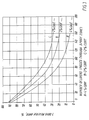
- Figure 3 is a diagram illustrating the rate of dissolution of fertilizer particles coated according to the above examples.
- the desired 7-day release rate for slow and controlled release fertilizers is generally below fifty percent.
- the prodution of coated fertilizers having varied amounts of coating will provide diverse rates of release of nutrients.
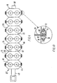
- FIGS 8, 9 and 10 wherein similar reference numerals are employed to designate similar elements of the inventive apparatus, illustrate the medial portion of one form of commercial production embodiment of the invention, the upper portion defining the plenum space 52 and the lower portion defining the manifold chamber 40 being omitted for sake of clarity.
- this embodiment of the invention in order to enhance the production capacity of thee equipment, includes a pair of tandem-connected ducts 24 disposed in each cell 20.
- the ducts 24 are adapted for angular displacement of their central axes as well as linear movement transversely of the respective cells.
- the coating apparatus comprises a series of cells 20 defined by vertical partitions 22 which extend transversely of the side walls 14.
- Particle outlet 50 penetrates the other end wall.
- the side walls 14 and partitions 22 are so-formed as to cooperatively define cells 20 that are essentially octagonal in section.
- Each partition contains an opening (not shown) which is framed on two sides by a pair of mounting brackets 60 for retaining a particle flow control plate 62 that covers the partition opening.
- Plate 62 is formed with an opening 64 which establishes flow communication between adjacent cells 20 and is movable by moving the plate 62 with respect to the brackets 60.
- Each cell 20 contains a pair of ducts 24 defining coating zones 30.
- the ducts 24 are connected in tandem by strapping plates 66 and 68 which secure the ducts adjacent their upper and lower ends, respecticely, and that enable the position of the ducts to be adjusted transversely of each cell.
- Means are provided to enable axial tilting of the ducts either toward or away from the respective partitions 22. Tilting of the duct pairs is effected by the connection of ends 70 of the respective strapping plates 66 and 68 to lead screws 72 disposed externally of opposed side walls 14 and threadedly attached via lock units 74 to mounting studs 76 having aligned openings 78 for reception of the screw.
- Each lead screw 72 is adapted to threadedly engage a collar 80 seated against rotation in an elongated opening formed by slots 32 in the plates. Accordingly, tilting of the ducts toward or away from the adjacent portion 22 is achieved by adjusting the relative fore and aft positions of the respective upper and lower ends of the connected ducts 24 by rotation of the screws 72 within the collar 80. In practice, angular displacements of the ducts 24 of up to about five degrees is contemplated with adjustment capability of between two and three degrees being preferred.
- another element of particle flow regulation is obtained by the ability to vertically adjust the position of the flow control plate 62 on each partition and, thereby, the location of the opening 64 that establishes communication between adjacent cells 20.
- an increase in particle flow between adjacent cells can also be obtianing by lowering the position of the opening 64 in the respective partitions 22.
- a decrease in particle flow rate between succeeding cells with a concomitant increase in particle recirculation through the coating zones 30 is accomplished by tilting the ducts 24 away from the parition 22 and/or by moving the flow control plate 62 to raise the opening 64 therein.
- the described apparatus advantageouly contains viewing windows 84 provided in a side wall 14 of each cell to permit observation of the various stages of the particle-coating process. Also, in the described arrangement, the closure 35 at the bottom of each cell is pivotally secured to the partition wall and an operating handle 86 is provided exteriorly of each cell whereby the closure can be moved between its open and closed positions and the loading and unloading of the apparatus facilitated.
Landscapes
- Chemical & Material Sciences (AREA)
- Organic Chemistry (AREA)
- Chemical Kinetics & Catalysis (AREA)
- Application Of Or Painting With Fluid Materials (AREA)
- Glanulating (AREA)
- General Preparation And Processing Of Foods (AREA)
Claims (25)
- Vorrichtung zum Auftragen von Beschichtungen auf separate Teilchen, umfassend:Mittel (14, 16, 18) zum Abgrenzen einer im wesentlichen geschlossenen Kammer (12);eine Mehrzahl über die Länge der Kammer in Abständen voneinander angeordnete Trennwände (22), die die Kammer in eine Mehrzahl von Zellen (20) einteilen;im wesentlichen vertikal verlaufende Führungsmittel (24) mit offenen oberen und unteren Enden, die gegenüber angrenzenden oberen und unteren Flächen der Kammer vertikal in Abstand angeordnet sind;Gasverteilungsmittel (28) zum Zuführen von Betriebsgas zum Boden jeder Zelle, und Leiten des Gases in senkrechten Strömen zum oberen Teil der Zelle, welche Mittel Anordnungen zum Leiten einen ersten Gasstroms durch das Innere der Leitung zum Erzeugen eines Hochgeschwindigkeits-Gasstroms darin, und eines zweiten Gasstroms ausserhalb der Leitung mit einer kleineren Geschwindigkeit als jene des ersten Gasstroms beinhalten;Mittel (43) zum Zuführen von Beschichtungsmaterial als eine diffuse Zerstäubung in das Innere der Leitung;Mittel (48) zur Beförderung zu beschichtender separater Teilchen zu einer Zelle am Ende der Kammer, wobei diese Teilchen zwecks gesteuerter Zirkulation durch die betreffende Zelle aufwärts durch das Innere der vertikalen Extrusionsleitung in Kontakt mit der darin befindlichen Zerstäubung des Beschichtungsmaterials, und abwärts in eine Verweilzone (32) ausserhalb der Leitung im Betriebsgas mitgeführt werden;Mittel (50) zum Entladen von beschichtetem Material aus einer Zelle an dem anderen Ende der Kammer;Mittel (56) zum Entladen von Betriebsgas aus einer oberen Zone der Kammer; undMittel die in jeder der Trennwände (22) Öffnungen (34) bilden, zum Zustandebringen des Strömens der Teilchen in aufeinanderfolgende Zellen.
- Vorrichtung nach Anspruch 1, in welcher das Führungsmittel aus einem hohlen, im wesentlichen rotationssymmetrischen Kanal besteht.
- Vorrichtung nach Anspruch 2, in welcher der Kanal im wesentlichen in der Mitte der Zelle angeordnet ist.
- Vorrichtung nach Anspruch 1, in welcher das Beschichtungsmaterial als Tropfen einer Lösung, Emulsion oder Dispersion des Beschichtungsmaterials in einem Lösungsmittel zugeführt wird, und das Betriebsgas in einer zum Verdampfen des Lösungsmittels ausreichend hohen Temperatur zugeleitet wird.
- Vorrichtung nach Anspruch 1 einschliesslich beweglicher Verschlüsse (62) zum Verschliessen der Öffnungen, welche Verschlüsse zum Einstellen der Öffnungen zum Steuern des Teilchenstroms zwischen aufeinanderfolgenden Zellen betätigt werden können.
- Vorrichtung nach Anspruch 1 einschliesslich Mitteln zum Ableiten von verbrauchtem Gas aus der Vorrichtung und dessen Rückführung als Betriebsgas durch die Vorrichtung.
- Vorrichtung nach Anspruch 6 einschliesslich einer Gasableitungsleitung aus der Kammer und Gasinduktormitteln in der Leitung zum Entfernen von verbrauchtem Betriebsgas aus der Kammer.
- Vorrichtung nach Anspruch 1 einschliesslich Mitteln zum winkeligen Verschieben der Leitungsachse im Verhältnis zu einer senkrechten Lage zum Justieren der Überführungsmenge von Teilchen in aufeinanderfolgende Zellen.
- Vorrichtung nach Anspruch 6 einschliesslich in der Gasstromrichtung stromabwärts angeordneten Mitteln zum Abscheiden von Lösungsmitteldämpfen aus dem Betriebsgas, wonach das Lösungsmittel und das Betriebsgas als Verfahrensmaterial durch die Vorrichtung rückgeführt werden können.
- Vorrichtung nach Anspruch 1, in welcher sich die Teilchen in einer idealen Strömung nach unten in die Verweilzone bewegen.
- Vorrichtung nach Anspruch 1 einschliesslich Mitteln zum Abgrenzen einer niedrigen Gasgeschwindigkeitszone hinter dem Entladeende der Beschichtungszone in jeder Zelle, bei welcher Gasgeschwindigkeit Teilchen in die Verweilzone der Zelle überführt werden.
- Vorrichtung nach Anspruch 1 einschliesslich Mitteln zum unabhängigen Steuern des Stroms von Betriebsgas zu den Beschichtungs- bzw. Verweilzonen, wobei die Rückführung von Teilchen durch die Beschichtungszone reguliert werden kann.
- Vorrichtung nach Anspruch 1, einschliesslich justierbarer Überlaufittel zum Regulieren der Entnahme von beschichteten Produkten aus der Kammer.
- Vorrichtung nach Anspruch 1, in welcher das Führungsmittel eine Mehrzahl innerhalb jeder Zelle im wesentlichen in Abstand von deren Wänden angeordnete Kanäle umfasst.
- Vorrichtung nach Anspruch 14, in welcher das Führungsmittel in jeder Zelle ein Paar Tandem-verbundene, in seitlichem Abstand angeordnete Kanäle umfasst.
- Vorrichtung nach Anspruch 15 einschliesslich Mitteln zum Einstellen der Position dieser Kanäle innerhalb der Zellen.
- Vorrichtung nach Anspruch 16, in welcher die Positions-Justiermittel eine Vorrichtung zu einem gemeinsamen Winkelverstellen der Achse der Kanäle im Verhältnis zu senkrecht zwecks Justieren der Beförderungsmenge von Teilchen in aufeinanderfolgende Zellen umfasst.
- Vorrichtung nach einem der Ansprüche 8 oder 17, wonach das Achsen-verstellbare Mittel ein Paar in senkrechten Abständen angeordnete Bänder umfasst, die mit den Kanälen nahe deren oberen und unteren Enden verbunden sind, wobei die Enden der Bänder ausserhalb der Kammer angeordnet sind, sowie Mittel zum Einstellen der jeweiligen Positionen der betreffenden Bänder, um die Lage der oberen und unteren Enden der Kanäle zu variieren und dadurch deren Neigung zu ändern.
- Verfahren zum Auftragen von Beschichtungen auf separate Teilchen, umfassend folgende Stufen:Zufuhr von Teilchenmaterial zu einer im wesentlichen geschlossen Kammer;Leiten der Teilchen durch eine innerhalb der Kammer angeordnete Mehrzahl von Zellen;innerhalb jeder Zelle, Zirkulieren der Teilchen zwischen Gasströmen in gleicher Richtung, die eine Hochgeschwindigkeitszone ergeben, und einer Verweilzone mit kleinerer Geschwindigkeit;Zufuhr von Beschichtungsmaterial in einer Zerstäubung zum Gasstrom in der Hochgeschwindigkeitszone, um dadurch mit den zirkulierenden Teilchen in Kontakt zu kommen;Steuern der Geschwindigkeit der Gasströme in den betreffenden Zonen zum Rückführen der Teilchen zwischen den betreffenden Zonen vor deren Entladen in eine darauffolgende Zelle; undEntnahme von beschichtetem Produkt aus der letzten Zelle der Kammer.
- Verfahren nach Anspruch 19 einschliesslich der Stufe des Zuführens des Beschichtungsmaterials in aufgelöstem, emulgiertem oder dispergiertem Zustand in einem Träger des Lösungsmittels.
- Verfahren nach Anspruch 19 einschliesslich des Erhitzens des durch die Zellen geleiteten Gasstroms auf eine zum Verdampfen des Beschichtungsmaterials auf den Teilchen ausreichende Temperatur.
- Verfahren nach Anspruch 19 einschliesslich der Stufe des Kontrollierens der Dicke des auf die Teilchen aufgetragenen Beschichtungsmaterials durch unabhängiges Steuern der Geschwindigkeiten der Gasströme in den betreffenden Zonen jeder Zelle.
- Verfahren nach Anspruch 22 einschliesslich der Stufe des aufeinanderfolgenden Leitens der Teilchen durch eine Mehrzahl von Zellen.
- Verfahren nach Anspruch 19, bei welchem Harnstoffteilchen mit einem in Wasser langsam löslichen Polymer beschichtet werden.
- Verfahren nach Anspruch 19, einschliesslich der Stufe des winkeligen Variierens der Lage der Hochgeschwindigkeitszone zum Steuern der Zirkulation von Teilchen.
Applications Claiming Priority (3)
| Application Number | Priority Date | Filing Date | Title |
|---|---|---|---|
| US206174 | 1988-06-13 | ||
| US08/206,174 US5470387A (en) | 1994-03-07 | 1994-03-07 | Continuous multicell process and apparatus for particle coating including particle recirculation |
| PCT/DK1995/000103 WO1995024263A1 (en) | 1994-03-07 | 1995-03-07 | An apparatus and a process for continuous particle coating |
Publications (2)
| Publication Number | Publication Date |
|---|---|
| EP0749353A1 EP0749353A1 (de) | 1996-12-27 |
| EP0749353B1 true EP0749353B1 (de) | 1997-10-15 |
Family
ID=22765284
Family Applications (1)
| Application Number | Title | Priority Date | Filing Date |
|---|---|---|---|
| EP95911223A Expired - Lifetime EP0749353B1 (de) | 1994-03-07 | 1995-03-07 | Apparat und verfahren zur kontinuierlichen beschichtung von teilchen |
Country Status (7)
| Country | Link |
|---|---|
| US (2) | US5470387A (de) |
| EP (1) | EP0749353B1 (de) |
| JP (1) | JPH09509883A (de) |
| AT (1) | ATE159185T1 (de) |
| AU (1) | AU1889695A (de) |
| DE (1) | DE69500887D1 (de) |
| WO (1) | WO1995024263A1 (de) |
Families Citing this family (24)
| Publication number | Priority date | Publication date | Assignee | Title |
|---|---|---|---|---|
| NZ331531A (en) * | 1997-09-04 | 2000-01-28 | Toyo Engineering Corp | method for granulation and granulator |
| US6376018B1 (en) | 1998-06-17 | 2002-04-23 | Wilfred C. Kittler, Jr. | Method for the production of unsupported thin film particles |
| US6312521B1 (en) * | 1998-12-14 | 2001-11-06 | Primera Foods Corporation | Apparatus and process for coating particles |
| US6368658B1 (en) * | 1999-04-19 | 2002-04-09 | Scimed Life Systems, Inc. | Coating medical devices using air suspension |
| US6730349B2 (en) * | 1999-04-19 | 2004-05-04 | Scimed Life Systems, Inc. | Mechanical and acoustical suspension coating of medical implants |
| DK1064990T3 (da) | 1999-06-29 | 2004-05-24 | Aeromatic Fielder Ag | Fremgangsmåde til granulering af et partikelformet materiale |
| NO312712B1 (no) | 1999-12-15 | 2002-06-24 | Norsk Hydro As | En sorterende fluid bed granulator samt fremgangsmåte for fluid bed granulering |
| DE10016906B4 (de) * | 2000-04-05 | 2005-06-16 | Braunschweigische Maschinenbauanstalt Ag | Verfahren zur Herstellung eines Gelierzuckers |
| DE10016905B4 (de) * | 2000-04-05 | 2005-06-16 | Braunschweigische Maschinenbauanstalt Ag | Verfahren zur Herstellung eines Gelierhilfsmittels |
| KR20030046520A (ko) | 2000-11-06 | 2003-06-12 | 캐보트 코포레이션 | 개질된 산소 환원된 밸브 금속 산화물 |
| US20030159703A1 (en) * | 2002-02-22 | 2003-08-28 | Zuyin Yang | Flavored carbon useful as filtering material of smoking article |
| US7001369B2 (en) | 2003-03-27 | 2006-02-21 | Scimed Life Systems, Inc. | Medical device |
| DE10322062A1 (de) * | 2003-05-15 | 2004-12-02 | Glatt Ingenieurtechnik Gmbh | Verfahren und Vorrichtung zum Aufbringen von Flüssigkeiten in eine Feststoffströmung eines Strahlschichtapparates |
| NL1025954C2 (nl) * | 2004-04-15 | 2005-10-18 | Dsm Ip Assets Bv | Werkwijze voor het optimaliseren van een fluïdbed granulator. |
| DE602006011793D1 (de) | 2006-05-02 | 2010-03-04 | Gea Process Engineering As | Agglomerationsvorrichtung und verfahren zur herstellung von agglomerierten teilchen |
| CN101573576A (zh) * | 2006-12-29 | 2009-11-04 | 巴塞尔聚烯烃意大利有限责任公司 | 干燥聚合物的方法和设备 |
| CA2678931C (en) * | 2007-02-21 | 2014-09-16 | Smithkline Beecham Corporation | Continuous coating of pellets |
| CN102744010B (zh) * | 2012-07-24 | 2014-04-23 | 陈林书 | 一种喷浆造粒方法 |
| ES2732292T3 (es) * | 2013-04-03 | 2019-11-21 | Glatt Ingtech Gmbh | Estrella rotativa de secado para el tratamiento de partículas sólidas |
| DE102013005921A1 (de) | 2013-04-03 | 2014-10-09 | Glatt Ingenieurtechnik Gmbh | Fluidisierungsapparat |
| CA2923071A1 (en) * | 2013-09-27 | 2015-04-02 | Bexo As | Fluid bed classification elements |
| US9901706B2 (en) | 2014-04-11 | 2018-02-27 | Boston Scientific Scimed, Inc. | Catheters and catheter shafts |
| WO2016205242A1 (en) * | 2015-06-15 | 2016-12-22 | Ald Nanosolutions, Inc. | Continuous spatial atomic layer deposition process and apparatus for applying films on particles |
| KR102627888B1 (ko) * | 2021-09-23 | 2024-01-23 | 주식회사 뉴파워 프라즈마 | 코팅 장치와 가스 공급 부재 및 코팅 방법 |
Family Cites Families (14)
| Publication number | Priority date | Publication date | Assignee | Title |
|---|---|---|---|---|
| US3241520A (en) * | 1964-10-19 | 1966-03-22 | Wisconsin Alumni Res Found | Particle coating apparatus |
| HU168255B (de) * | 1972-12-13 | 1976-03-28 | ||
| GB1481034A (en) * | 1974-10-24 | 1977-07-27 | Rank Xerox Ltd | Method of producing coated carrier particles for toner particles |
| US4008685A (en) * | 1976-04-20 | 1977-02-22 | Westinghouse Electric Corporation | Electrostatic fluidized bed build control |
| DE3007711C2 (de) * | 1980-02-29 | 1987-01-02 | Kernforschungsanlage Jülich GmbH, 5170 Jülich | Anströmeinheit für einen Wirbelschichtofen |
| DE3021037C2 (de) * | 1980-06-03 | 1982-06-16 | Kernforschungsanlage Jülich GmbH, 5170 Jülich | Vorrichtung und Verfahren zum Entladen eines Wirbelschichtofens für die Beschichtung von Hochtemperaturreaktor (HTR)-Brennstoffen |
| DE3237303A1 (de) * | 1982-10-08 | 1984-04-12 | Glatt GmbH, 7851 Binzen | Vorrichtung fuer wirbelschichtverfahren sowie damit durchfuehrbares verfahren |
| DE3244963C2 (de) * | 1982-12-04 | 1985-08-14 | Buckau-Walther AG, 4048 Grevenbroich | Vorrichtung zur Abwasserreinigung |
| JPS6274443A (ja) * | 1985-09-27 | 1987-04-06 | Toyo Eng Corp | 粒子の加工方法 |
| US5198029A (en) * | 1989-08-01 | 1993-03-30 | Gte Products Corporation | Apparatus for coating small solids |
| US5189029A (en) * | 1990-04-23 | 1993-02-23 | Bo-Dekk Ventures, Ltd. | Indacene compounds and methods for using the same |
| US5211985A (en) * | 1991-10-09 | 1993-05-18 | Ici Canada, Inc. | Multi-stage process for continuous coating of fertilizer particles |
| US5236503A (en) * | 1991-10-28 | 1993-08-17 | Glatt Air Techniques, Inc. | Fluidized bed with spray nozzle shielding |
| US5476528A (en) * | 1993-12-20 | 1995-12-19 | Tennessee Valley Authority | System for improving material release profiles |
-
1994
- 1994-03-07 US US08/206,174 patent/US5470387A/en not_active Expired - Fee Related
-
1995
- 1995-03-07 DE DE69500887T patent/DE69500887D1/de not_active Expired - Lifetime
- 1995-03-07 AU AU18896/95A patent/AU1889695A/en not_active Abandoned
- 1995-03-07 WO PCT/DK1995/000103 patent/WO1995024263A1/en not_active Ceased
- 1995-03-07 AT AT95911223T patent/ATE159185T1/de active
- 1995-03-07 JP JP7523166A patent/JPH09509883A/ja active Pending
- 1995-03-07 EP EP95911223A patent/EP0749353B1/de not_active Expired - Lifetime
- 1995-08-23 US US08/518,313 patent/US5648118A/en not_active Expired - Fee Related
Also Published As
| Publication number | Publication date |
|---|---|
| US5470387A (en) | 1995-11-28 |
| DE69500887D1 (de) | 1997-11-20 |
| WO1995024263A1 (en) | 1995-09-14 |
| US5648118A (en) | 1997-07-15 |
| EP0749353A1 (de) | 1996-12-27 |
| ATE159185T1 (de) | 1997-11-15 |
| AU1889695A (en) | 1995-09-25 |
| JPH09509883A (ja) | 1997-10-07 |
Similar Documents
| Publication | Publication Date | Title |
|---|---|---|
| EP0749353B1 (de) | Apparat und verfahren zur kontinuierlichen beschichtung von teilchen | |
| EP0607363B1 (de) | Vorrichtung und verfahren zum beschichten von partikeln | |
| US4217127A (en) | Process for producing urea granules | |
| US5437889A (en) | Fluidized bed with spray nozzle shielding | |
| EP0574173B1 (de) | Wirbelschichtapparat zum überziehen von Teilchen | |
| RU2595696C2 (ru) | Гранулирование мочевины в псевдоожиженном слое и соответствующий аппарат | |
| AU2009243258B2 (en) | Method and device for processing of granules | |
| US20150246333A1 (en) | Agglomeration apparatus and method for producing agglomerated particles | |
| KR850007367A (ko) | 과립의 제조방법 및 이의 장치 | |
| US8863686B2 (en) | Fluid bed apparatus for coating solid particles | |
| US5501874A (en) | Method of coating granular material and apparatus therefor | |
| DE2941637C2 (de) | ||
| US4370198A (en) | Method and apparatus for the recovery of the solid material content of solutions and/or suspensions as granules in a gas fluidized bed | |
| EP1040867B1 (de) | Verfahren und Vorrichtung zur kontinuierlichen Behandlung von Katalysatoren und Katalysatorträgern | |
| EP1407814B1 (de) | Verfahren und Vorrichtung mit Wirbelschichtanlage zur Herstellung von Granulaten | |
| EP1295633B1 (de) | Verfahren zum Beschichten von Teilchen | |
| US4332211A (en) | Granule producing apparatus | |
| US3475195A (en) | Process and apparatus for granulating paste | |
| KR830001389B1 (ko) | 과립 제조 장치 | |
| DE102004022102A1 (de) | Verfahren zur Verkapselung flüchtiger, oxidationsempfindlicher Substanzen sowie von Duft- und Geschmacksstoffen in Granulatform | |
| WO1995019838A1 (en) | Formation of pelleted fertiliser products | |
| DD155587A1 (de) | Zwei-oder mehrstufige wirbelschichtapparatur zur erzeugung von granulaten | |
| DE102004028883A1 (de) | Verfahren zur Granulation von Malzextrakten | |
| Page et al. | Pharmainfo. net |
Legal Events
| Date | Code | Title | Description |
|---|---|---|---|
| PUAI | Public reference made under article 153(3) epc to a published international application that has entered the european phase |
Free format text: ORIGINAL CODE: 0009012 |
|
| 17P | Request for examination filed |
Effective date: 19960902 |
|
| AK | Designated contracting states |
Kind code of ref document: A1 Designated state(s): AT BE CH DE DK ES FR GB IE IT LI NL SE |
|
| GRAG | Despatch of communication of intention to grant |
Free format text: ORIGINAL CODE: EPIDOS AGRA |
|
| GRAH | Despatch of communication of intention to grant a patent |
Free format text: ORIGINAL CODE: EPIDOS IGRA |
|
| 17Q | First examination report despatched |
Effective date: 19970218 |
|
| GRAH | Despatch of communication of intention to grant a patent |
Free format text: ORIGINAL CODE: EPIDOS IGRA |
|
| GRAA | (expected) grant |
Free format text: ORIGINAL CODE: 0009210 |
|
| AK | Designated contracting states |
Kind code of ref document: B1 Designated state(s): AT BE CH DE DK ES FR GB IE IT LI NL SE |
|
| PG25 | Lapsed in a contracting state [announced via postgrant information from national office to epo] |
Ref country code: NL Free format text: LAPSE BECAUSE OF FAILURE TO SUBMIT A TRANSLATION OF THE DESCRIPTION OR TO PAY THE FEE WITHIN THE PRESCRIBED TIME-LIMIT Effective date: 19971015 Ref country code: LI Effective date: 19971015 Ref country code: IT Free format text: LAPSE BECAUSE OF FAILURE TO SUBMIT A TRANSLATION OF THE DESCRIPTION OR TO PAY THE FEE WITHIN THE PRESCRIBED TIME-LIMIT;WARNING: LAPSES OF ITALIAN PATENTS WITH EFFECTIVE DATE BEFORE 2007 MAY HAVE OCCURRED AT ANY TIME BEFORE 2007. THE CORRECT EFFECTIVE DATE MAY BE DIFFERENT FROM THE ONE RECORDED. Effective date: 19971015 Ref country code: FR Free format text: LAPSE BECAUSE OF FAILURE TO SUBMIT A TRANSLATION OF THE DESCRIPTION OR TO PAY THE FEE WITHIN THE PRESCRIBED TIME-LIMIT Effective date: 19971015 Ref country code: ES Free format text: THE PATENT HAS BEEN ANNULLED BY A DECISION OF A NATIONAL AUTHORITY Effective date: 19971015 Ref country code: DK Free format text: LAPSE BECAUSE OF NON-PAYMENT OF DUE FEES Effective date: 19971015 Ref country code: CH Effective date: 19971015 Ref country code: BE Free format text: LAPSE BECAUSE OF FAILURE TO SUBMIT A TRANSLATION OF THE DESCRIPTION OR TO PAY THE FEE WITHIN THE PRESCRIBED TIME-LIMIT Effective date: 19971015 Ref country code: AT Free format text: LAPSE BECAUSE OF FAILURE TO SUBMIT A TRANSLATION OF THE DESCRIPTION OR TO PAY THE FEE WITHIN THE PRESCRIBED TIME-LIMIT Effective date: 19971015 |
|
| REF | Corresponds to: |
Ref document number: 159185 Country of ref document: AT Date of ref document: 19971115 Kind code of ref document: T |
|
| REG | Reference to a national code |
Ref country code: CH Ref legal event code: EP |
|
| REF | Corresponds to: |
Ref document number: 69500887 Country of ref document: DE Date of ref document: 19971120 |
|
| PG25 | Lapsed in a contracting state [announced via postgrant information from national office to epo] |
Ref country code: SE Effective date: 19980115 |
|
| PG25 | Lapsed in a contracting state [announced via postgrant information from national office to epo] |
Ref country code: DE Free format text: LAPSE BECAUSE OF FAILURE TO SUBMIT A TRANSLATION OF THE DESCRIPTION OR TO PAY THE FEE WITHIN THE PRESCRIBED TIME-LIMIT Effective date: 19980116 |
|
| NLV1 | Nl: lapsed or annulled due to failure to fulfill the requirements of art. 29p and 29m of the patents act | ||
| PG25 | Lapsed in a contracting state [announced via postgrant information from national office to epo] |
Ref country code: IE Free format text: LAPSE BECAUSE OF NON-PAYMENT OF DUE FEES Effective date: 19980307 |
|
| EN | Fr: translation not filed | ||
| REG | Reference to a national code |
Ref country code: CH Ref legal event code: PL |
|
| PLBE | No opposition filed within time limit |
Free format text: ORIGINAL CODE: 0009261 |
|
| STAA | Information on the status of an ep patent application or granted ep patent |
Free format text: STATUS: NO OPPOSITION FILED WITHIN TIME LIMIT |
|
| 26N | No opposition filed | ||
| PG25 | Lapsed in a contracting state [announced via postgrant information from national office to epo] |
Ref country code: GB Free format text: LAPSE BECAUSE OF NON-PAYMENT OF DUE FEES Effective date: 19990307 |
|
| GBPC | Gb: european patent ceased through non-payment of renewal fee |
Effective date: 19990307 |