EP0749376B1 - Zigarettenanzünderkörper, insbesondere für kraftfahrzeuge - Google Patents
Zigarettenanzünderkörper, insbesondere für kraftfahrzeuge Download PDFInfo
- Publication number
- EP0749376B1 EP0749376B1 EP95942255A EP95942255A EP0749376B1 EP 0749376 B1 EP0749376 B1 EP 0749376B1 EP 95942255 A EP95942255 A EP 95942255A EP 95942255 A EP95942255 A EP 95942255A EP 0749376 B1 EP0749376 B1 EP 0749376B1
- Authority
- EP
- European Patent Office
- Prior art keywords
- lighter
- shell
- masking
- sleeve
- body according
- Prior art date
- Legal status (The legal status is an assumption and is not a legal conclusion. Google has not performed a legal analysis and makes no representation as to the accuracy of the status listed.)
- Expired - Lifetime
Links
- 235000019504 cigarettes Nutrition 0.000 title description 11
- 230000000873 masking effect Effects 0.000 claims description 72
- 235000019506 cigar Nutrition 0.000 claims description 5
- 238000010292 electrical insulation Methods 0.000 claims description 3
- 238000005452 bending Methods 0.000 claims 1
- 210000002105 tongue Anatomy 0.000 description 34
- 238000010438 heat treatment Methods 0.000 description 19
- 239000000463 material Substances 0.000 description 7
- 230000000295 complement effect Effects 0.000 description 6
- 229920003023 plastic Polymers 0.000 description 6
- 238000009413 insulation Methods 0.000 description 4
- 239000002184 metal Substances 0.000 description 4
- 229910052751 metal Inorganic materials 0.000 description 4
- 238000000465 moulding Methods 0.000 description 4
- 230000015572 biosynthetic process Effects 0.000 description 3
- 230000000994 depressogenic effect Effects 0.000 description 3
- 230000036961 partial effect Effects 0.000 description 3
- 125000006850 spacer group Chemical group 0.000 description 3
- 230000008901 benefit Effects 0.000 description 2
- 230000000149 penetrating effect Effects 0.000 description 2
- 230000000284 resting effect Effects 0.000 description 2
- 230000002441 reversible effect Effects 0.000 description 2
- 238000009423 ventilation Methods 0.000 description 2
- RYGMFSIKBFXOCR-UHFFFAOYSA-N Copper Chemical compound [Cu] RYGMFSIKBFXOCR-UHFFFAOYSA-N 0.000 description 1
- 230000002159 abnormal effect Effects 0.000 description 1
- 230000004323 axial length Effects 0.000 description 1
- 238000010009 beating Methods 0.000 description 1
- 230000000903 blocking effect Effects 0.000 description 1
- 238000007664 blowing Methods 0.000 description 1
- 229910052802 copper Inorganic materials 0.000 description 1
- 239000010949 copper Substances 0.000 description 1
- 238000007599 discharging Methods 0.000 description 1
- 238000004519 manufacturing process Methods 0.000 description 1
- 210000000056 organ Anatomy 0.000 description 1
- 230000010355 oscillation Effects 0.000 description 1
- 238000013021 overheating Methods 0.000 description 1
- 230000002829 reductive effect Effects 0.000 description 1
- 230000001960 triggered effect Effects 0.000 description 1
Images
Classifications
-
- B—PERFORMING OPERATIONS; TRANSPORTING
- B60—VEHICLES IN GENERAL
- B60N—SEATS SPECIALLY ADAPTED FOR VEHICLES; VEHICLE PASSENGER ACCOMMODATION NOT OTHERWISE PROVIDED FOR
- B60N3/00—Arrangements or adaptations of other passenger fittings, not otherwise provided for
- B60N3/14—Arrangements or adaptations of other passenger fittings, not otherwise provided for of electrically-heated lighters
-
- B—PERFORMING OPERATIONS; TRANSPORTING
- B60—VEHICLES IN GENERAL
- B60Q—ARRANGEMENT OF SIGNALLING OR LIGHTING DEVICES, THE MOUNTING OR SUPPORTING THEREOF OR CIRCUITS THEREFOR, FOR VEHICLES IN GENERAL
- B60Q3/00—Arrangement of lighting devices for vehicle interiors; Lighting devices specially adapted for vehicle interiors
- B60Q3/20—Arrangement of lighting devices for vehicle interiors; Lighting devices specially adapted for vehicle interiors for lighting specific fittings of passenger or driving compartments; mounted on specific fittings of passenger or driving compartments
- B60Q3/275—Smoking-related fittings, e.g. cigarette lighters or ashtrays
-
- B—PERFORMING OPERATIONS; TRANSPORTING
- B60—VEHICLES IN GENERAL
- B60Q—ARRANGEMENT OF SIGNALLING OR LIGHTING DEVICES, THE MOUNTING OR SUPPORTING THEREOF OR CIRCUITS THEREFOR, FOR VEHICLES IN GENERAL
- B60Q3/00—Arrangement of lighting devices for vehicle interiors; Lighting devices specially adapted for vehicle interiors
- B60Q3/60—Arrangement of lighting devices for vehicle interiors; Lighting devices specially adapted for vehicle interiors characterised by optical aspects
- B60Q3/62—Arrangement of lighting devices for vehicle interiors; Lighting devices specially adapted for vehicle interiors characterised by optical aspects using light guides
- B60Q3/64—Arrangement of lighting devices for vehicle interiors; Lighting devices specially adapted for vehicle interiors characterised by optical aspects using light guides for a single lighting device
Definitions
- the present invention relates to a cigar lighter in particular for motor vehicle (cf. US-A-2 701 297, corresponding to the preamble of the independent claim).
- It relates more particularly to the ignition body that includes such a cigarette lighter.
- the ignition body serves as a receptacle with a removable heating cap provided with a heating body to light a cigar or cigarette and has a socket electrically conductive ignition, with bottom, bearing internally electrically insulated, via a fastener and a first piece of insulation electric, a socket outlet usually shaped bimetallic strip.
- This ignition socket has openings of clearance opposite the bimetal blades, suitable for being connected to the positive terminal of the voltage source, while the socket is suitable for being connected to the negative terminal of the source of tension.
- the ignition body is located in a region where there are many electric wires and / or cables.
- the ignition socket is threaded in a opening of a fixed wall of the vehicle, such as the switchboard edge or a console thereof used for fixing and mounting the ignition body, and is held captive using masking sleeve screwed onto a worn threaded part through the rear end of the ignition socket.
- the open front end of the masking sleeve is in abutment against the rear face of the fixed wall, while the open front end of the ignition socket has a generally transverse rim resting on the front or top face of an end ring of a ring illuminating, which ring, by its rear face, is supported on the front or upper face of the fixed wall.
- This fixed wall is thus sandwiched between the ring of the lighting ring and the open front end of the masking sleeve.
- the fixed wall is electrically conductive so that the return of current to ground is produced using said wall.
- the masking sleeve carries a source lighting, so that an opening must be created in said masking socket for lighting the illuminating ring.
- the object of the present invention is to overcome these disadvantages and therefore to create, in a simple and economical way, an ignition body with standard ignition socket and simplified masking, the assembly of which is carried out from the front of the fixed wall.
- an ignition body of the above-mentioned type is characterized in that the masking sleeve has a bottom adjacent and electrically connected to the bottom of the socket by being assembled to the ignition socket by through the through fastener to do this electrically insulated the bottoms of the ignition and masking, in that the illuminating ring surrounds the socket masking and has at least one fixing tab elastically deformable and clean to come into contact with the rear face of the fixed wall and in that means of fixing occurs between the masking sleeve and the ring light for fixing the masking sleeve to the ring illuminating.
- a unitary assembly is formed masking socket - ignition socket using a standard ignition socket and the masking socket is simplified because it is devoid, just like the socket ignition, threaded part.
- the illuminating ring allows mounting of all of the masking and ignition sockets from the front or front of the fixed wall. This ring is easily obtained by molding and is used to hang the masking sleeve and all of the above.
- the illuminating ring surrounds the masking ring and directly carries the light source.
- the lighting of the ring of the illuminating ring is thus best quality.
- the fixing means consist of latching means intervening between the illuminating ring and the masking sleeve.
- the illuminating ring has internally protruding notches suitable for engaging in associated openings in the wall of the socket masking. The illuminating ring is therefore in intimate contact with the masking sleeve.
- the free (or front) end of the sleeve masking is engaged centering in the ring of the ring illuminating.
- the masking sleeve is thus kept stably by the illuminating ring and the means of fixing, as well as the fixing tabs, are provided. The stresses in the lighting ring are therefore minimized.
- centering means intervene between the masking sleeve and the ignition sleeve.
- the masking sleeve may have legs obtained by cutting and folding in contact with the wall of the sleeve in the vicinity of the open end of the masking sleeve.
- These centering means are installed axially between the open end of the masking sleeve and the fixing means.
- the illuminating ring carries detachably a light box containing a bulb lighting.
- the lighting ring has a slide for mounting in the manner of a drawer of the light box. All this is easily achieved because, in a manner known per se, the illuminating ring is made of moldable plastic.
- angular indexing means intervene between the lighting ring and a washer electrical insulation carried externally by the sleeve ignition to facilitate threading of the unitary assembly aforementioned in the illuminating ring and realize so automatic fixing of the masking sleeve, the notches of latching means penetrating securely into their associated openings.
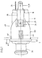
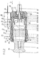
- a cigarette lighter for motor vehicle comprising a removable heating cap 30 and an ignition body 40 forming receptacle and socket for cap 30.
- the ignition body 40 has an ignition socket 6, electrically conductive, closed at the back by a bottom, a fixing member 14 passing through said bottom, a gripping member current 12 mounted inside the socket 6 and connected electrically by the fastener 14 to a first part power supply 19 mounted outside the socket 6, a first piece of electrical insulation 15 interposed between the outlet member 12 and the bottom of the socket 6, a second electrical supply part 17 mounted outside of the socket 6 while being adjacent to the bottom of the latter and connected electrically to said socket 6, a second piece of insulation electric 18 interposed between the first 19 and the second 17 electrical supply part, a safety element 16 having a safety tab, generally oriented axial, suitable for establishing a short circuit in the event of overheating of the ignition body 40, said fixing member 14, electrically conductive, passing through insulation parts electric 15.18 for assembly of power supply parts electric 19,17, the socket outlet member 12, and security element 16.
- the parts 6,12,14,16,17,19, here metallic, are therefore electrically conductive, while parts 15.18 are electrically insulating, being advantageously made of material moldable plastic.
- the fixing member 14 consists of a metal screw, alternatively in a rivet
- the gripping member of current 12 is a bimetallic strip
- the parts 17.19 consist of tongues generally axially oriented, here based on copper
- security element 16 is a bimetallic strip mounted head to tail compared to bimetallic strip 12, being distinct from it.
- These bimetallic strips 12,16 have a generally U-shaped section with a disc-shaped base and two tabs, overall diametrically opposite and axially oriented.
- the bimetallic discs 12,16 are in contact with one the other, the blades of bimetallic strip 16 passing through the bottom of the socket 6 through openings 28, while the socket 6 of form cylindrical, here in stamped sheet metal, present, facing the blades of the socket outlet bimetallic strip 12, two clearance openings 32, diametrically opposite and each also delimiting a tab 33 ( Figure 4) for retaining the plug 30 in waiting position.
- the first insulating part 15 forms an axial spacer interposed between the base of bimetallic strip 16 and the bottom of the socket 6.
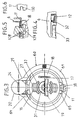
- the second insulating part 18 has the overall shape of a massive washer with a through central opening 31 for passage of the screw 14 and two lateral openings 27 for, on the one hand, the mounting of two parts curved 37 here convex (Figure 3), axially oriented, the second tab 17 and, on the other hand, the clearance housing of bimetallic strip 16, the free ends of which have a overall V-shaped section ( Figure 2) for contact punctual in the event of a short circuit with the convex parts 37, here curved in the shape of a semicircle, of the tongue 17.
- the opening 31 is stepped for defining a shoulder. It is on this shoulder that the base of the tongue rests. 19 in the form of a square. This base, parallel to the bottom of the socket 6, is perforated centrally with the formation of a chimney threaded for screwing the end of the screw 14.
- the tongue 19 therefore forms a nut.
- the tongue 17 generally also has a square shape with a base parallel to that of the tongue 19 and at the bottom of the sleeve 6.
- the insulating washer 18 therefore forms a spacer axial between the bases of the tabs 17.19 in favor of a bottom bounded by the stepped opening 31.
- the washer 18 also has (FIG. 3), overall perpendicular to the openings 27, an opening for passage in a complementary manner of the axial part of the tab 17.
- the opening 31 also delimits two grooves, diametrically opposed, for mounting in the manner of a drawer of the axial part, provided with a fold ( Figure 2), the tongue 19, which thus extends perpendicularly relative to tab 17.
- tabs 17,19 are immobilized and positioned (by cooperation of shapes) by the washer 18 and protrude axially with respect to the latter in opposite direction to the bottom of the ignition socket 6. These tabs 17,19 are shouldered the outside of the washer 18.
- the washer 18 therefore also forms a spacer in the transverse direction of Figure 2 between the tongues 17,19.
- Each opening 27 also has at its base two Argued grooves ( Figure 3) for threaded mounting of parts 37 like a drawer.
- These parts 37 come from from the base of the tongue 17 and extend axially towards the outside so that the fastening end of the tongue 17 has overall in section the shape of a U with two branches 37 in a semicircle.
- These parts 37 diametrically opposite, are in contact with the corresponding lower edge, shaped of an arc, of opening 27 (figure 3).
- Each opening 27 thus has (edges 2 and 3) an edge axially oriented upper, chamfered at each of its ends, two parallel side edges, overall perpendicular to the upper edge, and a lower edge, axially oriented, in the form of a defined semicircle laterally by the mounting grooves of the parts 37, said grooves affecting the lateral edges.
- the tabs of bimetallic strip 16 are distance each of the side and top edges of the opening 27, as well as part 37 concerned.
- the chamfers of the upper edges prevent contact during normal operation between, on the one hand, the rounded blade connection area bimetallic strip 16 at its base and the upper edge of the opening 27, and, on the other hand, between this upper edge and the V-shaped end of said blade.
- the base of the tongue 17 is in contact here directly with the bottom of a socket masking 11 surrounding the ignition socket 6 to mask its openings 32.
- No wire or cable can touch the blades of the 12 socket bimetallic strip, which can expand through the openings 32, knowing that in a motor vehicle the cigarette lighter is located in a region, for example in dashboard level, where many cables and wires pass electric. There is no risk of damaging the wires or cables, blow fuses and / or cause a fire.
- the rear bottom of the masking sleeve 11, electrically conductive, here cylindrical in pressed sheet metal, is in contact with the bottom of the ignition socket 6 and the screw 14 crosses electrically insulated said perforated bottoms centrally for this purpose.
- the insulating part 15, mounted mainly in the socket 6, has a central nose passing through the openings sockets 6,11 central, the base of the tongue 17 drilled centrally for this purpose, to enter the reduced diameter portion of the opening 31 of the washer 18.
- This central nose forming a chimney, is crossed by the screw 14, which allows a tight assembly of the parts 12,15,16,11,6,17,18,19 between them.
- the outer periphery of this nose has at least one flat cooperating with flats of complementary shape practiced in the openings coinciding with the bottoms of the sockets 6.11 and the washer 18, the tongues 17 and 19 also being immobilized by the washer 18 above. So we obtains a rotation lock, by cooperation of shapes, parts 15,16,6,11,17,18,19 with tightening of these on one side and on the other side of the sockets 11.6 thanks to the screw 14.
- the nose of the insulating piece 15 can have a polygonal shape for example square shape and so is even the aforementioned complementary openings.
- these openings and the nose of the part 15 can be cylindrical in shape, the part 15 having laterally, in a manner known per se, at least one cylindrical pin crossing the bottoms of the sockets 6,11 in a complementary manner and the washer 18.
- This pin then also crosses the base of the tongue 17 in a complementary manner or not.
- FIG. 5 More precisely (FIG. 5) the pin 129 of shape cylindrical through oblong openings 128 matched in sockets 6,11, the width openings 128 being equal to the mounting clearance near the diameter of the pin 129 which engages in a notch 130 in the form of U made in the lateral edge of the base of the tongue 17 opposite the lateral edge connecting to the axial part of tab 17.
- the bottom of said notch 130 is circular having a identical radius, apart from assembly clearance, to that of pin 129.
- the insulating washer 18 is hollowed out at this level.
- the tongue 17, as well as the masking sleeve and the washer 18 are locked in rotation relative to the bushing ignition 6, knowing that the axial part of the tongue 17 immobilizes the washer 18 in rotation.
- the rotation locking means above allow indexing of the masking sleeve 11 by compared to the ignition socket 6 and therefore the formation of a keying.
- the insulating part 15, here thermally insulating, allows also to position the bimetallic strips 12,16 with play and for this make the shape of a cup with an axially oriented skirt directed towards the open end of the socket 6 and a bottom notched for passage of the blades of the bimetallic strips 16 passing through each with clearance a passage 28 formed by openings in coincidence practiced in the bottoms of the sockets 6,11.
- the nose of the part 15 therefore extends axially in the direction opposite of the locally scalloped skirt for the passage of the blades bimetallic strip 12 and this in correspondence with the openings 32.
- the skirt of the part 15 is also indented for passage of minus one tab of an additional contact piece 13 with the plug 30 when the latter is in the depressed position.
- This part 13 with an overall L-shaped section, has an annular base interposed between the head of the screw 14 and the base of the power outlet bimetallic strip 12.
- the blades of bimetallic strip 12, elastically deformable, have each one free end shaped like a directed hook towards each other so that a clean clamp is formed cooperate with the cup 10 of the plug 30 to maintain this in the heating position.
- This cup 10 electrically conductive, serves as housing to a heating body, usually a resistor heater (not visible) described for example in the document FR-A-2 457 787 to which reference may be made for more precision.
- the heating cap 30 is not part of the invention and will not be described in more detail here.
- this plug 30 is suitable for occupy a waiting position, in which its ash guard 4, surrounding the cup 10, engages by its end free profile (Figure 2) with the retaining tabs 33, free hook-shaped end (figure 4), of the socket 6.
- the free end of the ash guard 4 has a flange integral with a plastic ring 3 allowing also, by overmolding, the fixing of a flange belonging to a guide tube 5 with a centrally perforated bottom for forming a chimney allowing the guidance of a support 8 secured to a core 2, electrically and thermally insulating, having a threaded tail for its fastening to a button 1 for gripping material electrically insulating.
- the parts 1,2 are here in matter plastic, like ring 3, and belong with tube 8 and the cup 10 has an axially movable part relative to a fixed part comprising 4.5 parts, electrically conductive, joined together by the ring 3, the part 4 surrounding part 5.
- the parts 4,5,8 are in stamped sheet metal.
- the cup 10 moves axially to spread the blades of the bimetallic strip 12 and engaging therewith.
- a electrical circuit is then established for heating the heating resistance of the plug 30, knowing that normally the tab 19 is connected to the positive terminal of the battery, while the tongue 17 is connected to the negative terminal of the drums.
- the electric current, in this heating position of the cap 30, is established through the pieces 19,14,12,10,8,4,5,6 and 17 so that for a determined temperature of the heating resistance of the plug 30 the blades of the bimetallic strip 12 move away to release the cup 10, which returns to its initial position under the action of spring 7. There is no longer any then to extract the plug 30 from the tabs 33 for for example, light a cigarette.
- the wall 50 for mounting and fixing the ignition body 40 can be the dashboard or a console of the vehicle.
- an object can come into contact with the button 1 and keep it in the depressed position without the occupant please light a cigarette. It can for example be a suitcase or a poorly wedged package now button 1 in position pressed. In this case a heating of the resistance heating occurs with blade fluttering phenomena of the bimetallic strip 12 of socket.
- the cup 10 is allowed, when button 1 is pressed, to cooperate with the axial tongue of the additional contact piece 13 electrically conductive.
- This part 13 is connected electrically to the battery terminal via screw 14.
- a another direct electrical circuit is established independently oscillations of bimetallic strip 12 whose blades are allowed to to come into contact with the cup 10 and to move away from it above.
- this tab is set back axially with respect to the hooks of the bimetallic strip 12 and has also a free deformed end for point contact with the cup 10 of the plug 30.
- bimetallic strip 16 of security as well as its thickness depends on the applications, said bimetallic strip 16 being here in a material which differs from that of bimetallic strip 12 of socket.
- the material of bimetallic strip 16 is therefore chosen independently of that of bimetallic strip 12 and it is the same with regard to the thicknesses of the bimetallic strips 12,16.
- this bimetallic strip 16 are chosen for that it is triggered beyond the normal heating time of the stopper 30 for example after 30 seconds to 1 minute.
- the safety bimetallic strip 16 has a double function to know a normal safety function and a function additional to avoid beating of the bimetal blades power outlet and spare it for the benefit of its duration life.
- the masking sleeve 11 has an adjacent bottom and electrically connected to the bottom of the ignition socket 6.
- Said funds may be in direct contact with one the other, but of course as a variant, an electrically conductive can be interposed between said assembled funds together through the fixing member 14 of the bimetallic strip 12 of socket.
- This fixing member 14 crosses to do this, abovementioned manner, electrically insulating the bottoms of the sockets ignition 6 and masking 11.
- the ring light 60 surrounds the masking sleeve 11 and presents the minus an elastically deformable fixing tab 23 clean to come into contact (in support) with the rear face of the fixed wall 50 having an opening 51 through which the ring passes 60 and sockets 6.11.
- the ring 60 is here in intimate contact with the masking sleeve 11.
- Fastening means 21 intervene between the sleeve of masking 11 and the illuminating ring 60 for fixing the masking sleeve 11 in the lighting ring 60.
- the ignition socket 6 has at its free end open a generally oriented front edge 62 transverse.
- This rim 62 here in the form of a collar, is in contact with the front face of the end ring 61 of the illuminating ring 60.
- the dorsal or rear face of this ring 61 is in contact (resting) with the front wall of the fixed wall 50.
- the lighting ring 60 carries a light source 26.
- This ring 60 is, in a manner known per se, in material translucent or even transparent plastic and includes here molding two fixing tabs 23 diametrically opposite and semi-cut.
- tongues 23 are of axial orientation and have in section a triangular wedge shape, the front face of which inclined is clean to engage the rear face of the fixed wall 50. These tongues 23 are therefore elastically deformable and, after assembly, the fixed wall 50 is taken in sandwich between the ring 61 of the ring 60 and the front faces inclined corners of the tongues 23 thus allowing a catching up on games.
- the fastening means 21 are located at the rear end of the lighting ring 60 (axially beyond tongues 23 in the direction of the bimetallic strip 12) and consist in notches from molding of the cylindrical wall 63 of the illuminating ring 60 and each entering an opening associated in the wall of the masking sleeve 11. These notches, projecting internally with respect to the wall 63 of the ring 60 have an inclined face connected to a face generally of transverse orientation forming a shoulder.
- the masking sleeve 11 has, for cutting and folding, at least two tabs 22 here diametrically opposites coming into contact with the wall of the socket 6. These tabs 22 are located axially between the open end of the masking sleeve 11 and the means fastening 21 to spare them as well as the ring 60.
- centering means are created which intervene between the masking sleeve 11 and the ignition sleeve 6.
- the tabs 23 protrude inside of the ring 60 previously mounted in the opening 51 of the fixed wall 50. It will be noted that the inclined rear face of the corners tabs 23 is longer than the inclined front face of blocking of said corners, so that the threading of the ring 60 in the opening 51 is easy, the tabs 23 retracting inward when threading.
- the light source 26 is mounted from the rear. More precisely the light source 26, here a bulb, is mounted inside an opaque housing 20 threaded in the manner of a drawer on two legs 29 of axial orientation forming slide, said tabs 29 having come from molding with the heel-shaped rear end of the illuminating ring 60.
- the bulb 26 has a terminal connected to a power supply tab 24 suitable for being connected to the positive battery terminal.
- the tongue 25 extends axially parallel to the tongue 19.
- the housing 20, here opaque, carries a curved tongue 25 elastically deformable clean to come into contact with the rear end of the masking sleeve and with the base lamp 26.
- angular indexing and guiding means intervene between the lighting ring 60 and the second part insulation 18.
- These means include at least one projection 64.65 carried by the outer periphery of the washer 18 suitable for being engaged in axial sliding in an axial groove associated complementary that internally presents the wall cylindrical 63 of the ring 60.
- the projections 64.65 are split here into pairs of legs 64.65 transverse engaged in axial grooves ring (not referenced) of the ring 60.
- the grooves are formed at the tongues 23 of the lighting ring 60.
- the grooves pass through the slots delimiting the tabs 23.
- good ventilation is obtained between the two sockets 6,11 thanks to the means of centering 22, axially offset from the free end of the masking sleeve 11 and with grooves.
- the ring 60 has a projection 38, fractionated, here in two axial legs 38, suitable for engaging in a corresponding notch with U-shaped cross-section at the bottom flat (visible in dotted lines in Figure 3) made in the edge of the opening 51 of the wall 50.
- the notch is delimited centrally by a radial lug engaging between the two axial lugs of the ring 60.
- the lighting ring is initially prepositioned and will not rotate when threading the sleeve assembly masking - ignition socket, the projection 38 being from the rear face of the multifunction ring 61.
- tongues 23 are flexible because of their great axial length.
- the openings of the fixing means are oblong.
- the tongues 23 can extend transversely and the box 20 can be in one piece with the lighting ring 3.
- an opening must be provided in the wall 50 for passage of the housing 20.
- the cigar lighter according to the invention is easy to assemble and very safe due to the security element 16 and the additional tab 13.
- the number of legs 22 and the number of tabs 23 can be greater than two all depending on the applications.
- the means mounting may include tabs from the socket masking 11 and penetrating into associated recesses practiced in the lighting ring 21.
- centering tabs 22 can come from the ignition socket 6.
- Bimetallic strips 12 and 16 can be in one same material and have the same thickness or thickness different depending on the applications.
- the centering nose can be carried by the washer 18 and entering an associated recess of the first insulating part 15.
- the fixing means can be of the bayonet type especially when the tongues extend transversely, for example pins of the masking sleeve then being engaged in bayonet grooves of the lighting ring 60.
- the ring 60 can be indirectly illuminated by a source lighting, for example by a light guide.
- the illuminating ring 60 is prepositioned by these legs 38, relative to the wall 50.
- the masking sleeve 11 is prepositioned relative to the ignition socket 6, thanks to the rotation locking means, such as pin 129, described above, intervening between the two sockets 6,11 and the washer 18.
- the masking socket 11 is prepositioned in relation to the lighting ring thanks to the projections 64,65 of the washer 18 forming indexing means and guide that is to say, key.
- This bimetal strip can be replaced by another device for security.
- the safety bimetal can be in contact with the bottom of the masking sleeve 11 and be adapted to come into contact with the tongue 19.
Landscapes
- Engineering & Computer Science (AREA)
- Mechanical Engineering (AREA)
- Transportation (AREA)
- Coupling Device And Connection With Printed Circuit (AREA)
- Snaps, Bayonet Connections, Set Pins, And Snap Rings (AREA)
Claims (13)
- Anzündkörper für Zigarettenanzünder, insbesondere für Kraftfahrzeuge, umfassend erstens eine elektrisch leitende Anzündhülse (6) mit einem Boden, der innen elektrisch isoliert über ein Befestigungsorgan (14) und ein erstes elektrisches Isolierteil (15) einen Stromanschlußbimetallstreifen (12) trägt, zweitens eine elektrisch leitende Abdeckhülse (11), die die Anzündhülse (6) umgibt, um die Freigabeöffnungen (32) abzudecken, die die Anzündhülse (6) in Höhe der Lamellen ihres besagten Bimetallstreifens (12) aufweist, drittens einen Leuchtring (60) mit einem Abschlußring (61), der mit seiner Rückseite an der Vorderseite einer ortsfesten Wand (50) zur Anlage kommen und mit seiner Vorderseite als Auflage für eine insgesamt quer verlaufende Randleiste (62) dienen kann, die die Anzündhülse (6) an ihrem offenen Ende aufweist, dadurch gekennzeichnet, daß die Abdeckhülse (11) einen dem Boden der Anzündhülse (6) zugekehrten und elektrisch mit diesem verbundenen Boden aufweist, wobei sie mit der besagten Anzündhülse (6) über das besagte Befestigungsorgan (14) zusammengefügt wird, das dazu elektrisch isoliert durch die Böden der Anzünd- (6) und Abdeckhülse (11) hindurchgeht, daß der Leuchtring (60) die Abdeckhülse (11) umgibt und wenigstens eine elastisch verformbare Befestigungszunge (23) aufweist, die mit der Rückseite der ortsfesten Wand (50) in Kontakt kommen kann, und daß Befestigungsmittel (21) zwischen der Abdeckhülse (11) und dem Leuchtring (60) zum Einsatz kommen, um die Abdeckhülse (11) am Leuchtring (60) zu befestigen
- Anzündkörper nach Anspruch 1, dadurch gekennzeichnet, daß der Boden der Abdeckhülse (11) in direktem Kontakt mit dem Boden der Anzündhülse (6) steht.
- Anzündkörper nach Anspruch 1 oder 2, dadurch gekennzeichnet, daß das vordere Ende der Abdeckhülse (11) zentriert in den Abschlußring (61) des Leuchtrings (60) eingesetzt ist und daß die besagte Abdeckhülse (11) in engem Kontakt mit dem Leuchtring (60) steht.
- Anzündkörper nach Anspruch 3, dadurch gekennzeichnet, daß zwischen der Anzündhülse (6) und der Abdeckhülse (11) Zentriermittel (22) zum Einsatz kommen.
- Anzündkörper nach Anspruch 4, dadurch gekennzeichnet, daß die Zentriermittel (22) aus Ansätzen bestehen, die durch Stanzen und Biegen aus der Abdeckhülse (11) herausgearbeitet sind und mit der Wand der Anzündhülse (6) in Kontakt kommen, wobei die besagten Ansätze (22) in der Nähe der Befestigungszunge (23) angeordnet sind.
- Anzündkörper nach Anspruch 1, dadurch gekennzeichnet, daß Winkelvorpostionierungs- und Führungsmittel (64, 65) zwischen dem Leuchtring (60) und einem zweiten elektrischen Isolierteil (18) zum Einsatz kommen, das außen am Boden der Anzündhülse (6) angebracht ist.
- Anzündkörper nach Anspruch 6, dadurch gekennzeichnet, daß die Winkelvorpositionierungs- und Führungsmittel (64, 65) aus wenigstens einem Vorsprung (64, 65) bestehen, der am äußeren Umfang des zweiten elektrischen Isolierteils (18) angebracht ist und in eine zugehörige axiale Nut eingesetzt werden kann, die die Wand (63) des Leuchtrings (60) innen aufweist.
- Anzündkörper nach Anspruch 7, dadurch gekennzeichnet, daß zwei in ein Paar diametral gegenüberliegende Ansätze unterteilte Vorsprünge (64, 65) am äußeren Umfang der zweiten elektrischen Isolierscheibe (18) vorgesehen sind und daß die besagten Vorsprünge (64, 65) unterschiedliche Breiten aufweisen, um eine Einbaumarkierung zu bilden.
- Anzündkörper nach Anspruch 1, dadurch gekennzeichnet, daß sich die Befestigungszunge (23) axial erstreckt und einen keilförmigen Querschnitt besitzt.
- Anzündkörper nach Anspruch 1, dadurch gekennzeichnet, daß die Befestigungsmittel (21) aus Einrastmitteln bestehen, die an der Rückseite des Leuchtrings (60) angeordnet sind.
- Anzündkörper nach Anspruch 10, dadurch gekennzeichnet, daß der Leuchtring (60) innen Rasten aufweist, die in zugehörige Öffnungen eingesetzt werden können, die in die Abdeckhülse (11) eingearbeitet sind.
- Anzündkörper nach Anspruch 1, dadurch gekennzeichnet, daß der Leuchtring (60) eine Beleuchtungsquelle (26) trägt.
- Anzündkörper nach Anspruch 1, dadurch gekennzeichnet, daß zwischen der Anzündhülse (6) und der Abdeckhülse (11) Drehsicherungsmittel (128, 129, 130) zum Einsatz kommen.
Applications Claiming Priority (3)
| Application Number | Priority Date | Filing Date | Title |
|---|---|---|---|
| FR9415102A FR2730679B1 (fr) | 1994-12-13 | 1994-12-13 | Corps d'allumage pour allume-cigares, notamment de vehicule automobile |
| FR9415102 | 1994-12-13 | ||
| PCT/FR1995/001657 WO1996018523A1 (fr) | 1994-12-13 | 1995-12-13 | Corps d'allumage pour allume-cigares, notamment de vehicule automobile |
Publications (2)
| Publication Number | Publication Date |
|---|---|
| EP0749376A1 EP0749376A1 (de) | 1996-12-27 |
| EP0749376B1 true EP0749376B1 (de) | 1999-05-12 |
Family
ID=9469828
Family Applications (1)
| Application Number | Title | Priority Date | Filing Date |
|---|---|---|---|
| EP95942255A Expired - Lifetime EP0749376B1 (de) | 1994-12-13 | 1995-12-13 | Zigarettenanzünderkörper, insbesondere für kraftfahrzeuge |
Country Status (5)
| Country | Link |
|---|---|
| US (1) | US5900172A (de) |
| EP (1) | EP0749376B1 (de) |
| DE (1) | DE69509640T2 (de) |
| FR (1) | FR2730679B1 (de) |
| WO (1) | WO1996018523A1 (de) |
Families Citing this family (6)
| Publication number | Priority date | Publication date | Assignee | Title |
|---|---|---|---|---|
| FR2775451B1 (fr) | 1998-02-27 | 2000-04-07 | Valeo Vision | Allume-cigares a languette de securite, notamment pour vehicule automobile |
| FR2801546B1 (fr) * | 1999-11-30 | 2003-05-30 | Valeo Vision | Allume-cigares lumineux |
| US6740850B2 (en) | 2002-05-07 | 2004-05-25 | Casco Products Corporation | Electric cigar lighter assembly |
| FR2913643B1 (fr) | 2007-03-14 | 2009-05-15 | Valeo Vision Sa | Bague lumineuse de reperage du debouche d'une prise electrique implantee sur un element structurel d'un vehicule |
| FR3031419A1 (fr) * | 2015-01-06 | 2016-07-08 | Valeo Vision | Prise de courant pour habitacle de vehicule |
| US9887498B2 (en) * | 2016-01-08 | 2018-02-06 | Casco Products Corporation | Compact protection device for automotive cigar lighter and power outlet |
Family Cites Families (12)
| Publication number | Priority date | Publication date | Assignee | Title |
|---|---|---|---|---|
| US2701297A (en) * | 1950-12-27 | 1955-02-01 | Casco Products Corp | Illuminated electric cigar lighter |
| US3424414A (en) * | 1966-11-03 | 1969-01-28 | Casco Products Corp | Cigar lighter receptacle |
| FR2436939B1 (fr) * | 1978-09-19 | 1985-08-16 | Seima | Allume-cigare |
| FR2457787A1 (fr) * | 1979-06-01 | 1980-12-26 | Seima | Allume-cigares |
| US4527048A (en) * | 1983-05-23 | 1985-07-02 | Sun Chemical Corporation | Multi-piece clamping shell for electric cigar lighters |
| US4544226A (en) * | 1984-04-09 | 1985-10-01 | Casco Products Corporation | Two-piece clamp shell for electric cigar lighter |
| FR2605949B1 (fr) * | 1986-10-29 | 1988-12-02 | Signal Vision Sa | Allume-cigare pour vehicule automobile a fixation amelioree |
| FR2630057B1 (fr) * | 1988-04-13 | 1990-07-20 | Neiman Sa | Perfectionnements aux allume-cigares lumineux pour vehicules automobiles |
| FR2655927B1 (fr) * | 1989-12-18 | 1994-01-21 | Valeo Neiman | Allume-cigare, notamment pour vehicules automobiles. |
| DE9000277U1 (de) * | 1990-01-12 | 1990-03-29 | Adam Opel AG, 6090 Rüsselsheim | Elektrischer Zigarettenanzünder |
| US5093554A (en) * | 1990-05-07 | 1992-03-03 | Schoeller & Co., Elektrotecnische Fabrik Gmbh & Co. | Automatically fittable and illuminated electric cigar lighter |
| IT1273072B (it) * | 1994-03-23 | 1997-07-04 | Imos Italia Srl | Accendisigari per autoveicoli |
-
1994
- 1994-12-13 FR FR9415102A patent/FR2730679B1/fr not_active Expired - Fee Related
-
1995
- 1995-12-13 EP EP95942255A patent/EP0749376B1/de not_active Expired - Lifetime
- 1995-12-13 US US08/649,727 patent/US5900172A/en not_active Expired - Fee Related
- 1995-12-13 WO PCT/FR1995/001657 patent/WO1996018523A1/fr not_active Ceased
- 1995-12-13 DE DE69509640T patent/DE69509640T2/de not_active Expired - Fee Related
Also Published As
| Publication number | Publication date |
|---|---|
| DE69509640T2 (de) | 1999-09-02 |
| FR2730679A1 (fr) | 1996-08-23 |
| FR2730679B1 (fr) | 1997-04-04 |
| DE69509640D1 (de) | 1999-06-17 |
| US5900172A (en) | 1999-05-04 |
| EP0749376A1 (de) | 1996-12-27 |
| WO1996018523A1 (fr) | 1996-06-20 |
Similar Documents
| Publication | Publication Date | Title |
|---|---|---|
| FR2552595A1 (fr) | Dispositif pour la jonction des extremites de fils d'un enroulement de stator de moteurs electriques au moyen d'un connecteur d'enfichage | |
| FR2758111A1 (fr) | Allume-cigares a moyens de verrouillage, notamment pour vehicules automobiles | |
| EP0790146B1 (de) | Fahrzeugzigarettenanzünder mit einer Schutzvorrichtung | |
| EP0758961B1 (de) | Zigarettenanzünderkörper insbesondere für kraftfahrzeuge | |
| EP0749376A1 (de) | Zigarettenanzünderkörper, insbesondere für kraftfahrzeuge | |
| EP0688274B1 (de) | Zigarettenanzünderkörper, insbesondere für kraftfahrzeuge | |
| EP0434519B1 (de) | Zigarettenanzünder, vorzugsweise für Kraftfahrzeuge | |
| EP0495720B1 (de) | Zigarettenanzünder, vorzugweise für Kraftfahrzeuge | |
| EP0699556B1 (de) | Zigarettenanzünderkörper, insbesondere für Kraftfahrzeuge | |
| EP0511089B1 (de) | Zigarrenanzünder, insbesondere für Kraftfahrzeuge | |
| EP3321129B1 (de) | Schraubenlose montagevorrichtung einer steuereinheit eines scheinwerfers auf diesem scheinwerfer | |
| EP0462900B1 (de) | Zigarettenanzünderkörper, insbesondere für Kraftfahrzeuge und der Aufbau eines leuchtenden Anzünderkörperringes mit einem solchen Anzünderkörper | |
| EP0434518B1 (de) | Zigarettenanzünderkörper und Hilfsverbinder für einen solchen Körper, vorzugsweise für Kraftfahrzeuge | |
| FR2683100A1 (fr) | Prise de courant a disjoncteur thermique rearmable, notamment pour vehicules automobiles. | |
| EP0033287B1 (de) | Sicherheitsfassung für eine röhrenförmige Lampe mit axialen Endkappen | |
| EP0544591A2 (de) | Steckdose, insbesondere für ein Kraftfahrzeug | |
| FR2568418A1 (fr) | Connecteur electrique multipolaire. | |
| EP0767743B1 (de) | Heizstopfen für zigarettenanzünder, insbesondere für kraftfahrzeuge | |
| FR2689326A1 (fr) | Fiche de courant d'un accessoire, associée à un corps d'allumage d'un allume-cigares. | |
| FR2671767A1 (fr) | Allume-cigares notamment pour vehicules automobiles. | |
| EP0594515A1 (de) | Abnutzungswarnsensor für Kraftfahrzeugbremsbelag | |
| EP0776785A1 (de) | Entfernbarer Zigarrenanzündereinsatz für Kraftfahrzeuge | |
| WO1996018521A1 (fr) | Bague eclairante de fixation pour allume-cigares, notamment pour vehicules automobiles | |
| FR2477268A1 (fr) | Allume-cigare electrique a protection thermique pour vehicules automobiles | |
| FR2714873A1 (fr) | Corps d'allumage pour allume-cigares, notamment de véhicule automobile. |
Legal Events
| Date | Code | Title | Description |
|---|---|---|---|
| PUAI | Public reference made under article 153(3) epc to a published international application that has entered the european phase |
Free format text: ORIGINAL CODE: 0009012 |
|
| 17P | Request for examination filed |
Effective date: 19960627 |
|
| AK | Designated contracting states |
Kind code of ref document: A1 Designated state(s): DE GB IT |
|
| 17Q | First examination report despatched |
Effective date: 19980112 |
|
| GRAG | Despatch of communication of intention to grant |
Free format text: ORIGINAL CODE: EPIDOS AGRA |
|
| GRAG | Despatch of communication of intention to grant |
Free format text: ORIGINAL CODE: EPIDOS AGRA |
|
| GRAH | Despatch of communication of intention to grant a patent |
Free format text: ORIGINAL CODE: EPIDOS IGRA |
|
| GRAH | Despatch of communication of intention to grant a patent |
Free format text: ORIGINAL CODE: EPIDOS IGRA |
|
| GRAA | (expected) grant |
Free format text: ORIGINAL CODE: 0009210 |
|
| AK | Designated contracting states |
Kind code of ref document: B1 Designated state(s): DE GB IT |
|
| GBT | Gb: translation of ep patent filed (gb section 77(6)(a)/1977) |
Effective date: 19990517 |
|
| REF | Corresponds to: |
Ref document number: 69509640 Country of ref document: DE Date of ref document: 19990617 |
|
| PGFP | Annual fee paid to national office [announced via postgrant information from national office to epo] |
Ref country code: GB Payment date: 19991207 Year of fee payment: 5 |
|
| PGFP | Annual fee paid to national office [announced via postgrant information from national office to epo] |
Ref country code: DE Payment date: 19991218 Year of fee payment: 5 |
|
| PLBE | No opposition filed within time limit |
Free format text: ORIGINAL CODE: 0009261 |
|
| STAA | Information on the status of an ep patent application or granted ep patent |
Free format text: STATUS: NO OPPOSITION FILED WITHIN TIME LIMIT |
|
| 26N | No opposition filed | ||
| PG25 | Lapsed in a contracting state [announced via postgrant information from national office to epo] |
Ref country code: GB Free format text: LAPSE BECAUSE OF NON-PAYMENT OF DUE FEES Effective date: 20001213 |
|
| GBPC | Gb: european patent ceased through non-payment of renewal fee |
Effective date: 20001213 |
|
| PG25 | Lapsed in a contracting state [announced via postgrant information from national office to epo] |
Ref country code: DE Free format text: LAPSE BECAUSE OF NON-PAYMENT OF DUE FEES Effective date: 20011002 |
|
| PG25 | Lapsed in a contracting state [announced via postgrant information from national office to epo] |
Ref country code: IT Free format text: LAPSE BECAUSE OF NON-PAYMENT OF DUE FEES;WARNING: LAPSES OF ITALIAN PATENTS WITH EFFECTIVE DATE BEFORE 2007 MAY HAVE OCCURRED AT ANY TIME BEFORE 2007. THE CORRECT EFFECTIVE DATE MAY BE DIFFERENT FROM THE ONE RECORDED. Effective date: 20051213 |