EP0749722A2 - Tragbarer Dreh-Ultraschall-Wandler - Google Patents
Tragbarer Dreh-Ultraschall-Wandler Download PDFInfo
- Publication number
- EP0749722A2 EP0749722A2 EP96106039A EP96106039A EP0749722A2 EP 0749722 A2 EP0749722 A2 EP 0749722A2 EP 96106039 A EP96106039 A EP 96106039A EP 96106039 A EP96106039 A EP 96106039A EP 0749722 A2 EP0749722 A2 EP 0749722A2
- Authority
- EP
- European Patent Office
- Prior art keywords
- sensor array
- ultrasound transducer
- ultrasound
- image plane
- housing
- Prior art date
- Legal status (The legal status is an assumption and is not a legal conclusion. Google has not performed a legal analysis and makes no representation as to the accuracy of the status listed.)
- Withdrawn
Links
- 238000002604 ultrasonography Methods 0.000 title claims abstract description 50
- 230000008878 coupling Effects 0.000 claims abstract description 11
- 238000010168 coupling process Methods 0.000 claims abstract description 11
- 238000005859 coupling reaction Methods 0.000 claims abstract description 11
- 238000012285 ultrasound imaging Methods 0.000 claims description 12
- 230000002596 correlated effect Effects 0.000 claims description 2
- 230000000875 corresponding effect Effects 0.000 claims 2
- 238000000034 method Methods 0.000 claims 2
- 230000001276 controlling effect Effects 0.000 claims 1
- 230000003187 abdominal effect Effects 0.000 abstract description 8
- 239000012530 fluid Substances 0.000 description 5
- 210000001015 abdomen Anatomy 0.000 description 4
- 239000000523 sample Substances 0.000 description 3
- 238000003384 imaging method Methods 0.000 description 2
- 230000003340 mental effect Effects 0.000 description 2
- 210000000056 organ Anatomy 0.000 description 2
- 230000035935 pregnancy Effects 0.000 description 2
- 210000004872 soft tissue Anatomy 0.000 description 2
- 210000001519 tissue Anatomy 0.000 description 2
- 229920002799 BoPET Polymers 0.000 description 1
- 239000004593 Epoxy Substances 0.000 description 1
- 239000005041 Mylar™ Substances 0.000 description 1
- 230000003213 activating effect Effects 0.000 description 1
- 239000000853 adhesive Substances 0.000 description 1
- 230000001070 adhesive effect Effects 0.000 description 1
- 230000002238 attenuated effect Effects 0.000 description 1
- 230000000747 cardiac effect Effects 0.000 description 1
- 239000002131 composite material Substances 0.000 description 1
- 239000004020 conductor Substances 0.000 description 1
- 238000003745 diagnosis Methods 0.000 description 1
- 210000004072 lung Anatomy 0.000 description 1
- 239000000463 material Substances 0.000 description 1
- 238000012544 monitoring process Methods 0.000 description 1
- 229920000728 polyester Polymers 0.000 description 1
- 229920001296 polysiloxane Polymers 0.000 description 1
- 239000011257 shell material Substances 0.000 description 1
- 210000001835 viscera Anatomy 0.000 description 1
Images

Classifications
-
- A—HUMAN NECESSITIES
- A61—MEDICAL OR VETERINARY SCIENCE; HYGIENE
- A61B—DIAGNOSIS; SURGERY; IDENTIFICATION
- A61B8/00—Diagnosis using ultrasonic, sonic or infrasonic waves
- A61B8/42—Details of probe positioning or probe attachment to the patient
- A61B8/4272—Details of probe positioning or probe attachment to the patient involving the acoustic interface between the transducer and the tissue
- A61B8/4281—Details of probe positioning or probe attachment to the patient involving the acoustic interface between the transducer and the tissue characterised by sound-transmitting media or devices for coupling the transducer to the tissue
-
- A—HUMAN NECESSITIES
- A61—MEDICAL OR VETERINARY SCIENCE; HYGIENE
- A61B—DIAGNOSIS; SURGERY; IDENTIFICATION
- A61B8/00—Diagnosis using ultrasonic, sonic or infrasonic waves
- A61B8/08—Clinical applications
- A61B8/0866—Clinical applications involving foetal diagnosis; pre-natal or peri-natal diagnosis of the baby
-
- A—HUMAN NECESSITIES
- A61—MEDICAL OR VETERINARY SCIENCE; HYGIENE
- A61B—DIAGNOSIS; SURGERY; IDENTIFICATION
- A61B8/00—Diagnosis using ultrasonic, sonic or infrasonic waves
- A61B8/44—Constructional features of the ultrasonic, sonic or infrasonic diagnostic device
- A61B8/4444—Constructional features of the ultrasonic, sonic or infrasonic diagnostic device related to the probe
- A61B8/4461—Features of the scanning mechanism, e.g. for moving the transducer within the housing of the probe
Definitions
- the ultrasound transducer may provide images of the heart useful for diagnosing heart ailments or soft tissue images of the abdomen indispensable for monitoring pregnancies. While the internal body structures are inherently three-dimensional, the ultrasound transducer is limited to producing a two-dimensional (2-d) image confined within an image plane.
- the physician is then challenged to construct a three-dimensional mental image of the internal body structure from a sequence of two-dimensional views. For example, different chambers and valves of the heart may be viewed by aiming an ultrasound beam through a narrow opening between the ribs and then precisely rotating the image plane. If the image plane is rotated about a reference axis to acquire a sequence of spatially correlated 2-d images, an actual three-dimensional (3-d) image of internal body structures may be obtained using 3-d mathematical reconstruction.
- a handheld transthoracic ultrasound transducer enables a physician to see a sequence of two-dimensional images of a patient's heart through a single opening in the ribs.
- a mechanically rotated sensor array rotates the image plane behind a stationary acoustic window.
- the acoustic window is axially symmetrical and stationary at the surface of contact with the patient, providing equal viewing of internal structures regardless of the rotational orientation of the probe.
- the ultrasound beam is electronically steered to define the image plane which is mechanically rotated, allowing a sequence of two-dimensional images to be obtained without shifting the reference axis.
- a handheld abdominal ultrasound transducer contains a stationary acoustic window and a mechanically rotated sensor array that are mounted perpendicular to a longitudinal axis of the handheld ultrasound transducer, useful for abdominal imaging.
- Figure 1 shows a perspective view of a handheld transthoracic ultrasound transducer that is constructed in accordance with a first preferred embodiment of the present invention.
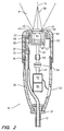
- Figure 2 shows a cross-sectional view of the handheld transthoracic ultrasound transducer of Figure 1.
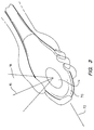
- Figure 3 shows a perspective view of a handheld abdominal ultrasound transducer that is constructed in accordance with a second embodiment of the present invention.
- FIG. 1 shows a perspective view of a handheld transthoracic ultrasound transducer 10 that is constructed in accordance with a first embodiment of the present invention.
- the ultrasound transducer 10 is connected to a remote ultrasound imaging system (not shown) by a transducer cable 12.
- a housing 25 is placed in contact with a patient's skin 13 and a reference axis 15 is coaxial with a longitudinal axis 27 (shown schematically) of the housing.
- the reference axis 15 is aimed at an internal body structure 17.
- the ultrasound transducer 10 forms an ultrasound beam defining an image plane 18 which contains the reference axis 15.
- a two-dimensional (2-d) image of the internal body structure 17 intercepted by the image plane 18 may be observed on the remote ultrasound imaging system.
- a sequence of 2-d images of internal body structures is needed by the physician in order to make a diagnosis. If the image plane 18 is rotated about the reference axis 15 to a second position, a second 2-d view of the internal body structure can be obtained. Similarly, a sequence of 2-d images at predetermined rotational positions may provide the physician with enough information to construct a three-dimensional mental image of the internal body structure 17.
- a sequence of two-dimensional images in which each image is acquired at a known rotational position relative to the reference axis 15 provides spatial correlation needed to mathematically construct a three-dimensional (3-d) image.
- the handheld transthoracic ultrasound transducer provides excellent views of the heart in 2-d cardiac imaging. Because the housing 25 is held stationary relative to the patient, the physician may easily aim the reference axis 15 at the internal body structure 17 of interest and readily control the rotational orientation of the image plane 18 by activating a switch 23 located on the housing 25. Alternatively, the rotational position of the image plane 18 can be electronically controlled through the transducer cable 12 by a pre-programmed sequence generated within the remote ultrasound imaging system or by user controls on the remote ultrasound imaging system.
- the handheld transthoracic ultrasound transducer 10 is axis-symmetrical relative to the reference axis 15 at the surface of contact with the patient's skin 13. This enables the physician to aim the reference axis 15 through the ribs to view the heart equally unobstructed, regardless of the rotational orientation of the housing 25.
- FIG. 2 shows a cross-sectional view of the handheld transthoracic ultrasound transducer 10.
- the transducer cable 12 is connected at a distal end to a remote ultrasound imaging system (not shown) and enters the interior of the housing 25 through a strain-relief fitting 31.
- the proximal end of the transducer cable 12 terminates at an interconnection point 33 at which electrical conductors 35 within the transducer cable connect to a flexible circuit 37.
- the flexible circuit provides electrical connections to a sensor array 50.
- a transmitted electrical signal (not shown) is generated within the remote ultrasound imaging system and propagates through the transducer cable 12 and flexible circuit 37 to the sensor array 50.
- the sensor array converts the electrical signal into an ultrasound beam 39 shown schematically.
- the direction of ultrasound beam may be steered back and forth within the image plane 18 by progressively delaying an electrical signal applied to separate array elements (not shown) within the sensor array 50.
- the image plane 18 in this embodiment is perpendicular to the sensor array 50 and contains the reference axis 15.
- the ultrasound beam 39 propagates from the sensor array 50 and through an acoustic coupling fluid 40 and an acoustic window 42.
- the acoustic window is placed in contact with the patient's skin and the fluid 40 provides an acoustical impedance match between the sensor array 50 and the acoustic window 42 to minimize reflections of the ultrasound beam between the patient and the array sensor 50.
- the ultrasound beam 39 then propagates into the internal body structures where it is attenuated and reflected by internal organs and tissue.
- the reflected ultrasound beam is then received by the sensor array 50 and converted back into a received electrical signal (not shown) which propagates via the transducer cable 12 back to the remote ultrasound imaging system.
- the received electrical signal is then analyzed by the remote ultrasound imaging system to generate a 2-d image of the internal body structure within the image plane 18.
- the sensor array 50 is mounted on top of an acoustic backing 45 which absorbs any backward-travelling ultrasound energy emitted by the sensor array 50.
- the acoustic backing 45 also provides mechanical support for the sensor array 50.
- a thermal conduction path for the sensor array 50 is provided by a heat sink 44 internal to the acoustic backing 45.
- the heat sink 44 is positioned far enough away from the sensor array 50, so that it will not cause acoustic reverberation and degrade the 2-d image quality.
- the acoustic backing 45 and heat sink 44 are mounted on a wave breaker 47 constructed from a composite of materials having significantly differing acoustic impedances and is designed to absorb ultrasound energy.
- the wave breaker 47 is also thermally conductive.
- the wave breaker 47, acoustic backing 45 and sensor array 50 are mounted on a turntable 46 connected to a drive shaft 48 which is rotated by an electric motor 56 located within the housing 25.
- a flexible coupling 52 provides rotational coupling between the electric motor 56 and the drive shaft 48.
- a speed reducing assembly 54 matches the speed and torque of the electric motor 56 to the load of the turntable 46.
- Rotational position can be measured using a position sensing encoder 66 such as a resistive potentiometer and communicated through the transducer cable 12 to the remote ultrasound imaging system.
- Switch 23 may be located on the housing 25 to actuate the rotation of the turntable 46 and sensor array 50 about the reference axis 15.
- the 2-d image plane 18 defined by the electronically steered ultrasound beam 39 may be rotated by rotating the sensor array 50.
- the rotation of the sensor array 50, wave breaker 47 and turntable 46 is facilitated by a set of bearings 57 located in a channel 58 defined by a retaining wall 60 continuous with the turntable 46 and a bearing housing 62 in contact with a window mount 64.
- the acoustic window 42 is stationary within the window mount 64 which is attached to the housing 25.
- the acoustic window 42 may be fabricated from polyester, Mylar or another similar thin shell material, attached to the bearing housing 62 by epoxy or similar adhesive.
- the acoustic window 42 acts as a stationary interface between the patient and sensor array 50. The sensor array 50 can then rotate while the acoustic window 42 does not move relative to the patient's skin.
- the acoustic coupling fluid 40 located between the acoustic window 42 and the sensor array 50 is a layer of flourosilicone, silicone or other similar oil held in place by the surface tension between the two.
- the acoustic coupling fluid 40 has low attenuation to the ultrasound beam 39 and provides rotational coupling between the rotating sensor array 50 and the stationary acoustic window 40.
- FIG. 3 shows a perspective view of a handheld abdominal ultrasound transducer 70 that is constructed in accordance with a second embodiment of the present invention.
- the reference axis 15 and image plane 18 are orthogonal to a longitudinal axis 72 (shown schematically) of the abdominal ultrasound transducer 70.
- This abdominal ultrasound transducer 70 can be positioned with a stationary acoustic window 74 placed on the abdomen of a patient to obtain soft tissue images of the organs in the abdomen or to monitor pregnancies.
- the image plane 18 can be rotated about the reference axis 15 to obtain a sequence of 2-d images.
- the abdominal ultrasound transducer 70 has a sensor array (not shown) that electronically directs an ultrasound beam back and forth within the image plane 18 and then mechanically rotates a sensor array (not shown) behind the stationary acoustic window 74 and a acoustic coupling fluid (not shown). Because there is no relative motion between the stationary acoustic window 74 and the patient's skin, a sequence of 2-d images rotated about the reference axis 15 of the abdomen can be easily obtained.
Landscapes
- Health & Medical Sciences (AREA)
- Life Sciences & Earth Sciences (AREA)
- Physics & Mathematics (AREA)
- Surgery (AREA)
- General Health & Medical Sciences (AREA)
- Pathology (AREA)
- Radiology & Medical Imaging (AREA)
- Engineering & Computer Science (AREA)
- Biomedical Technology (AREA)
- Heart & Thoracic Surgery (AREA)
- Medical Informatics (AREA)
- Molecular Biology (AREA)
- Biophysics (AREA)
- Animal Behavior & Ethology (AREA)
- Nuclear Medicine, Radiotherapy & Molecular Imaging (AREA)
- Public Health (AREA)
- Veterinary Medicine (AREA)
- Acoustics & Sound (AREA)
- Gynecology & Obstetrics (AREA)
- Pregnancy & Childbirth (AREA)
- Ultra Sonic Daignosis Equipment (AREA)
- Transducers For Ultrasonic Waves (AREA)
- Measurement Of Velocity Or Position Using Acoustic Or Ultrasonic Waves (AREA)
- Investigating Or Analyzing Materials By The Use Of Ultrasonic Waves (AREA)
Applications Claiming Priority (2)
| Application Number | Priority Date | Filing Date | Title |
|---|---|---|---|
| US49457695A | 1995-06-22 | 1995-06-22 | |
| US494576 | 1995-06-22 |
Publications (2)
| Publication Number | Publication Date |
|---|---|
| EP0749722A2 true EP0749722A2 (de) | 1996-12-27 |
| EP0749722A3 EP0749722A3 (de) | 1997-04-16 |
Family
ID=23965042
Family Applications (1)
| Application Number | Title | Priority Date | Filing Date |
|---|---|---|---|
| EP96106039A Withdrawn EP0749722A3 (de) | 1995-06-22 | 1996-04-17 | Tragbarer Dreh-Ultraschall-Wandler |
Country Status (2)
| Country | Link |
|---|---|
| EP (1) | EP0749722A3 (de) |
| JP (1) | JPH0919431A (de) |
Cited By (10)
| Publication number | Priority date | Publication date | Assignee | Title |
|---|---|---|---|---|
| EP0927539A1 (de) * | 1997-12-16 | 1999-07-07 | Medison Co., Ltd. | Ultraschall-Handsonde |
| US6194814B1 (en) | 1998-06-08 | 2001-02-27 | Acuson Corporation | Nosepiece having an integrated faceplate window for phased-array acoustic transducers |
| GB2408575A (en) * | 2003-11-26 | 2005-06-01 | Ge Med Sys Global Tech Co Llc | Moulded enclosure for ultrasound probe with soft plastic component for contact with patients body |
| CN100446731C (zh) * | 2004-07-28 | 2008-12-31 | 松下电器产业株式会社 | 超声波探头 |
| CN102247161A (zh) * | 2011-04-07 | 2011-11-23 | 楼震 | 一种新型动物用b超探头 |
| WO2014053958A1 (en) * | 2012-10-02 | 2014-04-10 | Koninklijke Philips N.V. | Tool for opening and closing a transducer housing |
| WO2017106748A1 (en) * | 2015-12-16 | 2017-06-22 | Glo-Tip, Llc | Needle tracking transducer array methods and apparatus |
| CN108013899A (zh) * | 2016-11-04 | 2018-05-11 | 通用电气公司 | 用于医学成像系统的方法和系统 |
| US10945706B2 (en) | 2017-05-05 | 2021-03-16 | Biim Ultrasound As | Hand held ultrasound probe |
| AU2023379184B2 (en) * | 2022-11-11 | 2026-05-07 | Classys Inc. | Therapeutic ultrasound generation device, and handpiece for ultrasound treatment including same |
Family Cites Families (4)
| Publication number | Priority date | Publication date | Assignee | Title |
|---|---|---|---|---|
| EP0359546B1 (de) * | 1988-09-16 | 1993-08-11 | Hewlett-Packard Company | Ultraschallanordnung mit verbesserter Kopplungsflüssigkeit |
| US5159931A (en) * | 1988-11-25 | 1992-11-03 | Riccardo Pini | Apparatus for obtaining a three-dimensional reconstruction of anatomic structures through the acquisition of echographic images |
| EP0509296B1 (de) * | 1991-04-16 | 1996-09-04 | Hewlett-Packard Company | Endoskopischer Ultraschallkopf mit Kabelaufrollmechanismus |
| US5181514A (en) * | 1991-05-21 | 1993-01-26 | Hewlett-Packard Company | Transducer positioning system |
-
1996
- 1996-04-17 EP EP96106039A patent/EP0749722A3/de not_active Withdrawn
- 1996-06-19 JP JP8158210A patent/JPH0919431A/ja active Pending
Cited By (17)
| Publication number | Priority date | Publication date | Assignee | Title |
|---|---|---|---|---|
| EP0927539A1 (de) * | 1997-12-16 | 1999-07-07 | Medison Co., Ltd. | Ultraschall-Handsonde |
| US6194814B1 (en) | 1998-06-08 | 2001-02-27 | Acuson Corporation | Nosepiece having an integrated faceplate window for phased-array acoustic transducers |
| GB2408575A (en) * | 2003-11-26 | 2005-06-01 | Ge Med Sys Global Tech Co Llc | Moulded enclosure for ultrasound probe with soft plastic component for contact with patients body |
| GB2408575B (en) * | 2003-11-26 | 2006-09-20 | Ge Med Sys Global Tech Co Llc | Ultrasonic probe |
| CN100446731C (zh) * | 2004-07-28 | 2008-12-31 | 松下电器产业株式会社 | 超声波探头 |
| US7798969B2 (en) | 2004-07-28 | 2010-09-21 | Panasonic Corporation | Ultrasonic probe |
| CN102247161A (zh) * | 2011-04-07 | 2011-11-23 | 楼震 | 一种新型动物用b超探头 |
| CN104703545A (zh) * | 2012-10-02 | 2015-06-10 | 皇家飞利浦有限公司 | 用于打开和闭合换能器壳体的工具 |
| WO2014053958A1 (en) * | 2012-10-02 | 2014-04-10 | Koninklijke Philips N.V. | Tool for opening and closing a transducer housing |
| CN104703545B (zh) * | 2012-10-02 | 2017-06-20 | 皇家飞利浦有限公司 | 用于打开和闭合换能器壳体的工具 |
| US9743907B2 (en) | 2012-10-02 | 2017-08-29 | Koninklijke Philips N.V. | Tool for opening and closing a transducer housing |
| WO2017106748A1 (en) * | 2015-12-16 | 2017-06-22 | Glo-Tip, Llc | Needle tracking transducer array methods and apparatus |
| CN108013899A (zh) * | 2016-11-04 | 2018-05-11 | 通用电气公司 | 用于医学成像系统的方法和系统 |
| CN108013899B (zh) * | 2016-11-04 | 2021-05-28 | 通用电气公司 | 用于医学成像系统的方法和系统 |
| US10945706B2 (en) | 2017-05-05 | 2021-03-16 | Biim Ultrasound As | Hand held ultrasound probe |
| US11744551B2 (en) | 2017-05-05 | 2023-09-05 | Biim Ultrasound As | Hand held ultrasound probe |
| AU2023379184B2 (en) * | 2022-11-11 | 2026-05-07 | Classys Inc. | Therapeutic ultrasound generation device, and handpiece for ultrasound treatment including same |
Also Published As
| Publication number | Publication date |
|---|---|
| EP0749722A3 (de) | 1997-04-16 |
| JPH0919431A (ja) | 1997-01-21 |
Similar Documents
| Publication | Publication Date | Title |
|---|---|---|
| JP2715762B2 (ja) | 超音波検査装置 | |
| US4543960A (en) | Transesophageal echo cardiography scanhead | |
| US5598846A (en) | Rotatable ultrasound transducer finger probe | |
| US5575288A (en) | Compact rotationally steerable ultrasound transducer | |
| CA1304493C (en) | Endoscopically deliverable ultrasound imaging system | |
| EP2648624B1 (de) | Bildgebungswandlersonde | |
| US4601292A (en) | Steerable Doppler transducer probes | |
| US8568324B2 (en) | Systems and methods for mechanical translation of full matrix array | |
| JPH0919431A (ja) | 超音波トランスデューサ | |
| JP2001120550A (ja) | 体腔内超音波プローブシステム | |
| US5494040A (en) | Ultrasonic diagnosis device with bright position-indicating line | |
| JP7403358B2 (ja) | 超音波探触子 | |
| JPS63115546A (ja) | 超音波探触子 | |
| JPH05344974A (ja) | 超音波探触子 | |
| US20070232921A1 (en) | Transducer assembly having a wide field of view | |
| JP3905585B2 (ja) | 経食道超音波プローブ | |
| JPH049149A (ja) | 三次元データ取込み用超音波探触子 | |
| JPH114827A (ja) | 体腔内超音波診断装置 | |
| US12490956B2 (en) | Robot-assisted tele-echography probe | |
| JP3304711B2 (ja) | 超音波プローブ | |
| JP3852296B2 (ja) | 超音波プローブ | |
| JPH031850A (ja) | 体腔内超音波探触子 | |
| JPH11332867A (ja) | 超音波内視鏡装置 | |
| JP3198903B2 (ja) | 超音波診断装置 | |
| JP2712975B2 (ja) | 体腔内用超音波プローブ |
Legal Events
| Date | Code | Title | Description |
|---|---|---|---|
| PUAI | Public reference made under article 153(3) epc to a published international application that has entered the european phase |
Free format text: ORIGINAL CODE: 0009012 |
|
| AK | Designated contracting states |
Kind code of ref document: A2 Designated state(s): DE GB NL |
|
| PUAL | Search report despatched |
Free format text: ORIGINAL CODE: 0009013 |
|
| STAA | Information on the status of an ep patent application or granted ep patent |
Free format text: STATUS: THE APPLICATION HAS BEEN WITHDRAWN |
|
| AK | Designated contracting states |
Kind code of ref document: A3 Designated state(s): DE GB NL |
|
| 18W | Application withdrawn |
Withdrawal date: 19970326 |