EP0749765B1 - Bindungssystem für Schuhe auf Skiern - Google Patents
Bindungssystem für Schuhe auf Skiern Download PDFInfo
- Publication number
- EP0749765B1 EP0749765B1 EP96107731A EP96107731A EP0749765B1 EP 0749765 B1 EP0749765 B1 EP 0749765B1 EP 96107731 A EP96107731 A EP 96107731A EP 96107731 A EP96107731 A EP 96107731A EP 0749765 B1 EP0749765 B1 EP 0749765B1
- Authority
- EP
- European Patent Office
- Prior art keywords
- fact
- lock
- set forth
- lever
- height
- Prior art date
- Legal status (The legal status is an assumption and is not a legal conclusion. Google has not performed a legal analysis and makes no representation as to the accuracy of the status listed.)
- Expired - Lifetime
Links
- 210000003811 finger Anatomy 0.000 description 7
- 210000003813 thumb Anatomy 0.000 description 5
- 230000035939 shock Effects 0.000 description 4
- 229920001971 elastomer Polymers 0.000 description 3
- 239000000806 elastomer Substances 0.000 description 3
- 210000000056 organ Anatomy 0.000 description 3
- 238000006073 displacement reaction Methods 0.000 description 2
- 230000000694 effects Effects 0.000 description 2
- 239000000463 material Substances 0.000 description 2
- 230000002747 voluntary effect Effects 0.000 description 2
- 230000006835 compression Effects 0.000 description 1
- 238000007906 compression Methods 0.000 description 1
- 230000014759 maintenance of location Effects 0.000 description 1
- 238000004519 manufacturing process Methods 0.000 description 1
- 238000000465 moulding Methods 0.000 description 1
- 230000002028 premature Effects 0.000 description 1
- 230000000717 retained effect Effects 0.000 description 1
- 238000004073 vulcanization Methods 0.000 description 1
Images

Classifications
-
- A—HUMAN NECESSITIES
- A63—SPORTS; GAMES; AMUSEMENTS
- A63C—SKATES; SKIS; ROLLER SKATES; DESIGN OR LAYOUT OF COURTS, RINKS OR THE LIKE
- A63C9/00—Ski bindings
- A63C9/005—Ski bindings with means for adjusting the position of a shoe holder or of the complete binding relative to the ski
Definitions
- the invention relates to a shoe retaining element on a sliding board, including a ski. More specifically, the invention relates to the position adjustment device longitudinal of a retaining element on a ski.
- each element has a jaw carried by. a body which is mobile under the effect of the shoe stresses against the restoring force a spring housed in the body.
- the body of the rear element is, in known manner, movable along a slide, and a lock allows the body to be positioned in a precise position adapted to the length of the shoe. From this position defined by the lock, the body can still slide towards the rear, when the boot is engaged and during ski flexions, against the restoring force one or more springs called recoil springs It also happens that the retaining element front has a movable body along a slide.
- the recoil spring (s) determine the thrust that the retaining element applies to the boot, the front element forming a fixed stop on the ski.
- the thrust depends on the longitudinal position of the body along the slide. A position rear element too far back gives too little thrust, resulting in loose support the boot in the retaining elements, great imprecision in the handling of the ski, and a high risk of untimely triggering by premature release of the shoe. A initial position of the rear element too advanced makes it difficult to put on. The push is too strong and disturbs the correct functioning of the retaining elements.
- Adjustment of the longitudinal position of the retaining elements, in particular of the element rear, is an important operation on which the proper functioning of the elements depends. A some experience is necessary to perform this operation, because it must be checked that the thrust is within a correct value range. A ski specialist can do this operation without difficulty, but, as a rule, the ski user is not able to perform the adjustment itself, or to find a good adjustment after an accidental displacement of item.
- the lock which allows this longitudinal adjustment must be accessible and easy to maneuver. Once the lock is in the open position, the body of the element can be easily manipulated to bring it into a new position. This is particularly important for skis used for rental where adjustment is necessary for each new user.
- the lock With respect to the user, the lock must be well protected to prevent it from opening accidentally, for example, while skiing, following blows from from the other ski during a fall, or from the skis of other skiers in the queues to the lifts. It is also necessary to prevent the lock from accidentally opening during transport and handling of skis.
- a lock, as described in German patent application DE 27 47 626 is easy to maneuver but poorly protected. Indeed, given its dimensions and its orientation, the long operating tab can be very easily lifted accidental, for example when handling skis.
- a lock such as that described in patent application FR 2 672 506 offers a good compromise between good protection for the user and ease of operation for the specialist.
- the body is easy to move for the specialist. Indeed, by placing by example the thumb on the body of the element, and by raising the loop with the index finger, the specialist has a good grip for easily moving the body to its new position.
- Such a lock is however complex to carry out on a mechanical level, because it requires several pieces of link to access the lock itself.
- An object of the invention is to improve the existing adjustment devices, and to achieve a longitudinal adjustment device which gives a very good compromise between the ease of manufacturing for the manufacturer, accessibility and ease of handling for the specialist, and protection against accidental opening for the user.
- the invention proposes to achieve this goal by extending the horizontal part of the latch by a flexible operating member extending along the rear face of the body the retaining element, and having the overall shape of a "T", including the branches of the bar horizontal top are intended to be lifted by two fingers of the hand.
- the operating member is produced in a flexible material.
- the base of the operating member has a ramp oriented from bottom to top and back to front.
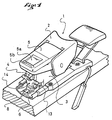
- FIG. 1 is a perspective view of a rear retaining element fitted with the longitudinal adjustment device of the invention.
- Figure 2 shows in side view and in partial section the rear part of the element Figure 1.
- Figure 3 is a front view of the actuator which equips the device Figures 1 and 2.
- FIG. 1 represents a rear retaining element 1.
- the element has a jaw 2 carried by a body 3.
- the jaw is movable around an axis transverse carried by the body, and its movement is controlled by a spring housed in the body.
- the initial compression of the spring is adjustable by a plug 4 accessible on the rear face of the body. The plug is located about halfway up the body.
- the jaw has two stable equilibrium positions, one low shoe retention position, and a high shoe release position.
- the Figure 1 shows the retaining element with the jaw in the high position.
- a lever of heaving 5 allows the jaw to be brought up by a voluntary action.
- the lever 5 is articulated to the body in the vicinity of the axis of rotation of the jaw.
- the release lever is lying on the back of the body. In this position, the rear end of the lever 5 extends a little beyond the body.
- This rear end preferably has a bowl 5a in which the end of the stick can be engaged, and a protruding rim 5b.
- the body 3 is slidably mounted along a slide 6 which is intended to be secured to a ski.
- the position of the body along the slide is defined by adjustment means longitudinal.
- the slide has an elevated central portion pierced with a plurality of orifices 8.
- the body 3 has in its lower part, on the rear, a lock 9 provided with teeth 10 which are intended to engage in one or more orifices neighboring the slide.
- the lock 9 is slidably mounted inside the body, and a recoil spring 12 housed in the rear part of the body pushes the latch into abutment towards the rear of the body.
- the recoil spring 12 defines the thrust that the retaining element exerts on the shoe.
- the recoil spring also ensures the return of the lock in its locked position, i.e. its low position where its teeth are engaged in holes. From this position, the lock can be raised until the teeth are free from the orifices of the slide. In this case, it is not intended that the upper position of the lock is a stable position. But, as will appear later, the invention could be applied to locks with two stable positions.
- the latch has an operating tab 13 towards the rear.
- the rear end of the tongue is extended upwards by an operating member 14.
- the actuator 14 extends upward along the rear face of the body. Seen from face, it generally has the shape of a "T”, with a central upright 15 and a bar transverse upper 16. The organ is located substantially perpendicular to the rear end of the heaving lever, when the lever is lying alongside the body.
- the operating member is intended to be used in the following manner. Generally, the adjustment in longitudinal position of the body is carried out while the jaw is in position open, and the release lever is in the supine position. In addition, for such an adjustment, the specialist is used to presenting the skis flat, facing him, with the spatula to his left, and the heel to his right.
- the lock can be brought to the lower position very simple way by placing your thumb in the middle of the crossbar 16 and then exerting a push down on this bar. This movement is also achievable very natural.
- the height dimension of the operating member is determined so that in position high of the lock, the crossbar does not come up against the rear end of the lever and let her stay underneath.
- the operating member has in its conditions a similar height half the height of the body.
- the member has a central clearance 17 in the middle of the crossbar 16. This clearance is provided so that the plug 4 remains accessible.
- the upright 15 has a substantially rectangular section, the largest of which dimension corresponds substantially to the width of the lock.
- the crossbar has an approximately circular section, at less at the end of its branches.
- the branches of the bar 16 extend from each side of the upright 15 over a distance corresponding approximately to half the width of the index or middle finger of a human being about 10 millimeters, and the branches are connected to the upright by a quarter-circle rib whose curvature is approximately that of the tip of the index or middle finger.
- These shapes and dimensions are intended to facilitate the grip of the operating member. But they are not limiting for the invention, and any other suitable shape or size is suitable.
- the operating member is flexible, that is to say it is produced by example in deformable plastic, or elastomer.
- the rigidity of the organ of maneuver is however sufficient for the operating member to stand on its own erected along the back of the body.
- the lock itself is made of a material rigid in view of its function, the operating member is assembled to the bolt by any appropriate means.
- the member 14 extends forward by a tab 19 which passes under the rear end of the lock, and which is assembled to this end for example by screws or rivets. Any other means of mechanical assembly, for example bonding or other is also suitable.
- the lock is metallic and the operating member is made in a vulcanizable elastomer, the operating member can be produced by counter-molding on the end of the lock. The assembly occurs by itself with the vulcanization of the elastomer.
- the flexibility of the operating member makes the device and the body of the element restraint less sensitive to shocks. In fact, in the event of impact, the operating member deforms and is pressed against the rear face of the body which it also protects. The operating device also absorbs each shock by its deformation.
- the amount of the operating member has at its base a ramp inclined from bottom to top and back to front. Thanks to this ramp, the shocks applied to the base of the actuator produce in the lock a downward component. This component opposes the opening of the lock. In addition, the deformation of the organ of maneuver under the effect of the shock increases the slope of the ramp 20 in the direction where it prevents opening the lock.
- the operating member which has just been described facilitates the operation of the lock. He makes it also safer insofar as the operation of the bolt and the longitudinal displacement of the bodies are easy and natural only if the ski is facing the manipulator, with the spatula left and heel on the right. In other cases, either the opening of the lock, or the moving the body requires significant voluntary effort.
- the latch does not lift easily unless the two branches of the crossbar 16 are stressed simultaneously. If one of the branches only is grasped, the operating member responds with a deformation in the advantageous case where it is flexible.
- the device which has just been described can be produced in a very simple manner. It does require no particular arrangement of the body of the retaining element, apart from the bolt itself, more precisely the rear end of the lock.
- the lock itself is well protected against openings accidental, notably because of its flexibility and the ramp it presents at the base of the amount.
- the invention is not limited to a rear retaining element. She could also apply to a front retainer which would have a movable body along a slide. In this case, the device could be located on the front or on the side of the body.
Landscapes
- Footwear And Its Accessory, Manufacturing Method And Apparatuses (AREA)
Claims (7)
- Halteelement eines Schuhs auf einem Gleitbrett, umfassend einen Körper (3), beweglich entlang einer Gleitschiene (6), einen Riegel (9), welcher durch den Körper getragen wird zum Feststellen des Körpers entlang der Gleitschiene in einer definierten Position, dadurch gekennzeichnet, dass der Riegel verlängert ist durch ein Handhabungsorgan (14), welches flexibel ist und welches sich in Richtung nach oben entlang der hinteren Seite des Körpers erstreckt auf eine Höhe in der Nähe der Mitte von der Höhe des Körpers, und dass das Handhabungsorgan eine "T"-Form aufweist, mit einem zentralen aufsteigenden Abschnitt (15), der überragt wird von einem transversalen Stab (16), dessen Höhe und Länge auf jeder Seite des aufsteigenden Abschnitts vorgesehen sind, um den Eingriff von Fingern einer Hand zu ermöglichen.
- Element gemäß Anspruch 1, dadurch gekennzeichnet, dass die äußere Seite des aufsteigenden Abschnitts in ihrem unteren Teil eine Rampe (20) aufweist, die in solch einer Weise orientiert ist, dass eine angewendete Kraft auf die Rampe eine Komponente aufweist, die in Richtung nach unten orientiert ist.
- Element gemäß Anspruch 1, dadurch gekennzeichnet, dass der transversale Stab (16) rotationszylindrische Enden aufweist.
- Element gemäß Anspruch 1, dadurch gekennzeichnet, dass der Querstab an dem aufsteigenden Abschnitt verbunden ist durch kreisbogenförmige Rippen.
- Halteelement gemäß Anspruch 1 des hinteren Typs, aufweisend eine Klemmbacke (2), die durch den Körper (3) getragen ist, einen Öffnungshebel (5) der mobilen Klemmbacke zwischen einer oberen Position und einer unteren Position, wo der Hebel entlang dem Körper (3) angelegt ist, und wo sein Ende sich über die hintere Seite des Körpers erstreckt, dadurch gekennzeichnet, dass der Handhabungshebel sich in Richtung nach oben erstreckt, im Wesentlichen senkrecht zum hinteren Ende des Öffnungshebels, wenn dieser in einer angelegten Position ist.
- Element nach Anspruch 5, dadurch gekennzeichnet, dass das Handhabungsorgan sich in etwa bis zur Hälfte der Höhe der hinteren Seite des Körpers (3) erstreckt.
- Element nach Anspruch 6, dadurch gekennzeichnet, dass das Handhabungsorgan eine Aussparung (17) in dem zentralen Teil des transversalen Stabes (16) aufweist.
Applications Claiming Priority (2)
| Application Number | Priority Date | Filing Date | Title |
|---|---|---|---|
| FR9507694 | 1995-06-22 | ||
| FR9507694A FR2735699B1 (fr) | 1995-06-22 | 1995-06-22 | Element de retenue d'une chaussure sur un ski |
Publications (2)
| Publication Number | Publication Date |
|---|---|
| EP0749765A1 EP0749765A1 (de) | 1996-12-27 |
| EP0749765B1 true EP0749765B1 (de) | 2002-01-30 |
Family
ID=9480418
Family Applications (1)
| Application Number | Title | Priority Date | Filing Date |
|---|---|---|---|
| EP96107731A Expired - Lifetime EP0749765B1 (de) | 1995-06-22 | 1996-05-15 | Bindungssystem für Schuhe auf Skiern |
Country Status (6)
| Country | Link |
|---|---|
| US (1) | US5813690A (de) |
| EP (1) | EP0749765B1 (de) |
| JP (1) | JPH0910374A (de) |
| AT (1) | ATE212557T1 (de) |
| DE (1) | DE69618858T2 (de) |
| FR (1) | FR2735699B1 (de) |
Families Citing this family (4)
| Publication number | Priority date | Publication date | Assignee | Title |
|---|---|---|---|---|
| FR2769237B1 (fr) * | 1997-10-06 | 1999-12-10 | Rossignol Sa | Dispositif de retenue d'une chaussure sur une planche de glisse, en particulier un ski |
| US6659494B1 (en) * | 2000-08-10 | 2003-12-09 | Ralph M. Martin | Backwards release ski binding on a pivot plate mount |
| US6769711B1 (en) | 2000-08-10 | 2004-08-03 | Ralph M. Martin | Gas powered backwards release ski binding |
| CA2513014A1 (en) * | 2005-07-22 | 2007-01-22 | Research In Motion Limited | A method of controlling delivery of multi-part content from an origin server to a mobile device browser via a proxy server |
Family Cites Families (10)
| Publication number | Priority date | Publication date | Assignee | Title |
|---|---|---|---|---|
| FR2368974A1 (fr) * | 1976-11-02 | 1978-05-26 | Beyl Jean Joseph Alfred | Dispositif de fixation de ski |
| FR2451756A1 (fr) * | 1979-03-19 | 1980-10-17 | Salomon & Fils F | Fixation de securite pour ski |
| EP0098515B1 (de) * | 1982-07-05 | 1985-09-18 | Tmc Corporation | Vorrichtung zur Längsverstellung von Skibindungsteilen |
| AT377701B (de) * | 1983-03-04 | 1985-04-25 | Tyrolia Freizeitgeraete | Vorrichtung zur laengsverstellung |
| AT383039B (de) * | 1984-07-12 | 1987-05-11 | Amf Sport Freizeitgeraete | Vorrichtung zur laengsverstellung von skibindungs- teilen |
| AT387150B (de) * | 1984-07-12 | 1988-12-12 | Amf Sport Freizeitgeraete | Fersenniederhalter |
| FR2614545B1 (fr) * | 1987-04-30 | 1989-06-16 | Salomon Sa | Fixation de securite pour ski |
| FR2647357B1 (fr) * | 1989-05-26 | 1991-09-13 | Salomon Sa | Fixation de securite pour ski |
| FR2672506B1 (fr) * | 1991-02-08 | 1993-04-30 | Salomon Sa | Fixation de securite pour ski. |
| FR2684889B1 (fr) * | 1991-12-13 | 1994-02-04 | Salomon Sa | Piece d'interface pour la glissiere d'un element de fixation, notamment de fixation alpine. |
-
1995
- 1995-06-22 FR FR9507694A patent/FR2735699B1/fr not_active Expired - Fee Related
-
1996
- 1996-05-15 DE DE69618858T patent/DE69618858T2/de not_active Expired - Fee Related
- 1996-05-15 EP EP96107731A patent/EP0749765B1/de not_active Expired - Lifetime
- 1996-05-15 AT AT96107731T patent/ATE212557T1/de not_active IP Right Cessation
- 1996-06-19 US US08/667,035 patent/US5813690A/en not_active Expired - Fee Related
- 1996-06-20 JP JP8158737A patent/JPH0910374A/ja active Pending
Also Published As
| Publication number | Publication date |
|---|---|
| ATE212557T1 (de) | 2002-02-15 |
| JPH0910374A (ja) | 1997-01-14 |
| FR2735699B1 (fr) | 1997-09-05 |
| FR2735699A1 (fr) | 1996-12-27 |
| DE69618858T2 (de) | 2002-09-05 |
| DE69618858D1 (de) | 2002-03-14 |
| US5813690A (en) | 1998-09-29 |
| EP0749765A1 (de) | 1996-12-27 |
Similar Documents
| Publication | Publication Date | Title |
|---|---|---|
| EP0086908B1 (de) | Skischuh | |
| EP0169080B1 (de) | Befestigungsvorrichtung für einen Schuh an einem Pedal, Schuh und Pedal ausgestattet mit dieser Vorrichtung | |
| EP0650385B1 (de) | Rückhaltevorrichtung für einen snowboardschuh | |
| EP0679415B1 (de) | Vorrichtung zum Befestigen eines Schuhs an einem Gleitorgan | |
| FR2472920A2 (fr) | Chaussure de sport a haut de tige dynamique reglable | |
| FR2752528A1 (fr) | Dispositif de fixation du pied sur un engin de sport, du type planche de surf des neiges, planche ou patin a roulettes, compose d'une botte et d'une embase fixee a l'engin de sport | |
| FR2882658A1 (fr) | Dispositif de fixation a double commande | |
| EP2399654A1 (de) | Sicherheitsbefestigung für den Skitourensport | |
| EP0620711B1 (de) | Langlaufschischuh und kombination von schi, bindung und schuh | |
| FR2741543A1 (fr) | Fixations pour ski de fond | |
| EP1935461B1 (de) | Mit einem mindestens zwischen zwei Positionen hin und her schaltbaren, beweglichen Knopf ausgestatteter Artikel | |
| EP3437703B1 (de) | Bremsvorrichtung für tourenski | |
| EP0749765B1 (de) | Bindungssystem für Schuhe auf Skiern | |
| EP3827887B1 (de) | Hinterbacken für tourenskier | |
| EP0193686B1 (de) | Rückhaltevorrichtung für einen Schuh auf einem Ski | |
| EP1813321B1 (de) | Befestigungsschlinge mit Element zum sicheren Anlegen | |
| EP0778056B1 (de) | Schuhrückhaltevorrichtung auf einem Snowboard bzw. Ski oder ähnlichem | |
| EP1027908A1 (de) | Rückhaltesystem für Schuhe auf Skier | |
| EP0739646B1 (de) | Bindungssystem für Schuhe auf Skiern | |
| EP1785172B1 (de) | Sportschuh-Bindungsvorrichtung auf einem Gleitbrett | |
| FR2607712A1 (fr) | Frein de ski | |
| EP2322255A1 (de) | Bremsvorrichtung für Snowboard | |
| EP0761114B1 (de) | Skischuh | |
| WO1996004049A1 (fr) | Fixations de raquettes a neige | |
| FR3141075A1 (fr) | Dispositif de freinage pour une planche de glisse |
Legal Events
| Date | Code | Title | Description |
|---|---|---|---|
| PUAI | Public reference made under article 153(3) epc to a published international application that has entered the european phase |
Free format text: ORIGINAL CODE: 0009012 |
|
| AK | Designated contracting states |
Kind code of ref document: A1 Designated state(s): AT CH DE IT LI |
|
| 17P | Request for examination filed |
Effective date: 19970618 |
|
| 17Q | First examination report despatched |
Effective date: 19990517 |
|
| GRAG | Despatch of communication of intention to grant |
Free format text: ORIGINAL CODE: EPIDOS AGRA |
|
| GRAG | Despatch of communication of intention to grant |
Free format text: ORIGINAL CODE: EPIDOS AGRA |
|
| GRAH | Despatch of communication of intention to grant a patent |
Free format text: ORIGINAL CODE: EPIDOS IGRA |
|
| GRAH | Despatch of communication of intention to grant a patent |
Free format text: ORIGINAL CODE: EPIDOS IGRA |
|
| GRAA | (expected) grant |
Free format text: ORIGINAL CODE: 0009210 |
|
| AK | Designated contracting states |
Kind code of ref document: B1 Designated state(s): AT CH DE IT LI |
|
| PG25 | Lapsed in a contracting state [announced via postgrant information from national office to epo] |
Ref country code: IT Free format text: LAPSE BECAUSE OF FAILURE TO SUBMIT A TRANSLATION OF THE DESCRIPTION OR TO PAY THE FEE WITHIN THE PRE;WARNING: LAPSES OF ITALIAN PATENTS WITH EFFECTIVE DATE BEFORE 2007 MAY HAVE OCCURRED AT ANY TIME BEFORE 2007. THE CORRECT EFFECTIVE DATE MAY BE DIFFERENT FROM THE ONE RECORDED.SCRIBED TIME-LIMIT Effective date: 20020130 |
|
| REF | Corresponds to: |
Ref document number: 212557 Country of ref document: AT Date of ref document: 20020215 Kind code of ref document: T |
|
| REG | Reference to a national code |
Ref country code: CH Ref legal event code: EP |
|
| REF | Corresponds to: |
Ref document number: 69618858 Country of ref document: DE Date of ref document: 20020314 |
|
| PG25 | Lapsed in a contracting state [announced via postgrant information from national office to epo] |
Ref country code: LI Free format text: LAPSE BECAUSE OF NON-PAYMENT OF DUE FEES Effective date: 20020531 Ref country code: CH Free format text: LAPSE BECAUSE OF NON-PAYMENT OF DUE FEES Effective date: 20020531 |
|
| PLBE | No opposition filed within time limit |
Free format text: ORIGINAL CODE: 0009261 |
|
| STAA | Information on the status of an ep patent application or granted ep patent |
Free format text: STATUS: NO OPPOSITION FILED WITHIN TIME LIMIT |
|
| REG | Reference to a national code |
Ref country code: CH Ref legal event code: PL |
|
| 26N | No opposition filed | ||
| PGFP | Annual fee paid to national office [announced via postgrant information from national office to epo] |
Ref country code: DE Payment date: 20070510 Year of fee payment: 12 |
|
| PGFP | Annual fee paid to national office [announced via postgrant information from national office to epo] |
Ref country code: AT Payment date: 20070511 Year of fee payment: 12 |
|
| PG25 | Lapsed in a contracting state [announced via postgrant information from national office to epo] |
Ref country code: AT Free format text: LAPSE BECAUSE OF NON-PAYMENT OF DUE FEES Effective date: 20080515 |
|
| PG25 | Lapsed in a contracting state [announced via postgrant information from national office to epo] |
Ref country code: DE Free format text: LAPSE BECAUSE OF NON-PAYMENT OF DUE FEES Effective date: 20081202 |