EP0749824B1 - Pressvorrichtung und Verfahren zur Überlappungsschweissen von thermoplastischen Folien - Google Patents
Pressvorrichtung und Verfahren zur Überlappungsschweissen von thermoplastischen Folien Download PDFInfo
- Publication number
- EP0749824B1 EP0749824B1 EP96630035A EP96630035A EP0749824B1 EP 0749824 B1 EP0749824 B1 EP 0749824B1 EP 96630035 A EP96630035 A EP 96630035A EP 96630035 A EP96630035 A EP 96630035A EP 0749824 B1 EP0749824 B1 EP 0749824B1
- Authority
- EP
- European Patent Office
- Prior art keywords
- workpieces
- platen
- diaphragm
- pressurized fluid
- membranes
- Prior art date
- Legal status (The legal status is an assumption and is not a legal conclusion. Google has not performed a legal analysis and makes no representation as to the accuracy of the status listed.)
- Expired - Lifetime
Links
Images



Classifications
-
- B—PERFORMING OPERATIONS; TRANSPORTING
- B29—WORKING OF PLASTICS; WORKING OF SUBSTANCES IN A PLASTIC STATE IN GENERAL
- B29C—SHAPING OR JOINING OF PLASTICS; SHAPING OF MATERIAL IN A PLASTIC STATE, NOT OTHERWISE PROVIDED FOR; AFTER-TREATMENT OF THE SHAPED PRODUCTS, e.g. REPAIRING
- B29C65/00—Joining or sealing of preformed parts, e.g. welding of plastics materials; Apparatus therefor
- B29C65/02—Joining or sealing of preformed parts, e.g. welding of plastics materials; Apparatus therefor by heating, with or without pressure
- B29C65/18—Joining or sealing of preformed parts, e.g. welding of plastics materials; Apparatus therefor by heating, with or without pressure using heated tools
-
- B—PERFORMING OPERATIONS; TRANSPORTING
- B29—WORKING OF PLASTICS; WORKING OF SUBSTANCES IN A PLASTIC STATE IN GENERAL
- B29C—SHAPING OR JOINING OF PLASTICS; SHAPING OF MATERIAL IN A PLASTIC STATE, NOT OTHERWISE PROVIDED FOR; AFTER-TREATMENT OF THE SHAPED PRODUCTS, e.g. REPAIRING
- B29C66/00—General aspects of processes or apparatus for joining preformed parts
- B29C66/01—General aspects dealing with the joint area or with the area to be joined
- B29C66/03—After-treatments in the joint area
- B29C66/034—Thermal after-treatments
- B29C66/0342—Cooling, e.g. transporting through welding and cooling zone
-
- B—PERFORMING OPERATIONS; TRANSPORTING
- B29—WORKING OF PLASTICS; WORKING OF SUBSTANCES IN A PLASTIC STATE IN GENERAL
- B29C—SHAPING OR JOINING OF PLASTICS; SHAPING OF MATERIAL IN A PLASTIC STATE, NOT OTHERWISE PROVIDED FOR; AFTER-TREATMENT OF THE SHAPED PRODUCTS, e.g. REPAIRING
- B29C66/00—General aspects of processes or apparatus for joining preformed parts
- B29C66/01—General aspects dealing with the joint area or with the area to be joined
- B29C66/05—Particular design of joint configurations
- B29C66/10—Particular design of joint configurations particular design of the joint cross-sections
- B29C66/11—Joint cross-sections comprising a single joint-segment, i.e. one of the parts to be joined comprising a single joint-segment in the joint cross-section
- B29C66/112—Single lapped joints
- B29C66/1122—Single lap to lap joints, i.e. overlap joints
-
- B—PERFORMING OPERATIONS; TRANSPORTING
- B29—WORKING OF PLASTICS; WORKING OF SUBSTANCES IN A PLASTIC STATE IN GENERAL
- B29C—SHAPING OR JOINING OF PLASTICS; SHAPING OF MATERIAL IN A PLASTIC STATE, NOT OTHERWISE PROVIDED FOR; AFTER-TREATMENT OF THE SHAPED PRODUCTS, e.g. REPAIRING
- B29C66/00—General aspects of processes or apparatus for joining preformed parts
- B29C66/40—General aspects of joining substantially flat articles, e.g. plates, sheets or web-like materials; Making flat seams in tubular or hollow articles; Joining single elements to substantially flat surfaces
- B29C66/41—Joining substantially flat articles ; Making flat seams in tubular or hollow articles
- B29C66/43—Joining a relatively small portion of the surface of said articles
-
- B—PERFORMING OPERATIONS; TRANSPORTING
- B29—WORKING OF PLASTICS; WORKING OF SUBSTANCES IN A PLASTIC STATE IN GENERAL
- B29C—SHAPING OR JOINING OF PLASTICS; SHAPING OF MATERIAL IN A PLASTIC STATE, NOT OTHERWISE PROVIDED FOR; AFTER-TREATMENT OF THE SHAPED PRODUCTS, e.g. REPAIRING
- B29C66/00—General aspects of processes or apparatus for joining preformed parts
- B29C66/70—General aspects of processes or apparatus for joining preformed parts characterised by the composition, physical properties or the structure of the material of the parts to be joined; Joining with non-plastics material
- B29C66/73—General aspects of processes or apparatus for joining preformed parts characterised by the composition, physical properties or the structure of the material of the parts to be joined; Joining with non-plastics material characterised by the intensive physical properties of the material of the parts to be joined, by the optical properties of the material of the parts to be joined, by the extensive physical properties of the parts to be joined, by the state of the material of the parts to be joined or by the material of the parts to be joined being a thermoplastic or a thermoset
- B29C66/739—General aspects of processes or apparatus for joining preformed parts characterised by the composition, physical properties or the structure of the material of the parts to be joined; Joining with non-plastics material characterised by the intensive physical properties of the material of the parts to be joined, by the optical properties of the material of the parts to be joined, by the extensive physical properties of the parts to be joined, by the state of the material of the parts to be joined or by the material of the parts to be joined being a thermoplastic or a thermoset characterised by the material of the parts to be joined being a thermoplastic or a thermoset
- B29C66/7392—General aspects of processes or apparatus for joining preformed parts characterised by the composition, physical properties or the structure of the material of the parts to be joined; Joining with non-plastics material characterised by the intensive physical properties of the material of the parts to be joined, by the optical properties of the material of the parts to be joined, by the extensive physical properties of the parts to be joined, by the state of the material of the parts to be joined or by the material of the parts to be joined being a thermoplastic or a thermoset characterised by the material of the parts to be joined being a thermoplastic or a thermoset characterised by the material of at least one of the parts being a thermoplastic
- B29C66/73921—General aspects of processes or apparatus for joining preformed parts characterised by the composition, physical properties or the structure of the material of the parts to be joined; Joining with non-plastics material characterised by the intensive physical properties of the material of the parts to be joined, by the optical properties of the material of the parts to be joined, by the extensive physical properties of the parts to be joined, by the state of the material of the parts to be joined or by the material of the parts to be joined being a thermoplastic or a thermoset characterised by the material of the parts to be joined being a thermoplastic or a thermoset characterised by the material of at least one of the parts being a thermoplastic characterised by the materials of both parts being thermoplastics
-
- B—PERFORMING OPERATIONS; TRANSPORTING
- B29—WORKING OF PLASTICS; WORKING OF SUBSTANCES IN A PLASTIC STATE IN GENERAL
- B29C—SHAPING OR JOINING OF PLASTICS; SHAPING OF MATERIAL IN A PLASTIC STATE, NOT OTHERWISE PROVIDED FOR; AFTER-TREATMENT OF THE SHAPED PRODUCTS, e.g. REPAIRING
- B29C66/00—General aspects of processes or apparatus for joining preformed parts
- B29C66/80—General aspects of machine operations or constructions and parts thereof
-
- B—PERFORMING OPERATIONS; TRANSPORTING
- B29—WORKING OF PLASTICS; WORKING OF SUBSTANCES IN A PLASTIC STATE IN GENERAL
- B29C—SHAPING OR JOINING OF PLASTICS; SHAPING OF MATERIAL IN A PLASTIC STATE, NOT OTHERWISE PROVIDED FOR; AFTER-TREATMENT OF THE SHAPED PRODUCTS, e.g. REPAIRING
- B29C66/00—General aspects of processes or apparatus for joining preformed parts
- B29C66/80—General aspects of machine operations or constructions and parts thereof
- B29C66/81—General aspects of the pressing elements, i.e. the elements applying pressure on the parts to be joined in the area to be joined, e.g. the welding jaws or clamps
- B29C66/814—General aspects of the pressing elements, i.e. the elements applying pressure on the parts to be joined in the area to be joined, e.g. the welding jaws or clamps characterised by the design of the pressing elements, e.g. of the welding jaws or clamps
- B29C66/8145—General aspects of the pressing elements, i.e. the elements applying pressure on the parts to be joined in the area to be joined, e.g. the welding jaws or clamps characterised by the design of the pressing elements, e.g. of the welding jaws or clamps characterised by the constructional aspects of the pressing elements, e.g. of the welding jaws or clamps
- B29C66/81455—General aspects of the pressing elements, i.e. the elements applying pressure on the parts to be joined in the area to be joined, e.g. the welding jaws or clamps characterised by the design of the pressing elements, e.g. of the welding jaws or clamps characterised by the constructional aspects of the pressing elements, e.g. of the welding jaws or clamps being a fluid inflatable bag or bladder, a diaphragm or a vacuum bag for applying isostatic pressure
-
- B—PERFORMING OPERATIONS; TRANSPORTING
- B29—WORKING OF PLASTICS; WORKING OF SUBSTANCES IN A PLASTIC STATE IN GENERAL
- B29C—SHAPING OR JOINING OF PLASTICS; SHAPING OF MATERIAL IN A PLASTIC STATE, NOT OTHERWISE PROVIDED FOR; AFTER-TREATMENT OF THE SHAPED PRODUCTS, e.g. REPAIRING
- B29C66/00—General aspects of processes or apparatus for joining preformed parts
- B29C66/80—General aspects of machine operations or constructions and parts thereof
- B29C66/81—General aspects of the pressing elements, i.e. the elements applying pressure on the parts to be joined in the area to be joined, e.g. the welding jaws or clamps
- B29C66/818—General aspects of the pressing elements, i.e. the elements applying pressure on the parts to be joined in the area to be joined, e.g. the welding jaws or clamps characterised by the cooling constructional aspects, or by the thermal or electrical insulating or conducting constructional aspects of the welding jaws or of the clamps ; comprising means for compensating for the thermal expansion of the welding jaws or of the clamps
- B29C66/8181—General aspects of the pressing elements, i.e. the elements applying pressure on the parts to be joined in the area to be joined, e.g. the welding jaws or clamps characterised by the cooling constructional aspects, or by the thermal or electrical insulating or conducting constructional aspects of the welding jaws or of the clamps ; comprising means for compensating for the thermal expansion of the welding jaws or of the clamps characterised by the cooling constructional aspects
- B29C66/81811—General aspects of the pressing elements, i.e. the elements applying pressure on the parts to be joined in the area to be joined, e.g. the welding jaws or clamps characterised by the cooling constructional aspects, or by the thermal or electrical insulating or conducting constructional aspects of the welding jaws or of the clamps ; comprising means for compensating for the thermal expansion of the welding jaws or of the clamps characterised by the cooling constructional aspects of the welding jaws
-
- B—PERFORMING OPERATIONS; TRANSPORTING
- B29—WORKING OF PLASTICS; WORKING OF SUBSTANCES IN A PLASTIC STATE IN GENERAL
- B29C—SHAPING OR JOINING OF PLASTICS; SHAPING OF MATERIAL IN A PLASTIC STATE, NOT OTHERWISE PROVIDED FOR; AFTER-TREATMENT OF THE SHAPED PRODUCTS, e.g. REPAIRING
- B29C66/00—General aspects of processes or apparatus for joining preformed parts
- B29C66/80—General aspects of machine operations or constructions and parts thereof
- B29C66/83—General aspects of machine operations or constructions and parts thereof characterised by the movement of the joining or pressing tools
- B29C66/832—Reciprocating joining or pressing tools
- B29C66/8322—Joining or pressing tools reciprocating along one axis
- B29C66/83221—Joining or pressing tools reciprocating along one axis cooperating reciprocating tools, each tool reciprocating along one axis
-
- B—PERFORMING OPERATIONS; TRANSPORTING
- B29—WORKING OF PLASTICS; WORKING OF SUBSTANCES IN A PLASTIC STATE IN GENERAL
- B29C—SHAPING OR JOINING OF PLASTICS; SHAPING OF MATERIAL IN A PLASTIC STATE, NOT OTHERWISE PROVIDED FOR; AFTER-TREATMENT OF THE SHAPED PRODUCTS, e.g. REPAIRING
- B29C66/00—General aspects of processes or apparatus for joining preformed parts
- B29C66/70—General aspects of processes or apparatus for joining preformed parts characterised by the composition, physical properties or the structure of the material of the parts to be joined; Joining with non-plastics material
- B29C66/71—General aspects of processes or apparatus for joining preformed parts characterised by the composition, physical properties or the structure of the material of the parts to be joined; Joining with non-plastics material characterised by the composition of the plastics material of the parts to be joined
-
- B—PERFORMING OPERATIONS; TRANSPORTING
- B29—WORKING OF PLASTICS; WORKING OF SUBSTANCES IN A PLASTIC STATE IN GENERAL
- B29C—SHAPING OR JOINING OF PLASTICS; SHAPING OF MATERIAL IN A PLASTIC STATE, NOT OTHERWISE PROVIDED FOR; AFTER-TREATMENT OF THE SHAPED PRODUCTS, e.g. REPAIRING
- B29C66/00—General aspects of processes or apparatus for joining preformed parts
- B29C66/80—General aspects of machine operations or constructions and parts thereof
- B29C66/81—General aspects of the pressing elements, i.e. the elements applying pressure on the parts to be joined in the area to be joined, e.g. the welding jaws or clamps
- B29C66/812—General aspects of the pressing elements, i.e. the elements applying pressure on the parts to be joined in the area to be joined, e.g. the welding jaws or clamps characterised by the composition, by the structure, by the intensive physical properties or by the optical properties of the material constituting the pressing elements, e.g. constituting the welding jaws or clamps
- B29C66/8122—General aspects of the pressing elements, i.e. the elements applying pressure on the parts to be joined in the area to be joined, e.g. the welding jaws or clamps characterised by the composition, by the structure, by the intensive physical properties or by the optical properties of the material constituting the pressing elements, e.g. constituting the welding jaws or clamps characterised by the composition of the material constituting the pressing elements, e.g. constituting the welding jaws or clamps
-
- B—PERFORMING OPERATIONS; TRANSPORTING
- B29—WORKING OF PLASTICS; WORKING OF SUBSTANCES IN A PLASTIC STATE IN GENERAL
- B29C—SHAPING OR JOINING OF PLASTICS; SHAPING OF MATERIAL IN A PLASTIC STATE, NOT OTHERWISE PROVIDED FOR; AFTER-TREATMENT OF THE SHAPED PRODUCTS, e.g. REPAIRING
- B29C66/00—General aspects of processes or apparatus for joining preformed parts
- B29C66/80—General aspects of machine operations or constructions and parts thereof
- B29C66/81—General aspects of the pressing elements, i.e. the elements applying pressure on the parts to be joined in the area to be joined, e.g. the welding jaws or clamps
- B29C66/812—General aspects of the pressing elements, i.e. the elements applying pressure on the parts to be joined in the area to be joined, e.g. the welding jaws or clamps characterised by the composition, by the structure, by the intensive physical properties or by the optical properties of the material constituting the pressing elements, e.g. constituting the welding jaws or clamps
- B29C66/8126—General aspects of the pressing elements, i.e. the elements applying pressure on the parts to be joined in the area to be joined, e.g. the welding jaws or clamps characterised by the composition, by the structure, by the intensive physical properties or by the optical properties of the material constituting the pressing elements, e.g. constituting the welding jaws or clamps characterised by the intensive physical properties or by the optical properties of the material constituting the pressing elements, e.g. constituting the welding jaws or clamps
- B29C66/81261—Thermal properties, e.g. thermal conductivity, thermal expansion coefficient
-
- B—PERFORMING OPERATIONS; TRANSPORTING
- B29—WORKING OF PLASTICS; WORKING OF SUBSTANCES IN A PLASTIC STATE IN GENERAL
- B29C—SHAPING OR JOINING OF PLASTICS; SHAPING OF MATERIAL IN A PLASTIC STATE, NOT OTHERWISE PROVIDED FOR; AFTER-TREATMENT OF THE SHAPED PRODUCTS, e.g. REPAIRING
- B29C66/00—General aspects of processes or apparatus for joining preformed parts
- B29C66/80—General aspects of machine operations or constructions and parts thereof
- B29C66/82—Pressure application arrangements, e.g. transmission or actuating mechanisms for joining tools or clamps
- B29C66/824—Actuating mechanisms
- B29C66/8242—Pneumatic or hydraulic drives
-
- B—PERFORMING OPERATIONS; TRANSPORTING
- B29—WORKING OF PLASTICS; WORKING OF SUBSTANCES IN A PLASTIC STATE IN GENERAL
- B29C—SHAPING OR JOINING OF PLASTICS; SHAPING OF MATERIAL IN A PLASTIC STATE, NOT OTHERWISE PROVIDED FOR; AFTER-TREATMENT OF THE SHAPED PRODUCTS, e.g. REPAIRING
- B29C66/00—General aspects of processes or apparatus for joining preformed parts
- B29C66/90—Measuring or controlling the joining process
- B29C66/91—Measuring or controlling the joining process by measuring or controlling the temperature, the heat or the thermal flux
- B29C66/914—Measuring or controlling the joining process by measuring or controlling the temperature, the heat or the thermal flux by controlling or regulating the temperature, the heat or the thermal flux
- B29C66/9141—Measuring or controlling the joining process by measuring or controlling the temperature, the heat or the thermal flux by controlling or regulating the temperature, the heat or the thermal flux by controlling or regulating the temperature
-
- B—PERFORMING OPERATIONS; TRANSPORTING
- B29—WORKING OF PLASTICS; WORKING OF SUBSTANCES IN A PLASTIC STATE IN GENERAL
- B29C—SHAPING OR JOINING OF PLASTICS; SHAPING OF MATERIAL IN A PLASTIC STATE, NOT OTHERWISE PROVIDED FOR; AFTER-TREATMENT OF THE SHAPED PRODUCTS, e.g. REPAIRING
- B29C66/00—General aspects of processes or apparatus for joining preformed parts
- B29C66/90—Measuring or controlling the joining process
- B29C66/91—Measuring or controlling the joining process by measuring or controlling the temperature, the heat or the thermal flux
- B29C66/914—Measuring or controlling the joining process by measuring or controlling the temperature, the heat or the thermal flux by controlling or regulating the temperature, the heat or the thermal flux
- B29C66/9161—Measuring or controlling the joining process by measuring or controlling the temperature, the heat or the thermal flux by controlling or regulating the temperature, the heat or the thermal flux by controlling or regulating the heat or the thermal flux, i.e. the heat flux
- B29C66/91641—Measuring or controlling the joining process by measuring or controlling the temperature, the heat or the thermal flux by controlling or regulating the temperature, the heat or the thermal flux by controlling or regulating the heat or the thermal flux, i.e. the heat flux the heat or the thermal flux being non-constant over time
- B29C66/91643—Measuring or controlling the joining process by measuring or controlling the temperature, the heat or the thermal flux by controlling or regulating the temperature, the heat or the thermal flux by controlling or regulating the heat or the thermal flux, i.e. the heat flux the heat or the thermal flux being non-constant over time following a heat-time profile
- B29C66/91645—Measuring or controlling the joining process by measuring or controlling the temperature, the heat or the thermal flux by controlling or regulating the temperature, the heat or the thermal flux by controlling or regulating the heat or the thermal flux, i.e. the heat flux the heat or the thermal flux being non-constant over time following a heat-time profile by steps
-
- B—PERFORMING OPERATIONS; TRANSPORTING
- B29—WORKING OF PLASTICS; WORKING OF SUBSTANCES IN A PLASTIC STATE IN GENERAL
- B29C—SHAPING OR JOINING OF PLASTICS; SHAPING OF MATERIAL IN A PLASTIC STATE, NOT OTHERWISE PROVIDED FOR; AFTER-TREATMENT OF THE SHAPED PRODUCTS, e.g. REPAIRING
- B29C66/00—General aspects of processes or apparatus for joining preformed parts
- B29C66/90—Measuring or controlling the joining process
- B29C66/91—Measuring or controlling the joining process by measuring or controlling the temperature, the heat or the thermal flux
- B29C66/919—Measuring or controlling the joining process by measuring or controlling the temperature, the heat or the thermal flux characterised by specific temperature, heat or thermal flux values or ranges
-
- B—PERFORMING OPERATIONS; TRANSPORTING
- B29—WORKING OF PLASTICS; WORKING OF SUBSTANCES IN A PLASTIC STATE IN GENERAL
- B29C—SHAPING OR JOINING OF PLASTICS; SHAPING OF MATERIAL IN A PLASTIC STATE, NOT OTHERWISE PROVIDED FOR; AFTER-TREATMENT OF THE SHAPED PRODUCTS, e.g. REPAIRING
- B29C66/00—General aspects of processes or apparatus for joining preformed parts
- B29C66/90—Measuring or controlling the joining process
- B29C66/92—Measuring or controlling the joining process by measuring or controlling the pressure, the force, the mechanical power or the displacement of the joining tools
- B29C66/924—Measuring or controlling the joining process by measuring or controlling the pressure, the force, the mechanical power or the displacement of the joining tools by controlling or regulating the pressure, the force, the mechanical power or the displacement of the joining tools
- B29C66/9241—Measuring or controlling the joining process by measuring or controlling the pressure, the force, the mechanical power or the displacement of the joining tools by controlling or regulating the pressure, the force, the mechanical power or the displacement of the joining tools by controlling or regulating the pressure, the force or the mechanical power
-
- B—PERFORMING OPERATIONS; TRANSPORTING
- B29—WORKING OF PLASTICS; WORKING OF SUBSTANCES IN A PLASTIC STATE IN GENERAL
- B29C—SHAPING OR JOINING OF PLASTICS; SHAPING OF MATERIAL IN A PLASTIC STATE, NOT OTHERWISE PROVIDED FOR; AFTER-TREATMENT OF THE SHAPED PRODUCTS, e.g. REPAIRING
- B29C66/00—General aspects of processes or apparatus for joining preformed parts
- B29C66/90—Measuring or controlling the joining process
- B29C66/92—Measuring or controlling the joining process by measuring or controlling the pressure, the force, the mechanical power or the displacement of the joining tools
- B29C66/929—Measuring or controlling the joining process by measuring or controlling the pressure, the force, the mechanical power or the displacement of the joining tools characterized by specific pressure, force, mechanical power or displacement values or ranges
-
- B—PERFORMING OPERATIONS; TRANSPORTING
- B29—WORKING OF PLASTICS; WORKING OF SUBSTANCES IN A PLASTIC STATE IN GENERAL
- B29C—SHAPING OR JOINING OF PLASTICS; SHAPING OF MATERIAL IN A PLASTIC STATE, NOT OTHERWISE PROVIDED FOR; AFTER-TREATMENT OF THE SHAPED PRODUCTS, e.g. REPAIRING
- B29C66/00—General aspects of processes or apparatus for joining preformed parts
- B29C66/90—Measuring or controlling the joining process
- B29C66/94—Measuring or controlling the joining process by measuring or controlling the time
- B29C66/949—Measuring or controlling the joining process by measuring or controlling the time characterised by specific time values or ranges
-
- B—PERFORMING OPERATIONS; TRANSPORTING
- B29—WORKING OF PLASTICS; WORKING OF SUBSTANCES IN A PLASTIC STATE IN GENERAL
- B29K—INDEXING SCHEME ASSOCIATED WITH SUBCLASSES B29B, B29C OR B29D, RELATING TO MOULDING MATERIALS OR TO MATERIALS FOR MOULDS, REINFORCEMENTS, FILLERS OR PREFORMED PARTS, e.g. INSERTS
- B29K2995/00—Properties of moulding materials, reinforcements, fillers, preformed parts or moulds
- B29K2995/0037—Other properties
- B29K2995/0065—Permeability to gases
- B29K2995/0067—Permeability to gases non-permeable
-
- B—PERFORMING OPERATIONS; TRANSPORTING
- B29—WORKING OF PLASTICS; WORKING OF SUBSTANCES IN A PLASTIC STATE IN GENERAL
- B29K—INDEXING SCHEME ASSOCIATED WITH SUBCLASSES B29B, B29C OR B29D, RELATING TO MOULDING MATERIALS OR TO MATERIALS FOR MOULDS, REINFORCEMENTS, FILLERS OR PREFORMED PARTS, e.g. INSERTS
- B29K2995/00—Properties of moulding materials, reinforcements, fillers, preformed parts or moulds
- B29K2995/0037—Other properties
- B29K2995/0068—Permeability to liquids; Adsorption
- B29K2995/0069—Permeability to liquids; Adsorption non-permeable
Definitions
- This invention relates generally to thermally fusing overlapped thermoplastic sheet materials, and particularly concerns both press apparatus and press operating methods for bonding together two or more overlapped thermoplastic sheet components to efficiently form a fluid-impervious seal in the resulting seam-like region or regions of sheet material joinder.
- thermoplastic material such as sheets of polyethylene, polyvinyl chloride (PVC), or polyurethane to form larger sheets, to fabricate more-complicated shapes, or to make attachments.
- PVC polyvinyl chloride
- the desired fusion may occur in connection with the fabrication of air-supported building space enclosures, liquid containment tanks, building awnings, or any of numerous other generally similarly constructed products.
- Thermoplastic sheet components are made from a number of different materials or combinations of materials. They also are available in various thicknesses, styles, and surface textures. Because of the diversity of such materials, the variety of forms into which they may be fabricated, and varying aesthetic and reliability requirements, many different manufacturing systems have been proposed and utilized for joining thermoplastic sheet components.
- thermoplastic sheets consist of a hand-held hot air blower device and a hand roller.
- An operator uses the blower to apply heat between the material plies to be fused as they are rolled together using the roller element.
- This system is regularly used throughout industry to make repairs because it is highly portable and is readily adaptable to small and irregular jobs. It is also used to fabricate complex shapes as one would find in articles of protective clothing or fuel-containment cells for race cars. Although such techniques have been used effectively, it is slow and its success is limited by the skill of the operator. Poor joinder seams can occur if the hot air is applied for too long or too short a period of time or if the roller element is not used properly or in a timely fashion.
- Automated equipment for fusing thermoplastic sheets can be divided into two groups.
- One group can be referred to as comprising rotary machines (the other group is comprised of press-type machines), and in this rotary machine group either the machine travels along the fused seam regions of the sheets to be joined or the sheet seam regions are passed through the machine.
- a heat source such as a hot air blower, infrared radiator, or heated wedge is used to heat the sheet areas to be fused.
- the heat source is followed by a pressure roller or combination of pressure rollers and sometimes by pressure exerting belt surfaces. Such rollers or belt surfaces force the sheet seam areas together and allow them to fuse together.
- Machines of the rotary type are particularly useful for assembling large membranes in factories as well as in the field and are used extensively in the roofing and water containment industries. Due however to distortion of the sheets introduced by the motion of the pressure rollers and also due to sheet seam shrinkage during cooling, seams made with this equipment are seldom adequate in applications requiring a high degree of aesthetics as in awning applications or requiring a very flat seam such as is used in sign facings. Also, these machines generally do not maintain the seam under pressure throughout the cooling process and such allows certain materials to generate gasses within their structure and often results in seams weakened by large quantities of contained gas bubbles.
- thermoplastic sheet fusing machines (the press type) are usually stationary during operation, and the thermoplastic sheet seam components to be joined are placed in the machine in their desired position with respect to each other. The machine is then actuated and seam fusing takes place over an extended area at one time rather than over the area linearly with time.
- Radio-frequency welder One commonly used press type machine is the radio-frequency welder.
- This type of machine usually consists of a frame supporting two opposing dies or platens, one of which is relatively stationary and the other relatively movable.
- Thermoplastic sheets to be fused are placed between the dies/platens and pressed.
- the sheets are then heated by passing radio-frequency energy through the sheets using the die/platen elements as antennas.
- the radio-frequency energy is withdrawn (stopped) and the fused area is allowed to cool.
- the dies or platens are afterwards separated and the fused sheets removed.
- Radio-frequency welders produce highly reliable and aesthetically superior seams, largely because the seam remains pressed between the press platens throughout the heating and cooling cycles. This stabilizes the fused area preventing shrinkage and warpage as well as insuring a uniformly consistent seam surface texture.
- the machine is generally successful, it does however suffer from certain shortcomings.
- the area between the machine platens or dies must be filled with a material of uniform dielectric constant value. If such is not the case, radio-frequency energy will tend to concentrate in areas of least dielectric resistance and cause overheating at those locations. Such makes it very difficult to fuse sheet pieces smaller than the platens, to do intermittent seals, or to incorporate any metallic items in or near the fused areas.
- a second press-type machine is the hot platen welder which is made in a number of different configurations.
- the hot platen welder utilizes one or two heated platens to both press the materials together and transfer heat to the area to be fused.
- hot platen welders are effective for heating thermoplastics they do not provide control of the cooling process. The result being that some materials fuse successfully while others suffer from shrinking or distortion. Further problems arise from the tendency of some materials to generate gas bubbles if not maintained under pressure when heated and cooled. This may cause a sponge-like texture within the fused area thus making the seam weak and unacceptable.
- a third press-type machine is disclosed in JP-A-03083630, on which the precharacterizing portion of independent claim 1 is based.
- An air inflatable bladder is mounted on a bonding plate movable to engage a workpiece on a fixed plate. The fluid pressure urges the movable plate against a stop to maintain uniform pressure.
- FIG. 1 Another press-type machine is disclosed in US-A-3,580,795, on which the precharacterizing portion of independent claim 2 is based.
- Upper and lower platens are provided for applying pressure and heat to heat sealable sheet material.
- Each platen has a flexible membrane forming one side of a pressure chamber and a fluid source is provided for supplying heated fluid under pressure to the chamber.
- Means are provided for controlling the temperature and pressure of the fluid.
- thermoplastic sheets in complex product configurations of varying thicknesses, and to maintain those sheets under controlled pressure and in a stabilized condition throughout controlled heating and cooling cycles.
- the press apparatus (as defined in the independent claims 1 and 2) of the present invention is basically comprised of a pair of opposed press platen elements and actuation means for moving at least one such press platen element relative to the other to establish both a press open condition whereat thermoplastic sheet material components may be inserted/removed before and after thermal processing and a press closed condition whereat thermal processing is accomplished.
- Each press platen element includes or contains an diaphragm set element.
- the press platen diaphragm sets are positionally located in opposed relation to each other and each set is comprised of a pair of peripherally-joined diaphragm members that are functionally connected to inlet and outlet fluid lines.
- Such fluid lines are selectively activated to conduct a flow of pressurized fluid such as compressed air or a thermally-conductive liquid to and from the diaphragm set.
- the diaphragm set diaphragm members are each preferably fabricated of a conventional compliant (flexible) and fluid-impervious membrane material that preferably is fiber-reinforced, thermally-conductive, and capable of utilization at relatively high press operating temperatures (e.g., to 112°C (600° F)).
- the press apparatus of the present invention includes a heat source, which in a preferred embodiment takes the form of a copper or aluminum heater block element of high compressive strength having an embedded or otherwise cooperating electrical resistance heating element, and independently operable actuating means for advancing and retracting the heater block elements into and from physical contact with the diaphragm sets contained in the press platen elements for heat transfer control purposes.
- a heat source which in a preferred embodiment takes the form of a copper or aluminum heater block element of high compressive strength having an embedded or otherwise cooperating electrical resistance heating element, and independently operable actuating means for advancing and retracting the heater block elements into and from physical contact with the diaphragm sets contained in the press platen elements for heat transfer control purposes.
- the method of the present invention basically involves: placing the thermoplastic sheet materials to be joined into the press apparatus with their intended seam regions in alignment with and between the opposed press platen elements and included diaphragm sets which are in an open condition; advancing the opposed press platen elements and included diaphragm sets relative to each other and into contact with the properly placed thermoplastic sheet materials; locking or maintaining the press platen elements and their contained diaphragm sets in their closed condition; advancing the press apparatus heater block elements into contact with the collapsed diaphragm sets and lock or otherwise maintain the same in position; introducing moderately-pressurized fluid into said diaphragm sets to particularly inflate their peripheries thereby to both tighten the diaphragm set compliant membrane element interior surface portions and securely clamp the thermoplastic material components in place between such interior surface portions; transferring sufficient heat from the heater block elements, and by conductance, successively through the press platen diaphragm set diaphragm members in their collapsed condition, and into the clamped thermo
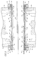
- a preferred embodiment of the press apparatus of the present invention is referenced generally as 10 and such is basically comprised of a press frame 12 and a pair of opposed platen assemblies 14 and 16 situated in the press throat area positioned between the press frame head portion 18 and press frame base portion 20 .
- upper platen assembly 14 may be moved vertically toward and from platen assembly 16 .
- Lower platen assembly 16 in the Figure 1 press configuration is fixedly mounted on the press frame base 20 .
- a work table element 22 is also provided adjacent platen assembly 16 and functions to support thermoplastic sheet material components inserted in apparatus 10 for thermal fusion.
- the platen assemblies 14 and 16 each have a diaphragm set 32 and 34 described in detail hereinbelow.
- Press apparatus 10 also includes two aluminum heater block assemblies 26 and 28 which each cooperate with, but are movable vertically with respect to, one of the platen assemblies 14 and 16. Heater block assembly 28 may be raised into engagement with the diaphragm set 34 of stationary platen assembly 16 or retracted out of engagement therewith by means of any conventional actuating means. Looking at Figures 2 through 5, it may be seen that the upper heater block assembly 26 carries platen assembly 14 and may be moved vertically by a press cylinder/piston combination (not shown). Platen assembly 14 includes a diaphragm set 32 which is mounted in a frame subassembly 36 having a plurality of vertical support members 38 .
- Support members 38 are connected to a pair of horizontal support members 37 which rest upon the top surface of heater block assembly 26 such that platen assembly 14 is loosely suspended from the heater block assembly 26 . Consequently, as heater block assembly 26 is lowered, diaphragm set 32 of platen assembly 14 also is lowered into contact with diaphragm set 34 of platen assembly 16 . Assembly 14 may be clamped into position against lower platen assembly 16 by a locking bar mechanism 41 . Subsequent to the engagement of upper platen assembly 14 with lower platen assembly 16 , heater block assembly 26 may be lowered further to contact diaphragm set 32 . From this it may be seen that heater block assembly 26 may be moved vertically a limited distance independently of platen assembly 14 . Of course, platen assembly 14 need not be suspended from heater block assembly 26 . Platen assembly 14 may be constructed to be raised and lowered vertically entirely independently of heater block assembly 26 .
- diaphragm sets 32 and 34 each are comprised of a pair of compliant membrane elements 40 and 42 .
- Each of the membrane elements 40 and 42 preferably is fabricated using a thin and commercially available fluid-impervious material such as a relatively thin, silicone and polytetrafluoroethylene film having embedded and cross-woven graphite fiber reinforcement strands. Glass fiber reinforcement strands also may be utilized.
- membrane elements 40 and 42 also preferably have the properties of being good conductors or transmitters of heat with excellent physical integrity at elevated operating temperatures in the range of 149°C (300°F) to 316°C (600°F).
- Platen assembly 14 includes a frame subassembly 36 comprised of an upper frame plate element 44 having an interior opening 46 , an upper frame plate element 48 having an interior opening 50 , a spacer frame gasket element 52 having an interior opening somewhat larger than either of interior openings 46 and 50 , and various fastener elements 54 and 56 for joining components 40 through 52 into a unitary subassembly 36 shown secured to support members 38 .
- the frame subassembly 36 included in lower platen assembly 16 is essentially comprised of the same elements 40 through 56 but secured to platen support elements 39 in a relatively inverted position.
- each platen assembly 14 and 16 includes a schematically illustrated fluid line 58 which functions to supply pressurized fluid to that assembly and which communicates with the interior of its respective diaphragm set 32 or 34 through an opening 60 in frame plate element 48 .
- Each of assemblies 14 and 16 also includes a schematically illustrated fluid line 62 which also communicates with the interior of its respective diaphragm set but through another opening 64 in frame plate element.
- Each of fluid lines 62 functions to flow pressurized fluid from within a diaphragm set interior.
- Valving and valve controls associated with fluid lines 58 and 62 are conventional and are not illustrated in the drawings.
- Figure 3 also illustrates two thermoplastic sheet workpieces 66 and 68 which are positioned intermediate platen assemblies 14 and 16 and that are to be subsequently joined into a unitary structure by the operation of apparatus 10 .
- workpieces 66 and 68 are shown suspended intermediate platen assemblies 14 and 16 ; in practice, however, those workpieces are supported on the lower platen frame assembly 36 and its surrounding work table 22 with the workpiece area at which the workpiece seam is to be formed being positioned in alignment with the diaphragm sets 32 and 34 of opposed platen assemblies 14 and 16 .
- FIGS. 4 and 5 are similar to Figure 3 but illustrate the positioning and operating condition of apparatus 10 at critical points in the method of apparatus operation.
- platen assembly 14 is advanced from its retracted position to a point where such workpieces become clamped in their proper position and between the opposed platen assembly plate elements 44 .
- Each of heater block elements 26 and 28 preferably in a preheated condition, is then advanced to a position whereby it contacts its respective cooperating diaphragm set 32 and 34 compliant membrane member 40 or 42 and also functions to additionally clamp workpieces 66 and 68 together, particularly in the seam area that is to be formed.
- a pressurized fluid frequently compressed air at an operating over pressure of approximately 69 kPa (10 psig) (pounds per square inch gauge) is introduced through fluid line 58 and retained in the interior of each diaphragm set 32 and 34 to further clamp the workpieces together.
- Fluid lines 62 previously are valved to a "closed” condition.
- heat is transferred from each heater block element 26 and 28 by conductance through membrane members 40 and 42 and into the workpieces. Heat transfer is continued for a sufficient time to cause the thermoplastic resin in the coextensive seam areas of workpieces 66 and 68 to fuse together.
- the time required for adequate seam area fusion may be to a little as 15 seconds.
- Figure 4 also illustrates the "inflated" condition of each of diaphragm sets 32 and 34 during workpiece seam area heating.
- each of heater block elements 26 and 28 is retracted (withdrawn).
- Pressurized fluid used in the processing is then caused to be flowed through each of diaphragm sets 32 and 34 to act as a coolant while the workpiece seam area remains fully restrained by the adjacent compliant membrane members 40 and 42 .
- the valving for fluid lines 62 is changed to an "open" condition and frequently the operating over pressure of the pressurized fluid is increased sufficiently (e.g., compressed air at 103.5 kPa (15 psig)) to give an adequate coolant flow rate.
- Adequate cooling often is accomplished in apparatus 10 in as little time as 30 to 60 seconds.
- locking bar mechanism 41 is unlocked to enable press platen assembly 14 and heater block assembly 26 to be returned to their initial, spaced-apart position relative to platen assembly 16 . Thereafter, the joined workpieces are then either removed from apparatus 10 or are moved to their next position on worktable 22 for continued seaming operations.
Landscapes
- Engineering & Computer Science (AREA)
- Mechanical Engineering (AREA)
- Physics & Mathematics (AREA)
- Thermal Sciences (AREA)
- Lining Or Joining Of Plastics Or The Like (AREA)
Claims (10)
- Gerät des Preßtyps zum thermischen Verbinden überlappter, thermoplastischer Folienwerkstücke, wobei das Gerät aufweist:ein plattenartiges Tischelement (22) mit einer Arbeitsfläche zum Tragen überlappter, thermoplastischer Folienwerkstücke (66, 68);eine Plattenbaugruppe (14) mit einem Rahmenelement (36), einer aufblasbaren Einrichtung, die von dem Rahmenelement (36) getragen ist und im wesentlichen die gleiche Ausdehnung wie das Rahmenelement aufweist, und Einrichtungen (58, 62) zum Leiten von Druckfluid zu der aufblasbaren Einrichtung und von derselben weg, und welche getragen ist zur Bewegung bis in Berührung und außer Berührung mit Werkstücken (66, 68), die auf dem plattenartigen Tischelement (22) liegen;eine Druckfluidquelle; undeine Steuereinrichtung zum Steuern der Bewegung der Plattenbaugruppe (14) und der Strömung des Druckfluids von der Druckfluidquelle zu der aufblasbaren Einrichtung und von derselben weg,
dadurch gekennzeichnet, daß die aufblasbare Einrichtung einen aufblasbaren Membransatz (32) aufweist mit zwei nachgiebigen Membranen (40, 42), und daß das Rahmenelement (36) eine Einsatzöffnung (46, 50) aufweist und ein plattenartiges Heizblockelement (26) die Einsatzöffnung (46, 50) des Rahmenelements überlagert und getragen ist zur Bewegung bis in Berührung und außer Berührung mit dem aufblasbaren Membransatz (32), und daß die Steuereinrichtung auch die Bewegung des Heizblockelementes (26) steuert, wobei die Steuereinrichtung die Bewegung des Heizelementes (26) unabhängig von der Bewegung der Plattenbaugruppe (14) steuert sowie die Strömung des Druckfluides steuert in und aus dem Raum zwischen den Membranen (40, 42) des Membransatzes (32) unabhängig von der Bewegung der Plattenbaugruppe (14) und unabhängig von der Bewegung des Heizblockelementes (26). - Gerät des Preßtyps zum thermischen Verbinden überlappter, thermoplastischer Folienwerkstücke (66, 68), wobei das Gerät aufweist: zwei gegenüberliegende Plattenbaugruppen (14, 16), wobei jede Plattenbaugruppe (14, 16) ein Rahmenelement (36) aufweist, eine aufblasbare Einrichtung, die von dem Rahmenelement (36) getragen ist, um im wesentlichen die gleiche Ausdehnung wie das Rahmenelement aufweist, und eine Einrichtung (58, 62) zum Leiten von Druckfluid zu der aufblasbaren Einrichtung und von derselben weg; Heizeinrichtungen; eine Druckfluidquelle; und eine Steuereinrichtung zum Steuern der Druckfluidströmung in die aufblasbare Einrichtung und von derselben weg,
dadurch gekennzeichnet, daß die aufblasbare Einrichtung einer jeden Plattenbaugruppe (14, 16) einen aufblasbaren Membransatz (32, 34) aufweist mit zwei nachgiebigen Membranen (40, 42), daß das Rahmenelement (36) einer jeden Plattenbaugruppe (14, 16) eine Einsatzöffnung (46, 50) aufweist, und die Heizeinrichtungen zwei plattenartige Heizblockelemente (26, 28) aufweisen, wobei jedes Heizblockelement (26, 28) eine zugehörige Einsatzöffnung (46, 50) der Rahmenelemente der zwei Plattenbaugruppen überlagert und getragen ist zur Bewegung bis in Berührung und außer Berührung mit einem zugehörigen Membransatz der zwei Membransätze (32, 34);und daß mindestens eine der Plattenbaugruppen (14, 16) getragen ist zur Bewegung bis in Berührung und außer Berührung mit den Werkstücken (66, 68), die auf der anderen der Plattenbaugruppen (14, 16) aufliegen,wobei die Steuereinrichtung auch die Bewegung der Platteneinrichtungen (14, 16) in bezug aufeinander und die Bewegung der Heizblockelemente (26, 28) in bezug auf die Membransätze (32, 34) steuert, und die Steuereinrichtung die Bewegung steuert der zwei Heizblockelemente (26, 28) unabhängig von der Bewegung der zwei Plattenbaugruppen (14, 16) und die Strömung des Druckfluides in und aus dem Raum zwischen den Membranen (40, 42) der Membransätze (32, 34) unabhängig von der Bewegung der Plattenbaugruppen (14, 16) in bezug aufeinander und unabhängig von der Bewegung der Heizblockelemente (26, 28). - Gerät nach Anspruch 1,dadurch gekennzeichnet, daß die nachgiebigen Membranen (40, 42) des Membransatzes (32) jeweils im wesentlichen fluidundurchlässig, nicht elastomerisch und thermisch leitend sind bei struktureller Unversehrtheit unter Gerätbetriebstemperaturen in dem Bereich von etwa 149°C (300 Grad F) bis zu 316° C (600 Grad F) sind.
- Gerät nach Anspruch 2, dadurch gekennzeichnet, daß die nachgiebigen Membranen (40, 42) der Membransätze (32, 34) jeweils im wesentlichen fluidundurchlässig, nicht elastomerisch und thermisch leitend sind bei struktureller Unversehrtheit unter Gerätbetriebstemperaturen in dem Bereich von etwa 149°C (300 Grad F) bis zu 316°C (600 Grad F).
- Verfahren zum Miteinanderverbinden von Werkstücken (66, 68) aus thermoplastischem Folienmaterial in einem Gerät des Preßtyps mit einer Platte (14), einem aufblasbaren Membransatz (32) mit zwei nachgiebigen Membranen (40, 42), welche in der Platte (14) vorgesehen sind, einer Wärmequelle (26), die beweglich ist bis in Berührung und außer Berührung mit dem aufblasbaren Membransatz (32), und einer Druckfluidquelle, wobei das Verfahren folgende Schritte aufweist:Einklemmen der Werkstücke (66, 68) in dem Preßtypgerät durch die Platte (14), wobei die Membranen (40, 42) des aufblasbaren Membransatzes (32) in einem nicht aufgeblasenen Zustand sind;Bewegen der Wärmequelle (26) bis in Berührung mit dem Membransatz (32), um somit das Erhitzen der eingeklemmten Werkstücke (66, 68) zu beginnen durch Wärmeleitung durch die Membranen (40, 42) des nicht aufgeblasenen Membransatzes (32);Aufblasen des Membransatzes (32) um ihren Umfang herum durch Druckfluidzuführung von der Druckfluidquelle in den Raum zwischen den Membranen (40, 42), um die eingeklemmten Werkstücke (66, 68) weiter zusammenzudrücken;Fortsetzen des Erhitzens der weiter zusammengedrückten Werkstücke (66, 68) durch Aufrechterhalten der Berührung der Wärmequelle mit dem aufgeblasenen Membransatz (32), bis die Werkstücke (66, 68) ausreichend erhitzt sind, zum Zwecke der thermischen Verbindung;Zurückziehen der Wärmequelle (26) außer Berührung mit dem aufgeblasenen Membransatz (32),Zuführen von Druckfluid von der Druckfluidquelle in den Raum zwischen den Membranen (40, 42) des Membransatzes (32) in einer ausreichenden Menge zum Kühlen der erhitzten und eingeklemmten Werkstücke (66, 68), um die Werkstücke (66, 68) während ihrer Einklemmung miteinander zu verbinden; undEntleeren des Membranpaares (40, 42) des aufgeblasenen Membransatzes (32) und Freigeben der verbundenen Werkstücke (66, 68) vor dem Entfernen der verbundenen Werkstücke (66, 68) aus dem Preßtypgerät.
- Verfahren nach Anspruch 5, wobei das Membranpaar (40, 42) des Membransatzes (32) um ihren Umfang herum aufgeblasen wird unter Benutzung eines Druckfluids unter einem Hochdruck in dem Bereich, welcher einen Druck von etwa 69 kPa (10 Pfund pro Quadratzoll) nicht übersteigt.
- Verfahren nach Anspruch 5, wobei die Wärmequelle (26) eine Temperatur aufweist in dem Bereich von etwa 149°C (300 Grad Fahrenheit) bis zum 316°C (600 Grad Fahrenheit).
- Verfahren zum Miteinanderverbinden von Werkstücken (66, 68) aus thermoplastischem Folienmaterial in einem Gerät des Preßtyps mit einem Paar von Plattenbaugruppen (14; 16), wobei jede Plattenbaugruppe (14, 16) einen aufblasbaren Membransatz (32, 34) aufweist, mit einem Paar von nachgiebigen Membranen (40, 42), einem Paar von Wärmequellen (26, 28), die jeweils beweglich sind bis in Berührung und außer Berührung mit einem Membransatz (32, 34), und einer Quelle von Druckfluid, wobei das Verfahren folgende Schritte aufweist:Einklemmen der Werkstücke (66, 68) in dem Preßtypgerät zwischen dem Paar von Plattenbaugruppen (14, 16), wobei die Membranpaare (40, 42) der aufblasbaren Membransätze (32, 34) in einem nicht aufgeblasenen Zustand sind;Bewegen der Wärmequellen (26, 28) bis in Berührung mit den Membransätzen (32, 34), um somit das Erhitzen der eingeklemmten Werkstücke (66, 68) zu beginnen durch Wärmeleitung durch die Membranen (40, 42) der nicht aufgeblasenen Membransätze (32, 34);Aufblasen der Membransätze (32, 34), um ihre Umfänge herum durch Druckfluidzuführung von der Druckfluidquelle zu den Membranpaaren (40, 42), um die eingeklemmten Werkstücke (66, 68) weiter zusammenzudrücken;Fortsetzen des Erhitzens der weiter zusammengedrückten Werkstücke (66, 68) durch Aufrechterhalten der Berührung der Wärmequellen (26, 28) mit den aufgeblasenen Membransätzen (32, 34) bis die Werkstücke (66, 68) ausreichend erhitzt sind zum Zwecke der thermischen Verbindung;Zurückziehen der Wärmequellen (26, 28) außer Berührung mit den aufgeblasenen Membransätzen (32, 34);Zuführen von Druckfluid von den Druckfluidquellen (26, 28) zwischen jedes Membranpaar (40, 42) des aufgeblasenen Membransatzes (32, 34) in einer ausreichenden Menge zum Kühlen der erhitzten und eingeklemmten Werkstücke (66, 68), um somit die Werkstücke (66, 68) während ihrer Einklemmung miteinander zu verbinden; undEntleeren jedes Membranpaares (40, 42) des aufgeblasenen Membransatzes (32, 34) und vollständiges Freigeben der verbundenen Werkstücke (66, 68) durch Öffnen der Plattenbaugruppen (14, 16) in bezug aufeinander vor dem Entfernen der verbundenen Werkstücke (66, 68) aus dem Preßtypgerät.
- Verfahren nach Anspruch 8, wobei die Membranpaare (40, 42) des Membransatzes (32, 34) aufgeblasen werden, um ihre Umfänge herum unter Benutzung eines Fluides unter einem Überdruck der etwa 69 kPa (10 Pfund pro Quadratzoll) nicht übersteigt.
- Verfahren nach Anspruch 8, wobei die Wärmequellen (26, 28) eine Temperatur aufweisen, die in dem Bereich von etwa 149°C (300 Grad F) bis zu 316°C (600 Grad F) liegt.
Applications Claiming Priority (2)
| Application Number | Priority Date | Filing Date | Title |
|---|---|---|---|
| US492214 | 1995-06-19 | ||
| US08/492,214 US5635014A (en) | 1995-06-19 | 1995-06-19 | Press apparatus and methods for fusing overlapped thermoplastic sheet materials |
Publications (3)
| Publication Number | Publication Date |
|---|---|
| EP0749824A2 EP0749824A2 (de) | 1996-12-27 |
| EP0749824A3 EP0749824A3 (de) | 1997-07-30 |
| EP0749824B1 true EP0749824B1 (de) | 1999-09-22 |
Family
ID=23955405
Family Applications (1)
| Application Number | Title | Priority Date | Filing Date |
|---|---|---|---|
| EP96630035A Expired - Lifetime EP0749824B1 (de) | 1995-06-19 | 1996-06-06 | Pressvorrichtung und Verfahren zur Überlappungsschweissen von thermoplastischen Folien |
Country Status (5)
| Country | Link |
|---|---|
| US (2) | US5635014A (de) |
| EP (1) | EP0749824B1 (de) |
| JP (1) | JPH091664A (de) |
| CA (1) | CA2176689C (de) |
| DE (1) | DE69604339T2 (de) |
Families Citing this family (49)
| Publication number | Priority date | Publication date | Assignee | Title |
|---|---|---|---|---|
| AUPO531397A0 (en) * | 1997-02-25 | 1997-03-20 | Kory Dubay Manufacturing Pty Ltd | Improvements to diaphragm press |
| GB9719782D0 (en) * | 1997-09-17 | 1997-11-19 | Mirical Emblems Ltd | Method and apparatus for controlling heat bonding |
| US6009925A (en) * | 1998-02-05 | 2000-01-04 | Hall Dielectric Machinery, Inc. | Apparatus for welding thermoplastic materials |
| US6793479B1 (en) * | 1998-04-17 | 2004-09-21 | Alliant Techsystems Inc. | Remotely actuated localized pressure and heat apparatus and method of use |
| US5972149A (en) * | 1998-04-20 | 1999-10-26 | Milsco Manufacturing Company | Method for making a seat using a pressured bladder |
| US6228200B1 (en) * | 1999-09-09 | 2001-05-08 | Belt Equipment, Inc. | Belt press using differential thermal expansion |
| DE19962081A1 (de) * | 1999-12-21 | 2001-06-28 | Buerkle Gmbh Robert | Verfahren und Vorrichtung zur Herstellung laminierter Plastikkarten |
| TW475227B (en) * | 1999-12-28 | 2002-02-01 | Nissei Plastics Ind Co | IC-card manufacturing apparatus |
| US7831151B2 (en) | 2001-06-29 | 2010-11-09 | John Trezza | Redundant optical device array |
| ITMI20020153A1 (it) * | 2002-01-29 | 2003-07-29 | Thermo Engineering Srl | Impianto continuo per laminati plastici compresi i multistrato in pressa fredda |
| EP1334820A3 (de) * | 2002-02-07 | 2005-04-13 | W.C. Heraeus GmbH | Pressestempel für eine Laminierpresse und Verwendung |
| US6752901B2 (en) * | 2002-04-05 | 2004-06-22 | Heinrich Wemhoener Gmbh & Co. Kg | Coating press for sheet-like work-pieces |
| US20040028365A1 (en) * | 2002-08-09 | 2004-02-12 | Abds-Sami Malik | Metal oxide coated fiber and methods for coating an optical fiber with a metal oxide coating |
| US7112054B2 (en) * | 2002-08-09 | 2006-09-26 | The Boeing Company | Consolidation joining of thermoplastic laminate ducts |
| US7097804B2 (en) | 2002-08-09 | 2006-08-29 | The Boeing Company | Thermoplastic laminate duct |
| US7153124B2 (en) * | 2002-08-09 | 2006-12-26 | The Boeing Company | Preforming thermoplastic ducts |
| US7128558B2 (en) * | 2002-08-09 | 2006-10-31 | The Boeing Company | Post-forming of thermoplastic ducts |
| US7521806B2 (en) * | 2005-06-14 | 2009-04-21 | John Trezza | Chip spanning connection |
| US7687400B2 (en) | 2005-06-14 | 2010-03-30 | John Trezza | Side stacking apparatus and method |
| US7560813B2 (en) | 2005-06-14 | 2009-07-14 | John Trezza | Chip-based thermo-stack |
| US20060278996A1 (en) * | 2005-06-14 | 2006-12-14 | John Trezza | Active packaging |
| US7838997B2 (en) | 2005-06-14 | 2010-11-23 | John Trezza | Remote chip attachment |
| US7786592B2 (en) | 2005-06-14 | 2010-08-31 | John Trezza | Chip capacitive coupling |
| US7767493B2 (en) | 2005-06-14 | 2010-08-03 | John Trezza | Post & penetration interconnection |
| US8456015B2 (en) | 2005-06-14 | 2013-06-04 | Cufer Asset Ltd. L.L.C. | Triaxial through-chip connection |
| US7946331B2 (en) * | 2005-06-14 | 2011-05-24 | Cufer Asset Ltd. L.L.C. | Pin-type chip tooling |
| US7534722B2 (en) * | 2005-06-14 | 2009-05-19 | John Trezza | Back-to-front via process |
| US7781886B2 (en) * | 2005-06-14 | 2010-08-24 | John Trezza | Electronic chip contact structure |
| US7851348B2 (en) | 2005-06-14 | 2010-12-14 | Abhay Misra | Routingless chip architecture |
| US7687397B2 (en) * | 2006-06-06 | 2010-03-30 | John Trezza | Front-end processed wafer having through-chip connections |
| US7670874B2 (en) | 2007-02-16 | 2010-03-02 | John Trezza | Plated pillar package formation |
| JP2008307724A (ja) * | 2007-06-13 | 2008-12-25 | Nisshinbo Ind Inc | ラミネート装置 |
| US8092631B2 (en) | 2008-02-28 | 2012-01-10 | Solmax International Inc. | Apparatus and die for welding plastic and a method of use thereof |
| WO2010011764A1 (en) * | 2008-07-22 | 2010-01-28 | Hunter Douglas Industries B.V. | Efficient lamination press with flexible platens |
| US9199439B2 (en) | 2008-07-22 | 2015-12-01 | 3Form, Llc | Efficient lamination press with thin flexible platens |
| DE102009014249B4 (de) * | 2009-03-20 | 2012-12-27 | Smartrac Ip B.V. | Mehrschichtige thermoplastische laminierte Folienanordnung sowie Vorrichtung und Verfahren zum Laminieren |
| US8627867B2 (en) * | 2009-04-21 | 2014-01-14 | Bae Systems Information And Electronic Systems Integration Inc. | System and method for microelectronics lamination press |
| US8329262B2 (en) * | 2010-01-05 | 2012-12-11 | Applied Materials, Inc. | Dielectric film formation using inert gas excitation |
| US10000922B1 (en) | 2011-03-24 | 2018-06-19 | Firestone Building Products Co., LLC | Construction boards with coated inorganic facer |
| US10569530B2 (en) | 2012-03-06 | 2020-02-25 | Stahls' Inc. | Threadable heat transfer press with heated lower platen |
| DE102013208127A1 (de) * | 2013-05-03 | 2014-11-06 | Homag Holzbearbeitungssysteme Gmbh | Heißgaserzeugungseinrichtung |
| EP3455426A1 (de) | 2016-05-14 | 2019-03-20 | Firestone Building Products Co., LLC | Verbunddämmplatten mit klebender rückseite mit vakuumisolierten kapseln |
| WO2018035526A1 (en) | 2016-08-19 | 2018-02-22 | Firestone Building Products Co., LLC | Process for producing isocyanate-based foam construction boards |
| WO2018175316A1 (en) | 2017-03-20 | 2018-09-27 | Firestone Building Products Company, Llc | Process for producing isocyanate-based foam construction boards |
| US20200055275A1 (en) | 2017-05-05 | 2020-02-20 | Firestone Building Products Company, Llc | Foam construction boards with enhanced fire performance |
| US20250137256A1 (en) | 2022-02-04 | 2025-05-01 | Holcim Technology Ltd | Method for constructing a roof system using adhesive transfer films adhering construction components |
| CA3253407A1 (en) | 2022-03-15 | 2023-09-21 | Amrize Technology Switzerland Llc | PRECURSOR COMPOSITE FOR SEALING TAPE AND ITS METHODS OF USE |
| EP4688424A1 (de) | 2023-03-31 | 2026-02-11 | Holcim Technology Ltd. | Dachsystem mit aufgeklebten bauplatten |
| WO2026074032A1 (en) | 2024-10-02 | 2026-04-09 | Holcim Technology Ltd | Roof system and composite boards with encapsulated fragile insulation materials |
Family Cites Families (16)
| Publication number | Priority date | Publication date | Assignee | Title |
|---|---|---|---|---|
| US3580795A (en) * | 1966-10-05 | 1971-05-25 | John E Eichenlaub | Apparatus for welding heat sealable sheet material |
| US4421589A (en) * | 1982-07-13 | 1983-12-20 | Spire Corporation | Laminator for encapsulating multilayer laminate assembly |
| JPS5979730A (ja) * | 1982-10-30 | 1984-05-09 | Toyota Motor Corp | 接着方法 |
| US4529472A (en) * | 1982-11-10 | 1985-07-16 | Wei K. Hsu | Impulse sealing apparatus |
| JPS6198529A (ja) * | 1984-10-19 | 1986-05-16 | Bridgestone Corp | 加硫加圧装置 |
| WO1987004973A1 (en) * | 1986-02-20 | 1987-08-27 | Libbey-Owens-Ford Co. | Seal construction for a mold structure for encapsulating glass with a gasket |
| US4744845A (en) * | 1986-09-12 | 1988-05-17 | Baxter Travenol Laboratories, Inc. | Apparatus for splicing film together |
| US4732553A (en) * | 1987-07-06 | 1988-03-22 | Libbey-Owens-Ford Co. | Seal construction for a mold structure for encapsulating glass with a gasket |
| DE3869338D1 (en) * | 1987-09-28 | 1992-04-23 | Windmoeller & Hoelscher | Welding together thermoplastic sheets |
| JPH02113923A (ja) * | 1988-10-25 | 1990-04-26 | Kureha Rubber Kogyo Kk | マットの製造法 |
| DE3902522A1 (de) * | 1989-01-28 | 1990-08-16 | Niederberg Chemie | Schweissen von kunststoffabdichtungsbahnen in erdschlitzen |
| JPH0383630A (ja) * | 1989-08-29 | 1991-04-09 | Bridgestone Corp | タイヤ構成部材の圧着装置 |
| DE4108936A1 (de) * | 1991-03-19 | 1992-09-24 | Kannegiesser H Gmbh Co | Vorrichtung zum verkleben textiler flaechengebilde |
| US5366580A (en) * | 1992-01-08 | 1994-11-22 | Cosmos Electronic Machine Corp. | High frequency welding machine |
| FR2691099B1 (fr) * | 1992-05-13 | 1997-07-04 | Dassault Aviat | Dispositif pour solidariser entre eux des objets en materiaux composites par application simultanee de chaleur et de pression. |
| US5472549A (en) * | 1994-07-08 | 1995-12-05 | Enclosure Technologies, Inc. | Apparatus for electronically seam fusing dissimilar polymeric materials |
-
1995
- 1995-06-19 US US08/492,214 patent/US5635014A/en not_active Expired - Fee Related
-
1996
- 1996-05-15 CA CA002176689A patent/CA2176689C/en not_active Expired - Fee Related
- 1996-06-06 DE DE69604339T patent/DE69604339T2/de not_active Expired - Fee Related
- 1996-06-06 EP EP96630035A patent/EP0749824B1/de not_active Expired - Lifetime
- 1996-06-18 JP JP8177526A patent/JPH091664A/ja active Pending
- 1996-12-23 US US08/771,508 patent/US5725711A/en not_active Expired - Fee Related
Also Published As
| Publication number | Publication date |
|---|---|
| DE69604339T2 (de) | 2000-05-18 |
| EP0749824A3 (de) | 1997-07-30 |
| CA2176689A1 (en) | 1996-12-20 |
| JPH091664A (ja) | 1997-01-07 |
| CA2176689C (en) | 2000-03-28 |
| DE69604339D1 (de) | 1999-10-28 |
| US5725711A (en) | 1998-03-10 |
| EP0749824A2 (de) | 1996-12-27 |
| US5635014A (en) | 1997-06-03 |
Similar Documents
| Publication | Publication Date | Title |
|---|---|---|
| EP0749824B1 (de) | Pressvorrichtung und Verfahren zur Überlappungsschweissen von thermoplastischen Folien | |
| US20030146543A1 (en) | Molding method and support system for thermoformable sheet material | |
| US2702411A (en) | Method for forming and embossing thermoplastic materials | |
| JP2695348B2 (ja) | 射出成形同時絵付装置 | |
| US4062718A (en) | Heat sealing means | |
| US4960478A (en) | Apparatus and process for the fusion bonding of thermoplastic articles | |
| US5820813A (en) | Method for producing multilayer molded article | |
| US5865924A (en) | Heat sealing of thread to a web | |
| WO1990011185A1 (en) | Roll-consolidation of thermoplastic composite laminates | |
| EP1024941B1 (de) | Vorrichtung und verfahren zum blasformen von zwei thermoplastischen folien unter verwendung von pneumatischen verschiebbaren membranen zum schliessen der formhälften | |
| JPH03262607A (ja) | 複合材部品成形型 | |
| US2859796A (en) | Means for sealing materials by heat | |
| TWI763167B (zh) | 熱成形裝置 | |
| JPH06315950A (ja) | 射出成形同時絵付方法および装置 | |
| US2705523A (en) | Heat-seaming apparatus for thermoplastic sheet materials | |
| CN113001946A (zh) | 一种真空热成型系统及其成型方法 | |
| US2997098A (en) | Sealing apparatus | |
| GB2056907A (en) | Apparatus for welding thermoplastic layers | |
| US3600248A (en) | Method for heat sealing thermoplastic bodies | |
| KR960013173B1 (ko) | 열교환기용 박막 전열 열교환판의 제조방법 | |
| GB2101927A (en) | Moulding apparatus | |
| US20240300195A1 (en) | Method of forming composites by joule heating of enveloping metallic sheets | |
| US3810806A (en) | Thermoplastic heat sealing apparatus | |
| JPH06297878A (ja) | ファイルの製造方法 | |
| US5445310A (en) | Method for sheet metal and thermoplastic adhesive bonded assemblies and brazed bonded assemblies in 360° shapes |
Legal Events
| Date | Code | Title | Description |
|---|---|---|---|
| PUAI | Public reference made under article 153(3) epc to a published international application that has entered the european phase |
Free format text: ORIGINAL CODE: 0009012 |
|
| AK | Designated contracting states |
Kind code of ref document: A2 Designated state(s): CH DE FR GB IT LI SE |
|
| PUAL | Search report despatched |
Free format text: ORIGINAL CODE: 0009013 |
|
| AK | Designated contracting states |
Kind code of ref document: A3 Designated state(s): CH DE FR GB IT LI SE |
|
| 17P | Request for examination filed |
Effective date: 19971208 |
|
| 17Q | First examination report despatched |
Effective date: 19980415 |
|
| GRAG | Despatch of communication of intention to grant |
Free format text: ORIGINAL CODE: EPIDOS AGRA |
|
| GRAG | Despatch of communication of intention to grant |
Free format text: ORIGINAL CODE: EPIDOS AGRA |
|
| GRAH | Despatch of communication of intention to grant a patent |
Free format text: ORIGINAL CODE: EPIDOS IGRA |
|
| GRAH | Despatch of communication of intention to grant a patent |
Free format text: ORIGINAL CODE: EPIDOS IGRA |
|
| GRAA | (expected) grant |
Free format text: ORIGINAL CODE: 0009210 |
|
| AK | Designated contracting states |
Kind code of ref document: B1 Designated state(s): CH DE FR GB IT LI SE |
|
| PG25 | Lapsed in a contracting state [announced via postgrant information from national office to epo] |
Ref country code: SE Free format text: THE PATENT HAS BEEN ANNULLED BY A DECISION OF A NATIONAL AUTHORITY Effective date: 19990922 Ref country code: IT Free format text: LAPSE BECAUSE OF FAILURE TO SUBMIT A TRANSLATION OF THE DESCRIPTION OR TO PAY THE FEE WITHIN THE PRESCRIBED TIME-LIMIT;WARNING: LAPSES OF ITALIAN PATENTS WITH EFFECTIVE DATE BEFORE 2007 MAY HAVE OCCURRED AT ANY TIME BEFORE 2007. THE CORRECT EFFECTIVE DATE MAY BE DIFFERENT FROM THE ONE RECORDED. Effective date: 19990922 |
|
| REG | Reference to a national code |
Ref country code: CH Ref legal event code: EP |
|
| REF | Corresponds to: |
Ref document number: 69604339 Country of ref document: DE Date of ref document: 19991028 |
|
| ET | Fr: translation filed | ||
| PGFP | Annual fee paid to national office [announced via postgrant information from national office to epo] |
Ref country code: FR Payment date: 20000518 Year of fee payment: 5 |
|
| PGFP | Annual fee paid to national office [announced via postgrant information from national office to epo] |
Ref country code: CH Payment date: 20000522 Year of fee payment: 5 |
|
| PGFP | Annual fee paid to national office [announced via postgrant information from national office to epo] |
Ref country code: GB Payment date: 20000523 Year of fee payment: 5 |
|
| PGFP | Annual fee paid to national office [announced via postgrant information from national office to epo] |
Ref country code: DE Payment date: 20000524 Year of fee payment: 5 |
|
| PLBE | No opposition filed within time limit |
Free format text: ORIGINAL CODE: 0009261 |
|
| STAA | Information on the status of an ep patent application or granted ep patent |
Free format text: STATUS: NO OPPOSITION FILED WITHIN TIME LIMIT |
|
| 26N | No opposition filed | ||
| PG25 | Lapsed in a contracting state [announced via postgrant information from national office to epo] |
Ref country code: GB Free format text: LAPSE BECAUSE OF NON-PAYMENT OF DUE FEES Effective date: 20010606 |
|
| PG25 | Lapsed in a contracting state [announced via postgrant information from national office to epo] |
Ref country code: LI Free format text: LAPSE BECAUSE OF NON-PAYMENT OF DUE FEES Effective date: 20010630 Ref country code: CH Free format text: LAPSE BECAUSE OF NON-PAYMENT OF DUE FEES Effective date: 20010630 |
|
| GBPC | Gb: european patent ceased through non-payment of renewal fee |
Effective date: 20010606 |
|
| REG | Reference to a national code |
Ref country code: CH Ref legal event code: PL |
|
| PG25 | Lapsed in a contracting state [announced via postgrant information from national office to epo] |
Ref country code: FR Free format text: LAPSE BECAUSE OF NON-PAYMENT OF DUE FEES Effective date: 20020228 |
|
| PG25 | Lapsed in a contracting state [announced via postgrant information from national office to epo] |
Ref country code: DE Free format text: LAPSE BECAUSE OF NON-PAYMENT OF DUE FEES Effective date: 20020403 |