EP0749849A2 - Ein Band für Bücher mit biegsamen Deckeln - Google Patents
Ein Band für Bücher mit biegsamen Deckeln Download PDFInfo
- Publication number
- EP0749849A2 EP0749849A2 EP96202758A EP96202758A EP0749849A2 EP 0749849 A2 EP0749849 A2 EP 0749849A2 EP 96202758 A EP96202758 A EP 96202758A EP 96202758 A EP96202758 A EP 96202758A EP 0749849 A2 EP0749849 A2 EP 0749849A2
- Authority
- EP
- European Patent Office
- Prior art keywords
- roller
- adhesive
- book block
- speed
- book
- Prior art date
- Legal status (The legal status is an assumption and is not a legal conclusion. Google has not performed a legal analysis and makes no representation as to the accuracy of the status listed.)
- Withdrawn
Links
Images




Classifications
-
- B—PERFORMING OPERATIONS; TRANSPORTING
- B42—BOOKBINDING; ALBUMS; FILES; SPECIAL PRINTED MATTER
- B42C—BOOKBINDING
- B42C9/00—Applying glue or adhesive peculiar to bookbinding
- B42C9/0006—Applying glue or adhesive peculiar to bookbinding by applying adhesive to a stack of sheets
-
- B—PERFORMING OPERATIONS; TRANSPORTING
- B42—BOOKBINDING; ALBUMS; FILES; SPECIAL PRINTED MATTER
- B42C—BOOKBINDING
- B42C9/00—Applying glue or adhesive peculiar to bookbinding
- B42C9/0006—Applying glue or adhesive peculiar to bookbinding by applying adhesive to a stack of sheets
- B42C9/0012—Applying glue or adhesive peculiar to bookbinding by applying adhesive to a stack of sheets with a roller
-
- B—PERFORMING OPERATIONS; TRANSPORTING
- B42—BOOKBINDING; ALBUMS; FILES; SPECIAL PRINTED MATTER
- B42D—BOOKS; BOOK COVERS; LOOSE LEAVES; PRINTED MATTER CHARACTERISED BY IDENTIFICATION OR SECURITY FEATURES; PRINTED MATTER OF SPECIAL FORMAT OR STYLE NOT OTHERWISE PROVIDED FOR; DEVICES FOR USE THEREWITH AND NOT OTHERWISE PROVIDED FOR; MOVABLE-STRIP WRITING OR READING APPARATUS
- B42D1/00—Books or other bound products
- B42D1/02—Books or other bound products in which the fillings and covers are connected by end papers
-
- B—PERFORMING OPERATIONS; TRANSPORTING
- B42—BOOKBINDING; ALBUMS; FILES; SPECIAL PRINTED MATTER
- B42D—BOOKS; BOOK COVERS; LOOSE LEAVES; PRINTED MATTER CHARACTERISED BY IDENTIFICATION OR SECURITY FEATURES; PRINTED MATTER OF SPECIAL FORMAT OR STYLE NOT OTHERWISE PROVIDED FOR; DEVICES FOR USE THEREWITH AND NOT OTHERWISE PROVIDED FOR; MOVABLE-STRIP WRITING OR READING APPARATUS
- B42D1/00—Books or other bound products
- B42D1/06—Books or other bound products in which the fillings and covers are united by other means
Definitions
- This invention relates to a book structure and to a method of binding a book block, using polyurethane adhesive (PUR) as a binding adhesive.
- PUR polyurethane adhesive
- Polyurethane adhesive is desirable as an adhesive for book binding.
- the polyurethane adhesive cures to form a film that strongly adheres to the page edges exposed at the book block spine, but is pliable and permits easy opening of the book.
- adhesives are applied to a book block spine using a roller.
- the roller is immersed within a pan containing a quantity of liquid adhesive.
- the adhesive clings to the roller surface for transfer to book blocks passing over the top of the roller.
- the book block spines receive the adhesive from the roller surface.
- the use of PUR adhesive in book binding is enhanced by use of a hot melt gap glue occupying an interface between the book block and a binding crepe.
- a teflon (TM) coated roller is used, but without the pan of the prior system. Instead an inclined trough having a lower edge located adjacent the roller meters PUR onto the roller.
- the trough defines a metering slit at its leading edge and the roller surface.
- the liquid PUR is deposited (e.g. from a transfer tube) onto thee trough and flows down the trough, through the metering slit and onto the roller.
- the PUR clings to the roller surface as the roller rotates under and back up the opposite side to be transferred onto the book block spine.
- the trough may be pivoted to drive the leading edge onto the roller and cease metering.
- the trough need only contain enough PUR to coat a small number of book blocks, e.g., 6-10 book blocks.
- the process may run through the extra limited number of book blocks to exhaust the PUR supply, or the excess PUR is simply captured in a separate container.
- the problem of clean up is not entirely eliminated, but is significantly reduced at a substantial savings in time and material.
- FIG. 1 shows the polyurethane adhesive (PUR) delivery portions of a book binding machine in accordance with the present invention.
- the preferred embodiment of the present invention has been implemented in a Muller Martini 30 Clamp Star Perfect Binder.
- the PUR delivery system shown in FIGS. 1-4 can be integrated into the Muller binding machine in place of its book spine hot melt adhesive applying station.
- the Muller machine comprises many components independently mounted and modularly interchangeable. It will be further understood, therefore, that integration of such PUR delivery system into the Muller Martini Perfect Binders or any other binding machinery, given the disclosure of the PUR delivery system herein, is within the capability of one of ordinary skill in the book binding art.
- a book block 10 travels from left to right as shown across a teflon coated PUR roller 12.
- Roller 12 carries PUR for delivery upon the spine 14 of the book block 10 as the block passes over the roller.
- a PUR source 16 includes an outlet nozzle 18 for depositing PUR 20 onto an inclined trough 22 having a leading edge 22a positioned adjacent roller 12.
- Leading edge 22a is defined by a replaceable teflon wear plate 25 mounted by screws 27 upon the body of trough 22.
- a spine plate 22b of trough 22 rests substantially vertically in the machine and is attached to the rear of the trough by screws 23.
- Spine plate 22b includes an oversized notch formation 22c for receiving the nozzle 18 of PUR 20 over the top edge 22d of trough 22.
- the PUR 20 then flows by gravity on the trough 22 from the nozzle 18 down to the leading edge 22a and contacts the roller 12.
- PUR 20 is metered onto roller 12 as a function of the separation between the leading edge 22a and the roller 12.
- the trough 22 is attached by screws 26 to a support rod 28 rotatably mounted by bearing arrangement 96 (FIG.3) for pivoting of the trough, as indicated by arrows 30, about the axis of the rod.
- a double ended pneumatic cylinder 24 controls the spacing between the leading edge 22a of the trough 22 and the roller 12 by pivoting the trough 22 so that the leading edge moves away from and toward the roller.
- Pneumatic cylinder 24 is coupled pivotally at its upper piston end 24a to a pin 32 pivotally mounted within blocks 22e (one of which is visible in FIG. 1) on the underside of the trough 22.
- the body of cylinder 24 is pivotally mounted on a frame portion (not shown in FIG. 1) of the machine.
- a distal lower piston end 24b of cylinder 24 extends downward and toward an inclined surface 37 of a block 38.
- a clevis 34 is threadably mounted on piston end 24b and carries a bearing assembly 35 thereon.
- the outer race 35a of the bearing assembly 35 engages the inclined surface 37 of the block 38 upon actuation of cylinder 24 toward the block which is mounted upon a carriage plate 39 which also carries rack gears 40.
- the carriage plate 39, and therefore the block 38 and the rack gears 40, are slidably mounted upon the book binding machine.
- a gear assembly 41 slides the carriage plate 39 by way of rack gears 40 and 40' for precise positioning of block 38 relative to pneumatic cylinder 24.
- An input shaft 43 (FIG. 2) couples to a first gear 42 which engages a larger second gear 44 carrying, by way of shaft 47, an inner gear 46 which engages a rack engaging gear 48.
- Coupling shaft 47 rotatably mounts upon side frame walls 49 and connects the first mentioned gear 46 to a similar gear 46' of gear assembly 41b.
- the gear 46' of assembly 41b then couples to a second rack engaging gear 48'.
- a second rack gear 40' also mounts upon the slidable carriage plate 39 for engagement by the gear 48'.
- the carriage plate 39 thereby moves uniformly between side frame walls 49 under the influence of gear assembly 41.
- the gear train 44, 46 and 48 of assembly 41a and the gear train 46', 48' of assembly 41b provides left and right movement of rack gears 40 and 40', in the view of FIGS. 1 and 2, as indicated at reference numeral 50.
- the input gear 42 carries 32 teeth
- the larger gear 44 carries 144 teeth
- the gears 46 and 46' each carry 36 teeth
- the rack engaging gears 48 and 48' each carry 90 teeth.
- input gear 42 is manually adjusted through 270 degrees of rotation for selected positioning of block 38 relative to pneumatic cylinder 24 to accomplish selected metering of PUR 20 upon roller 12. More particularly, moving block 38 toward cylinder 24 limits the throw of piston end 24b. As a result, edge 22a moves a lesser distance from roller 12 relative to that possible when block 38 is moved away from cylinder 24.
- the overall range of pivoting movement of leading edge 22a relative to roller 12 is on the order of 0.32 cm (one-eighth inch) as input shaft 43 moves through 270 degrees. Within that range, however, gear assembly 41 provides a high degree of metering precision for application of PUR 20 to roller 12.
- the cylinder 24 is actuated to draw leading edge 22a away from roller 12 to its greatest extent possible as defined by the position of block 38. This adjustment determines the spacing between edge 22a and roller 12 and, therefore, the amount of PUR 20 deposited on roller 12 upon actuation of cylinder 24.
- Leading edge 22a could be left in a retracted position during operation to constantly meter PUR 20 onto roller 12.
- Cylinder 24 is, however, actuated intermittently to push leading edge 22a against roller 12 to controllably cease metering of PUR 20 onto roller 12.
- actuation of pneumatic cylinder 24 may be timed to dispense a given amount of PUR 20 upon roller 12 to coincide with passage of book block 10 over roller 10.
- the top and bottom 0.16 cm (one-sixteenth inch) of the book block 10 not be coated with PUR 20. Accordingly, the circumferential distance through which roller 12 rotates while trough 22 is disengaged from roller 12 by pneumatic cylinder 24 corresponds to the length of book block 12, preferably minus 0.32 cm (one-eighth inch), and positioned for suitable delivery upon the book spine 14 as block 10 passes.
- a teflon (TM) coated back spinner roller 60 positioned down stream from roller 12, and moving in the opposite rotational direction of roller 12, removes excess PUR 20a from book spine 14 and performs a final metering step.
- An inclined scraper blade 62 (intermediate of rollers 12 and 60) engages roller 60 to remove from roller 60 the PUR 20a taken from book spine 14. Scraper blade 20 rests above trough 22 to return PUR 20a to the body of PUR 20 on trough 22.
- Back spinner roller 60 is vertically positionable relative to the path of book block 10 as indicated at reference numeral 61 to achieve precise final metering of PUR 20b on book spine 14.
- the back spinner roller 60 is typically positioned between 0.02 cm and 038 cm (0.008 and 0.015 inches) from book spine 14 whereby a thin film of PUR 20b remains upon spine 14 of book block 10 as it exits the PUR delivery operation.
- the temperature of PUR 20 should be maintained at sufficient level to prevent premature cross linking and also to prevent the introduction of hazardous by-products into the work environment.
- the trough 22 includes apertures 70 for receiving heater units 71 whereby the PUR 20 resting upon trough 22 is maintained at the desired temperature.
- the rollers 12 and 60 are heated rollers also maintained at the desired temperature.
- the PUR source 16 delivers PUR 20 to the trough 22 at the desired temperature.
- PUR 20 should be maintained at a constant temperature in a range of 110 to 121 degrees centigrade (230 to 250 degrees Fahrenheit). If the temperature rises above 121 degrees centigrade (250 degrees Fahrenheit), hazardous gas emissions result.
- a desiccated air or nitrogen source 72 may be provided for introducing desiccated air or nitrogen onto the body of PUR 20 resting on trough 22 to further isolate PUR 20 from ambient moisture.
- a second consideration in working with PUR 20 as an adhesive for book binding is the frequent shut down of the book binding machinery. This can represent a significant problem when working with PUR 20 because it is difficult to clean PUR 20 from the machine once cross linking begins.
- Use of trough 22 in the PUR delivery system requires only a small quantity of PUR 20 at any given time. More particularly, trough 22 need only contain sufficient PUR 20 to apply to a limited number of book blocks 10, e.g., to only 6-10 book blocks 10.
- the prior methods of PUR delivery included a substantially larger volume of PUR needed to immerse the dispensing roller. Thus, clean up is minimized under the present invention especially when PUR source 16 can be first shut down and several additional book blocks 10 processed to exhaust the supply of PUR 20 resting on trough 22.
- a differential temperature sensing method is employed.
- a low sensor 80 is positioned close to trough 22 while an upper temperature 82 sensor rests further above trough 22.
- the control system monitors the output from sensors 80 and 82 and determines when the volume of PUR 20 in trough 22 is low enough to require activation of PUR source 16, i.e., when to deliver additional PUR 20.
- the control system concludes that the temperature sensor 80 is immersed in the PUR 20 and that the temperature sensor 82 is not. Additional PUR 20 is then dispensed onto trough 22 until temperature sensors 80 and 82 provide substantially equal output, i.e., until both temperature sensors 80 and 82 are immersed in the body of PUR 20.
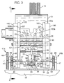
- FIG. 3 is an end view of the binding machinery shown in FIG. 1 taken along lines 3-3 of FIG. 1, but omitting the PUR source 16 and the back spinner roller 60.
- FIG. 3 the left gear assembly 41a and right gear assembly 41b are shown with the coupling shaft 47 (broken away) therebetween for movement of carriage plate 39. It is suggested that the under surface 94 of carriage plate 39 include a low friction interface with the frame 96 of the book binding machine for suitable movement of carriage plate 39.
- FIG. 3 also shows the central positioning of cylinder 24 and block 38 and both the blocks 22e for supporting the pin 32 at the under surface of trough 22.
- FIG. 3 further illustrates bearing mounts 96 in side walls 100 for rotationally supporting the shaft 28 and allowing pivotal support of trough 22.
- the body of pneumatic cylinder 24 is attached to a support shaft 99 at the screws 98.
- Support shaft 99 is rotationally supported by the side walls 100 by way of bearing mounts 97 in walls 100.
- Support shaft 99 (broken away in FIG. 3) includes an aperture 95 allowing passage therethrough of the clevis 34 and bearing assembly 35 for engagement with the block 38.
- bracing shaft 101 Relative spacing of side walls 100 is maintained by bracing shaft 101, of which only one is shown in FIG. 3. It will be understood, however, that several such bracing shafts 101 may be necessary to suitably maintain a spaced and face-to-face relation between side walls 100.
- the inner or opposing surfaces 100a of side walls 100 carry teflon (TM) containment walls 102.
- Containment walls 102 abut the outer edges 22f of trough 22 for containment of the body of PUR 20 resting on the inclined surface of trough 22.
- the opposing faces 102a of containment walls 102 thereby slidably engage the edges 22f of trough 22 as trough 22 pivots during operation.
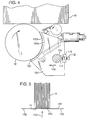
- FIG. 4 shows a side view taken along lines 4-4 of FIG. 3 showing the interface between the side walls 100, containment walls 102, and the PUR roller 12. More particularly, the leading edges 100b and 102b of side walls 100 and containment walls 102, respectively, have a radius of curvature matching that of PUR roller 12. The leading edges 102b engage roller 12 for sealing the interface between containment walls 102 and PUR roller 12 for suitable containment of the body of PUR 20 resting on trough 22. The leading edges 102b of containment walls 102 extend approximately 0.25 cm (one-tenth inch) beyond the leading edges 100b to allow for wear in the edges 102b.
- the side walls 100 and containment walls 102 are adjustably positionable for moving the assembly of side walls 100 and containment walls 102 toward the roller 12 as the leading edges 102b of containment walls 102 wear during operation. More particularly, a mounting shaft 106 (previously omitted from FIGS. 1-3) extends through side walls 100 and containment walls 102 for advancing side walls 100 and containment walls 102 in the direction 108 as indicated in FIG. 4. An adjustment block 110 mounts upon the main frame (not shown) of the binding machine and an adjustment screw 112 threaded therein bears against a block 114 to urge the mounting shaft 106 toward roller 12. Accordingly, manipulation of the screw 112 advances the side walls 100 and containment walls 102 toward the roller 12 to accommodate wear in the leading edges 102b of containment walls 102.
- FIG. 5 is an end view of the book block 10 following application of the PUR 20b as shown in FIG. 1.
- a crepe 120 is brought up against the book spine 14 as coated with the PUR 20b.
- Engagement of crepe 120 and book block 10 may be accomplished by conventional methods, i.e., mull stations, wherein crepe 120 is delivered against book spine 14 in the direction indicated by the arrow 153.
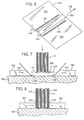
- FIG. 6 shows preparation of a book cover 140 for attachment to the crepe 120.
- the cover 140 is transported into the direction 142 relative to hot glue extrusion guns 144 to apply glue ribbon 146 along the inner surface 148 of cover 140 near the cover spine section 150.
- glue ribbons 146 are applied to the book cover 140 using a Slautterback KB30 melt unit modified to provide a ribbon extrusion as opposed to a bead, i.e., circular, extrusion. More particularly, the Slautterback melt unit is modified by nozzle replacement wherein replacement nozzles include a slit aperture for producing a ribbon extrusion approximately 0.254 cm. (0.100 inch) in width and 0.025 cm. (0.010 inch) in height.
- An acceptable material for the hot glue ribbons 146 is available from National Starch and Chemical Company under the product No. 70-3136. Hot glue ribbons 146 are positioned to engage the outer edges 152 (Fig. 5) of crepe 120.
- Figs. 7 and 8 illustrate assembly of book block 10, crepe 120 and cover 140 at a cover nipping station.
- the cover 140 attaches to crepe 120 by way of the glue ribbons 146.
- the crepe 120 attaches to book block 10 by way of the PUR 20b previously deposited on the book spine 14.
- the assembly of book block 10, crepe 120 and cover 140 come to rest against a base plate 160.
- a pair of side plates 162 move laterally inward toward the assembly as indicated by arrows 164.
- the cover 140 and crepe 120 fold up around the book block 10 as shown in Fig. 8.
- the hot glue ribbons 146 join the crepe 120 and cover 140 to complete the book binding process.
- the assembly may then be removed from the nipping station be for final curing.
- Fig. 9 is a block diagram illustrating process control of the PUR delivery system illustrated in FIGS. 1-4.
- gear 190 is part of, or is mechanically coupled to, the portion of the binding machinery responsible for transport of book block 10.
- the rotational speed of gear 190 is used to derive a book block 10 speed.
- Gear 192 mechanically couples to the gear 190 and, therefore, also rotates according to the speed of book block 10 through the binding machinery.
- a pulse generating device 194 couples to the shaft 196 which carries gear 192. Pulse generating device 194 thereby provides pulse data 198 representing the speed of book block 10.
- Pulse data 198 is delivered to a book speed calculation block 200 which converts pulse data 198 into speed data 202.
- a photo sensor 204 positioned adjacent the path of book block 10 provides position data 206 representing a given position at a given time for book block 10. Position data 206 and speed data 202 are delivered to a process control block 208.
- process control 208 determines the position of book block 10 at any given subsequent time.
- process control 208 has sufficient information to suitably control actuation of pneumatic cylinder 24. More particularly, process control 208 delivers a control signal 210 to a trough cylinder valve control block 212.
- PUR 20 FOG. 1
- PUR 20 is deposited upon the length of book spine 14 but omitting the first and last one-sixteenth inch length portion of book spine 14.
- Process control 208 suitably actuates pneumatic cylinder 24 to draw leading edge 22a (FIG. 1) away from roller 12 whereby the leading portion of the PUR on roller 12 coincides with the leading portion of book block 10. Furthermore, process control 208 actuates pneumatic cylinder 24 to then drive leading edge 22a back against roller 12 at such time that the trailing edge of PUR 20 upon roller 12 coincides with the trailing end of the book block 10. In this manner, the desired delivery of PUR 20 upon book spine 14 is achieved wherein the first one-sixteenth and last one-sixteenth inch of book spine 14 do not receive PUR 20.
- Process control 208 is further responsible for controlling the speed of PUR roller 12. More particularly, process control 208 utilizes speed data 202 to provide a control signal 214 for delivery to a PUR roller speed control block 216.
- the speed control signal 214 causes rotation of PUR roller 12 at a speed corresponding to the rotational speed of roller 22. More particularly, it has been found advantageous to provide an overspin relationship between the rotational speed of roller 12 and the rectilinear speed of book block 10.
- Process control 208 receives overspin input 218 corresponding to a desired overspin of roller 12 relative to the rectilinear speed of book block 10.
- the overspin of roller 12 is up to three percent greater than the rectilinear speed of book block 10.
- process control 208 accepts speed data 202 from book speed calculation block 200 and overspin input 218 to develop a suitable speed control signal 214 for presentation to PUR roller speed control block 216.
- the PUR roller 12 may be operated at a desired overspin speed relative to the travel of book block 10.
- Process control 208 also receives temperature information relative to rollers 12. More particularly, roller 12 temperature sense block 220 and roller 60 temperature sense block 222 provide process control 208 with the current temperature of rollers 12 and 60, respectively. Process control 208 then compares the current temperature of rollers 12 and 60 to a desired temperature for rollers 12 and 60 and provide suitable output signals to roller 12 temperature control block 224 and roller 60 temperature control block 226. Similarly, the temperature of trough 22 is maintained at the desired temperature by means of a trough 22 temperature sense 228 delivering the current temperature of trough 22 to process control 208, and a corresponding output signal from process control 208 to trough 22 temperature control 230. It should be understood that the control of temperature of rollers 12 and 60 and trough 22 may be achieved in conventional feed back control loop fashion.
- the volume of PUR 20 maintained upon the trough 22 is controlled by a differential temperature sensing method. Accordingly, temperature sense 80 block 232 and temperature sense 82 block 234 report the current output from temperature sensors 80 and 82, respectively. Process control 208 then provides an output signal to source 16 control block 236 for suitably maintaining the volume of PUR 20 on trough 22. More particularly, when the block 232 reports a higher temperature than the block 234, process control 208 causes block 236 to actuate source 16 to deliver additional PUR 20 upon trough 22 and until such time as sensor 82 reports substantially the same temperature as that of sensor 80.
- PUR adhesive in the manner described above has proven to be an advance in the field of book binding.
- the PUR adhesive is well adapted for fully securing the crepe 120 to the book back 14.
- the resulting book structure is very secure against normal usage. Due to the shape of the book block 10 resulting from previous cutting steps, however, it is difficult to fully integrate the PUR into a region at the edge of the book back 14 and the crepe 120. As a result, an undesirable gap sometimes exists between the book block 10 and the crepe 120. While no additional bonding of the book block 10 and crepe 120 is needed, it is desirable to close this gap in order to improve the appearance of the resulting product.
- FIG. 10 illustrates application of gap glue 300 to the book block 10 following application of PUR as described above and previous to attachment of the crepe 120.
- a rounded edge 302 of the book block 10 results from engagement of the cutting blade when forming the book block 10.
- a flared edge 304 of the book block 10, opposite the rounded edge 302, results from disengagement of the cutting blade.
- the crepe 120 is mounted as described above, the rounded edge 302 does not fully accept the PUR and a gap results at the interface of the crepe 120 and the rounded edge 302 of the book block 10. This gap is eliminated by application of gap glue 300 along the rounded edge 302 prior to attachment of the crepe 120.
- the side glue applicator 306 includes a heated tank 308 holding, in the preferred embodiment, National Starch and Chemical hot melt glue sold under the product name UNI-FLEX and product number 34-1207 as the gap glue 300.
- a heated roller 310 having an axis of rotation inclined at approximately 45 degrees, rests within the glue 300 of tank 308 and rotates in response to rotation of a drive gear 312.
- the structural and operational details of the side glue applicator 306 by Muller-Martini are known and will not be further described herein.
- the periphery of the roller 310 defines a flat portion 314 approximately one millimeter wide and delivers the glue 300 at the rounded edge 302 of the book block 10.
- a similar side glue applicator 306 arrangement may be used to apply glue at the flared edge 304 of the book block 10, but there is less need for gap glue 300 at the flared edge 304 of the book block 10.
- FIG. 11 illustrates in perspective the completed assembly of book block 10 and crepe 120, following use of the side glue applicator 306 and attachment of the crepe 120 as described above, with the front cover 320 of the book opened and exposing the interface 322 of the crepe 120 and the rounded edge 302.
- gap glue 300 by provision of gap glue 300 in the manner described, the resulting book structure has no gap at the interface 322 leaving the desirable appearance of a well constructed book.
Landscapes
- Business, Economics & Management (AREA)
- Engineering & Computer Science (AREA)
- Educational Administration (AREA)
- Educational Technology (AREA)
- Folding Of Thin Sheet-Like Materials, Special Discharging Devices, And Others (AREA)
- Coating Apparatus (AREA)
- Sheet Holders (AREA)
- Packages (AREA)
- Professional, Industrial, Or Sporting Protective Garments (AREA)
- Application Of Or Painting With Fluid Materials (AREA)
- Packaging Of Annular Or Rod-Shaped Articles, Wearing Apparel, Cassettes, Or The Like (AREA)
Applications Claiming Priority (3)
| Application Number | Priority Date | Filing Date | Title |
|---|---|---|---|
| US90/002949A US5154447B1 (en) | 1990-11-27 | 1991-09-09 | Binding for soft cover books |
| US756985 | 1991-09-09 | ||
| EP92308107A EP0535809B1 (de) | 1991-09-09 | 1992-09-08 | Einband für Bücher mit biegsamen Deckeln |
Related Parent Applications (1)
| Application Number | Title | Priority Date | Filing Date |
|---|---|---|---|
| EP92308107.9 Division | 1992-09-08 |
Publications (2)
| Publication Number | Publication Date |
|---|---|
| EP0749849A2 true EP0749849A2 (de) | 1996-12-27 |
| EP0749849A3 EP0749849A3 (de) | 1997-08-27 |
Family
ID=25045874
Family Applications (2)
| Application Number | Title | Priority Date | Filing Date |
|---|---|---|---|
| EP92308107A Expired - Lifetime EP0535809B1 (de) | 1991-09-09 | 1992-09-08 | Einband für Bücher mit biegsamen Deckeln |
| EP96202758A Withdrawn EP0749849A3 (de) | 1991-09-09 | 1992-09-08 | Ein Band für Bücher mit biegsamen Deckeln |
Family Applications Before (1)
| Application Number | Title | Priority Date | Filing Date |
|---|---|---|---|
| EP92308107A Expired - Lifetime EP0535809B1 (de) | 1991-09-09 | 1992-09-08 | Einband für Bücher mit biegsamen Deckeln |
Country Status (8)
| Country | Link |
|---|---|
| US (1) | US5154447B1 (de) |
| EP (2) | EP0535809B1 (de) |
| JP (2) | JP2625326B2 (de) |
| CN (2) | CN1075916A (de) |
| AT (1) | ATE153920T1 (de) |
| BR (1) | BR9203499A (de) |
| CA (1) | CA2077725A1 (de) |
| DE (1) | DE69220171D1 (de) |
Cited By (2)
| Publication number | Priority date | Publication date | Assignee | Title |
|---|---|---|---|---|
| EP0873882A1 (de) * | 1997-04-24 | 1998-10-28 | Kolbus GmbH & Co. KG | Vorrichtung zum maschinellen Auftragen von Klebstoff auf den Rücken von Buchblocks |
| EP1084864A1 (de) * | 1999-09-17 | 2001-03-21 | Grapha-Holding Ag | Leimwerk zum Auftragen eines Klebstoffes auf den Rücken oder angrenzende Bereiche eines vorbeigefürten Buchblockes. |
Families Citing this family (30)
| Publication number | Priority date | Publication date | Assignee | Title |
|---|---|---|---|---|
| US5693142A (en) * | 1993-03-26 | 1997-12-02 | Nordson Corporation | Wheel applicator device for applying adhesive, especially to the spines of books during bookbinding |
| US5456496A (en) * | 1994-06-20 | 1995-10-10 | K-Flex, Inc. | Lay-flat book binding |
| US5632853A (en) * | 1995-04-26 | 1997-05-27 | International Binding Corporation | Adhesive cartridge for a desktop book binder |
| EP0813979B1 (de) | 1996-06-19 | 2001-09-19 | H.B. Fuller Licensing & Financing, Inc. | Thermoplastische Polyurethane für Buchbinderei |
| US6672815B2 (en) * | 2000-05-15 | 2004-01-06 | Powis Parker Inc. | Apparatus and method of binding soft cover book |
| US6709727B1 (en) | 2000-10-06 | 2004-03-23 | Powis Parker Inc. | Bookbinding structure and method |
| US7351024B2 (en) * | 2002-10-02 | 2008-04-01 | Powis Parker Inc. | Apparatus and method for binding a book |
| US7134822B2 (en) * | 2002-10-02 | 2006-11-14 | Powis Parker Inc. | Guide apparatus for use in making a hardcover book |
| US7246981B2 (en) * | 2002-10-02 | 2007-07-24 | Powis Parker, Inc. | Apparatus and method for making hardcover book |
| US20040066029A1 (en) * | 2002-10-02 | 2004-04-08 | Parker Kevin P. | Method of making a hardcover book and hardcover apparatus |
| US7588066B2 (en) * | 2004-03-15 | 2009-09-15 | Powis Parker Inc. | Binder strip cassette |
| US7153076B2 (en) * | 2004-10-19 | 2006-12-26 | Powis Parker Inc. | Method of applying a wrap sheet to a book hardcover and related guide apparatus |
| US7452172B2 (en) * | 2004-11-30 | 2008-11-18 | Powis Parker Inc. | Method of making and applying a hardcover over-wrap and guide apparatus |
| US20060198719A1 (en) * | 2005-03-07 | 2006-09-07 | Parker Kevin P | Apparatus and method of applying a hardcover assembly to a bound stack |
| US20070216153A1 (en) * | 2006-03-06 | 2007-09-20 | Parker Kevin P | Bound book having hardcover and method of making same |
| JP4326543B2 (ja) * | 2006-04-27 | 2009-09-09 | ホリゾン・インターナショナル株式会社 | 無線綴製本処理装置 |
| JP2008114476A (ja) * | 2006-11-06 | 2008-05-22 | Konica Minolta Business Technologies Inc | 製本装置及び画像形成システム |
| DE102007038558A1 (de) * | 2007-08-16 | 2009-02-19 | Heidelberger Druckmaschinen Ag | Klebebinder |
| JP2010058440A (ja) * | 2008-09-05 | 2010-03-18 | Kyodo Seiki:Kk | 糊付装置 |
| DE102010030807B4 (de) * | 2010-07-01 | 2015-09-03 | Kugler-Womako Gmbh | Verfahren und Einrichtung zum Kaschieren eines Substratträgers |
| CN102390195A (zh) * | 2011-11-11 | 2012-03-28 | 于林义 | 叠置物品及其制造工艺 |
| EP2634007B1 (de) * | 2012-02-29 | 2014-07-30 | Müller Martini Holding AG | Verfahren und Vorrichtung zum Wechseln einer Klebstoff-Auftragswalze |
| JP5929433B2 (ja) * | 2012-04-03 | 2016-06-08 | コニカミノルタ株式会社 | 製本装置、及び製本システム |
| JP6127374B2 (ja) * | 2012-04-03 | 2017-05-17 | コニカミノルタ株式会社 | 製本装置、及び製本システム |
| CN102795018B (zh) * | 2012-09-10 | 2014-08-13 | 黄力树 | 喷胶式无线胶装机的胶罐 |
| CN104191856B (zh) * | 2014-08-27 | 2016-05-04 | 黄力树 | Pur胶筒熔胶系统 |
| WO2018193523A1 (ja) * | 2017-04-18 | 2018-10-25 | ホリゾン・インターナショナル株式会社 | 製本装置 |
| CN107554119A (zh) * | 2017-08-25 | 2018-01-09 | 南通成山高分子材料有限公司 | 一种书本胶装工艺 |
| KR102093908B1 (ko) * | 2018-02-21 | 2020-03-26 | 애디언트코리아 주식회사 | 습기 경화성 폴리우레탄 핫멜트 접착제를 이용한 저온 핫멜트 카시트 제조공법 |
| CN115284765B (zh) * | 2022-06-22 | 2023-08-01 | 安徽宣城海峰印刷包装有限公司 | 一种用于书本印刷品的刷胶装置 |
Family Cites Families (12)
| Publication number | Priority date | Publication date | Assignee | Title |
|---|---|---|---|---|
| US951436A (en) * | 1909-02-04 | 1910-03-08 | James Pott & Co | Binding for books. |
| US998283A (en) * | 1910-03-08 | 1911-07-18 | Charles R Duryea | Binding for books. |
| DE864248C (de) * | 1942-11-15 | 1953-01-22 | J C Koenig & Ebhardt | Buch, insbesondere Geschaeftsbuch |
| US2605739A (en) * | 1947-08-26 | 1952-08-05 | Florez Company Inc De | Machine for applying adhesive to the binding edges of books |
| DE1028534B (de) * | 1954-02-23 | 1958-04-24 | Rahdener Maschf August | Einrichtung fuer Bucheinhaengemaschinen zum Auftragen einer uebernormal starken Leimschicht im Bereich der dem Buchruecken benachbarten Raender des Buchblocks |
| CH405233A (de) * | 1964-06-23 | 1966-01-15 | Thouvenin & Co | Maschine zum Klebebinden von Buchblocks |
| US3437506A (en) * | 1964-12-28 | 1969-04-08 | Joanna Western Mills Co | Bookbinding tape |
| FI61429B (fi) * | 1979-05-11 | 1982-04-30 | Kustannus Oy Otava | Haeftad bok med mjuka paermar och foerfarande foer dess tillverkning |
| FI61657C (fi) * | 1981-05-05 | 1982-09-10 | Pentti Sallinen | Bladaemnen med mjuka paermar och saett att tillverka detsamma |
| DE3502733C1 (de) * | 1985-01-28 | 1986-02-13 | Kolbus GmbH & Co KG, 4993 Rahden | Verfahren zum maschinellen Auftragen von Klebstoff auf Buchblockruecken |
| DE3815159A1 (de) * | 1988-03-09 | 1989-09-21 | Rido Richard Dohse & Sohn | Vorrichtung zum auftrag von vorgeschmolzenen polyurethan-klebstoffen |
| DE3811133A1 (de) * | 1988-03-16 | 1989-09-28 | Helmut Nossek | Klebegebundene gelenkbroschuere (paperback) mit flexiblem buchruecken |
-
1991
- 1991-09-09 US US90/002949A patent/US5154447B1/en not_active Expired - Fee Related
-
1992
- 1992-09-08 AT AT92308107T patent/ATE153920T1/de not_active IP Right Cessation
- 1992-09-08 EP EP92308107A patent/EP0535809B1/de not_active Expired - Lifetime
- 1992-09-08 EP EP96202758A patent/EP0749849A3/de not_active Withdrawn
- 1992-09-08 DE DE69220171T patent/DE69220171D1/de not_active Expired - Lifetime
- 1992-09-08 CA CA002077725A patent/CA2077725A1/en not_active Abandoned
- 1992-09-09 BR BR929203499A patent/BR9203499A/pt not_active Application Discontinuation
- 1992-09-09 JP JP4240434A patent/JP2625326B2/ja not_active Expired - Lifetime
- 1992-09-09 CN CN92111391A patent/CN1075916A/zh active Pending
-
1994
- 1994-05-25 CN CN94105124A patent/CN1098683A/zh active Pending
- 1994-06-09 JP JP6127535A patent/JP2625383B2/ja not_active Expired - Lifetime
Cited By (3)
| Publication number | Priority date | Publication date | Assignee | Title |
|---|---|---|---|---|
| EP0873882A1 (de) * | 1997-04-24 | 1998-10-28 | Kolbus GmbH & Co. KG | Vorrichtung zum maschinellen Auftragen von Klebstoff auf den Rücken von Buchblocks |
| EP1084864A1 (de) * | 1999-09-17 | 2001-03-21 | Grapha-Holding Ag | Leimwerk zum Auftragen eines Klebstoffes auf den Rücken oder angrenzende Bereiche eines vorbeigefürten Buchblockes. |
| US6503040B1 (en) | 1999-09-17 | 2003-01-07 | Grapha Holding Ag | Applicator for applying adhesive to the spine or adjoining regions of a book block guided past the applicator |
Also Published As
| Publication number | Publication date |
|---|---|
| EP0535809B1 (de) | 1997-06-04 |
| EP0535809A1 (de) | 1993-04-07 |
| JPH08118839A (ja) | 1996-05-14 |
| EP0749849A3 (de) | 1997-08-27 |
| CN1075916A (zh) | 1993-09-08 |
| DE69220171D1 (de) | 1997-07-10 |
| CN1098683A (zh) | 1995-02-15 |
| JP2625383B2 (ja) | 1997-07-02 |
| JPH05201170A (ja) | 1993-08-10 |
| US5154447A (en) | 1992-10-13 |
| US5154447B1 (en) | 1993-10-19 |
| JP2625326B2 (ja) | 1997-07-02 |
| ATE153920T1 (de) | 1997-06-15 |
| BR9203499A (pt) | 1993-04-20 |
| CA2077725A1 (en) | 1993-03-10 |
Similar Documents
| Publication | Publication Date | Title |
|---|---|---|
| EP0535809B1 (de) | Einband für Bücher mit biegsamen Deckeln | |
| US5250318A (en) | Method for applying adhesive for book binding | |
| US10435589B2 (en) | Device and method for applying adhesive to a substrate | |
| JPH02103144A (ja) | 材料の層を供給する装置と方法 | |
| JPH06211224A (ja) | ラベルの不整合を防止する圧力適用器を使用した小型円筒物品にラベルを適用する装置および方法 | |
| JPS63242638A (ja) | 印刷開始前に輪転印刷機のインキ装置に本刷りに近いインキ配分を一定に生じさせる方法 | |
| US5538570A (en) | Apparatus and method for applying adhesive for book binding and independent adhesive roller speed control | |
| US5417797A (en) | Apparatus and method for applying adhesive for book binding | |
| US6389782B1 (en) | Method and apparatus for wrapping elongated article | |
| US20150337426A1 (en) | Apparatus for applying a hot-melt adhesive to a substrate | |
| US4249984A (en) | Gumming apparatus | |
| US4363288A (en) | Device for applying a coating layer to a strip of continuously moving material | |
| US4480582A (en) | Adhesive applying apparatus | |
| US4154640A (en) | Stencil tabbing machine | |
| DE60106852T2 (de) | Verfahren, Gerät und Anlage zum Gummieren von Gegenständen | |
| US3996890A (en) | Apparatus for forming and transferring thin liquid layers | |
| US2189214A (en) | Icing of or the application of cream or the like to biscuits | |
| US5000086A (en) | Method for applying a liquid release agent on a cheese | |
| US4452172A (en) | Gummer for cigarette filter attachment machines | |
| JPH02239991A (ja) | 製本用糊塗布装置 | |
| US4505198A (en) | Apparatus and method for applying printed material to a cylindrical object | |
| AU674785B2 (en) | Slot coating die configuration | |
| JPS6218284Y2 (de) | ||
| DE102009006992A1 (de) | Vorrichtung zum Auftragen einer Flüssigkeit entlang einer Biegelinie | |
| EP1184088B1 (de) | Beschichtungsverfahren und Vorrichtung |
Legal Events
| Date | Code | Title | Description |
|---|---|---|---|
| PUAI | Public reference made under article 153(3) epc to a published international application that has entered the european phase |
Free format text: ORIGINAL CODE: 0009012 |
|
| AC | Divisional application: reference to earlier application |
Ref document number: 535809 Country of ref document: EP |
|
| AK | Designated contracting states |
Kind code of ref document: A2 Designated state(s): AT CH DE ES GB IE LI NL |
|
| PUAL | Search report despatched |
Free format text: ORIGINAL CODE: 0009013 |
|
| AK | Designated contracting states |
Kind code of ref document: A3 Designated state(s): AT CH DE ES GB IE LI NL |
|
| STAA | Information on the status of an ep patent application or granted ep patent |
Free format text: STATUS: THE APPLICATION IS DEEMED TO BE WITHDRAWN |
|
| 18D | Application deemed to be withdrawn |
Effective date: 19980331 |