EP0749871B1 - Vorrichtung zur Befestigung einer Rückleuchteneinheit für Kraftfahrzeuge - Google Patents
Vorrichtung zur Befestigung einer Rückleuchteneinheit für Kraftfahrzeuge Download PDFInfo
- Publication number
- EP0749871B1 EP0749871B1 EP96109666A EP96109666A EP0749871B1 EP 0749871 B1 EP0749871 B1 EP 0749871B1 EP 96109666 A EP96109666 A EP 96109666A EP 96109666 A EP96109666 A EP 96109666A EP 0749871 B1 EP0749871 B1 EP 0749871B1
- Authority
- EP
- European Patent Office
- Prior art keywords
- opening
- lamp unit
- metal panel
- transparent member
- panel
- Prior art date
- Legal status (The legal status is an assumption and is not a legal conclusion. Google has not performed a legal analysis and makes no representation as to the accuracy of the status listed.)
- Expired - Lifetime
Links
- 239000002184 metal Substances 0.000 claims description 15
- 230000002093 peripheral effect Effects 0.000 claims description 4
- 238000010276 construction Methods 0.000 description 1
- 230000000694 effects Effects 0.000 description 1
- 239000000463 material Substances 0.000 description 1
- 238000000034 method Methods 0.000 description 1
- 239000007787 solid Substances 0.000 description 1
Images

Classifications
-
- B—PERFORMING OPERATIONS; TRANSPORTING
- B60—VEHICLES IN GENERAL
- B60Q—ARRANGEMENT OF SIGNALLING OR LIGHTING DEVICES, THE MOUNTING OR SUPPORTING THEREOF OR CIRCUITS THEREFOR, FOR VEHICLES IN GENERAL
- B60Q1/00—Arrangement of optical signalling or lighting devices, the mounting or supporting thereof or circuits therefor
- B60Q1/26—Arrangement of optical signalling or lighting devices, the mounting or supporting thereof or circuits therefor the devices being primarily intended to indicate the vehicle, or parts thereof, or to give signals, to other traffic
- B60Q1/2619—Arrangement of optical signalling or lighting devices, the mounting or supporting thereof or circuits therefor the devices being primarily intended to indicate the vehicle, or parts thereof, or to give signals, to other traffic built in the vehicle body
- B60Q1/2623—Details of the fastening means
- B60Q1/2626—Screw-nut fasteners
-
- B—PERFORMING OPERATIONS; TRANSPORTING
- B60—VEHICLES IN GENERAL
- B60Q—ARRANGEMENT OF SIGNALLING OR LIGHTING DEVICES, THE MOUNTING OR SUPPORTING THEREOF OR CIRCUITS THEREFOR, FOR VEHICLES IN GENERAL
- B60Q1/00—Arrangement of optical signalling or lighting devices, the mounting or supporting thereof or circuits therefor
- B60Q1/26—Arrangement of optical signalling or lighting devices, the mounting or supporting thereof or circuits therefor the devices being primarily intended to indicate the vehicle, or parts thereof, or to give signals, to other traffic
- B60Q1/2619—Arrangement of optical signalling or lighting devices, the mounting or supporting thereof or circuits therefor the devices being primarily intended to indicate the vehicle, or parts thereof, or to give signals, to other traffic built in the vehicle body
- B60Q1/2653—Arrangement of optical signalling or lighting devices, the mounting or supporting thereof or circuits therefor the devices being primarily intended to indicate the vehicle, or parts thereof, or to give signals, to other traffic built in the vehicle body with arrangement for sealing the device with respect to the vehicle body, or for concealing gaps between the device and the vehicle body
Definitions
- the present invention concerns a device for fixing a rear lamp unit to a motor vehicle, particularly a motor car, of the kind defined in the preamble of claims 1 and 2.
- a device of this kind is known from DE-A-20 01 708.
- the means for centring and locking the lamp unit in a corresponding opening of a motor vehicle body panel comprise a plurality of resilient peripheral members integral with the lamp housing body, which are provided with respective stepped surfaces adapted to interferingly engage with the edge of said opening.
- a circumferential lip of the lamp housing body is adapted to be brought in abutment against the outer surface of the panel around said opening.
- the object of the present invention is to provide an improved device for fixing a rear lamp unit to a motor vehicle, particularly a motor car, which is of simple construction and is inexpensive.
- the present invention achieves the aforesaid objects by virtue of a device for fixing a rear lamp unit to a motor vehicle, particularly a motor car, having the characteristics specifically referred to in the following claims.
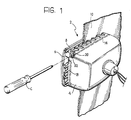
- the reference numeral 2 indicates in its entirety a first embodiment of a lamp unit provided with the device for centring and fixing it to the vehicle body.
- the lamp unit 2 includes a lamp body 4, a transparent member 6 and a gasket 8.
- the lamp body 4 is positioned in an opening in the metal panel 10; the outer edge of the lamp body 4 facing the panel 10 is provided with adjacent projections 12 which define therebetween parallel passages inclined with respect to the plane of the panel 10.
- a strip 14 of plastically deformable material on the peripheral edge of the lamp body 4 facing the panel 10 is inserted in a channel R formed in the peripheral edge of the lamp body 4 ( Figure 3) and includes inclined lettral teeth or fingers 16, each tooth being interposed in the passage defined between two adjacent projections 12.
- the strip 14 is permanently fixed at one end 18 to the lamp body 4, and is attached at its other end 20 to a threaded sleeve (not shown) attached to the lamp body 4 and engageable by a screw 22.
- the lamp unit 2 is securely fixed to the motor vehicle body, without needing projections in the back of the vehicle body.
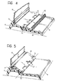
- FIG. 4 A second embodiment of the device according to the invention is illustrated in Figures 4 and 5, in which equivalent or similar details to those previously described are indicated with the same reference numerals.
- pivotable elements indicated 50 are disposed along the periphery of the lamp body 4 and are pivoted thereto by hinges 52 having an axis of rotation substantially parallel to the panel to which the lamp body 4 is to be fixed.
- the end part of each of the pivotable elements 50 is shaped as a hook provided with knurling 60.
- the lamp body 4 is fitted to the panel 10 as follows. After having positioned the lamp body 4, the pivotable elements 50 are pivoted about the hinges 52 to bring their curved ends into contact with the panel 10, and the lamp unit 2 is locked by force against the panel 10, this also being by virtue of the "gripping" effect of the knurling 60.
- the strip 14 which is formed as a single piece in the embodiments illustrated, may instead be formed as two or more pieces, each being anchored to the lamp body 4 and provided with a tensioning screw 22.
Landscapes
- Engineering & Computer Science (AREA)
- Mechanical Engineering (AREA)
- Lighting Device Outwards From Vehicle And Optical Signal (AREA)
- Fastening Of Light Sources Or Lamp Holders (AREA)
Claims (2)
- Vorrichtung zum Befestigen einer Rückleuchteneinheit (2) an ein Kraftfahrzeug, insbesondere einen Kraftwagen, in einer in einer Kraftfahrzeugkarosserie-Wand (10) gebildeten Öffnung, wobei die Leuchteneinheit (2) einen Leuchtenhauptteil (4) einschließt, der bei Verwendung dazu bestimmt ist, innerhalb der Öffnung positioniert zu werden, und ein durchsichtiges Bauglied (6) einschließt, das dazu bestimmt ist, außerhalb der Öffnung positioniert zu werden, wobei die Öffnung einen Querschnitt aufweist, der etwas größer als der eines Zwischenteils der Leuchteneinheit (2) ist, und wobei die Vorrichtung Mittel, die an der äußeren Peripherie des Leuchtenhauptteils (4) angeordnet sind, und zwar an der der Metallwand (10) zugewandten Seite, zum Zentrieren und Fixieren der Leuchteneinheit (2) gegen die äußeren Kanten der Öffnung der Metallwand (10) einschließt,
dadurch gekennzeichnet, dass sie ferner eine Dichtung (8) einschließt, die dazu bestimmt ist, zwischen der Kante des durchsichtigen Bauglieds (6) und der Kante der Öffnung in der dem durchsichtigen Bauglied (6) zugewandten Metallwand (10) angeordnet zu werden, wobei die Öffnung einen Querschnitt aufweist, der substanziell kleiner als der des durchsichtigen Bauglieds (6) ist, wobei die Mittel zum Zentrieren und Fixieren der Leuchteneinheit (2) gegen die Kanten der Öffnung der Metallwand (10) eine Mehrzahl an Fortsätzen (12) am äußeren peripheren Teil des Leuchtenhauptteils (4), die im Einsatz der Innenfläche der Kanten der Öffnung der Metallwand (10) zugewandt sind und die dazwischen parallele, zur Wand (10) geneigte Durchgänge definieren, sowie einen Streifen (14) einschließen, der an der Peripherie des Leuchtenhauptteils (4) angeordnet ist, welcher Streifen ebenfalls der Innenfläche der Kanten der Öffnung der Metallwand (10) zugewandt ist, und der eingesetzt ist in einem Kanal (R), der in der Peripherie des Leuchtenhauptteils (4) gebildet ist, wobei der Streifen (14) geneigte seitliche Zähne (16) aufweist, die sich jeweils in einen der Durchgänge zwischen zwei benachbarten Fortsätzen (12) erstrecken, und wobei die Anordnung so ist, dass bei einem Ziehen des Streifens (14) sich dessen Zähne (16) die Leuchteneinheit (2) gegen die Kanten der Öffnung der Metallwand (10) pressend im Durchgang hin zur Metallwand (10) bewegen. - Vorrichtung zum Befestigen einer Rückleuchteneinheit (2) an ein Kraftfahrzeug, insbesondere einen Kraftwagen, in einer in einer Kraftfahrzeugkarosserie-Wand (10) gebildeten Öffnung, wobei die Leuchteneinheit (2) einen Leuchtenhauptteil (4) einschließt, der bei Verwendung dazu bestimmt ist, innerhalb der Öffnung positioniert zu werden, und ein durchsichtiges Bauglied (6) einschließt, das dazu bestimmt ist, außerhalb der Öffnung positioniert zu werden, wobei die Öffnung einen Querschnitt aufweist, der etwas größer als der eines Zwischenteils der Leuchteneinheit (2) ist, und wobei die Vorrichtung Mittel, die an der äußeren Peripherie des Leuchtenhauptteils (4) angeordnet sind, und zwar an der der Metallwand (10) zugewandten Seite, zum Zentrieren und Fixieren der Leuchteneinheit (2) gegen die äußeren Kanten der Öffnung der Metallwand (10) einschließt,
dadurch gekennzeichnet, dass sie ferner eine Dichtung (8) einschließt, die dazu bestimmt ist, zwischen der Kante des durchsichtigen Bauglieds (6) und der Kante der Öffnung in der dem durchsichtigen Bauglied (6) zugewandten Metallwand (10) angeordnet zu werden, wobei die Öffnung einen Querschnitt aufweist, der substanziell kleiner als der des durchsichtigen Bauglieds (6) ist, und wobei die Mittel zum Zentrieren und Fixieren der Leuchteneinheit (2) gegen die Kanten der Öffnung der Metallwand (10) Gelenkelemente (50) am Leuchtenhauptteil (4) einschließen, die auf eine Rotation hin interferierend mit der Innenseite der Kanten der Öffnung der Metallwand (10) in Eingriff kommen.
Applications Claiming Priority (2)
| Application Number | Priority Date | Filing Date | Title |
|---|---|---|---|
| IT95TO000520A IT1276430B1 (it) | 1995-06-22 | 1995-06-22 | Dispositivo a fissaggio di un gruppo ottico posterire per autoveicoli particolarmente autovetture. |
| ITTO950520 | 1995-06-22 |
Publications (3)
| Publication Number | Publication Date |
|---|---|
| EP0749871A2 EP0749871A2 (de) | 1996-12-27 |
| EP0749871A3 EP0749871A3 (de) | 1997-11-05 |
| EP0749871B1 true EP0749871B1 (de) | 2001-10-24 |
Family
ID=11413666
Family Applications (1)
| Application Number | Title | Priority Date | Filing Date |
|---|---|---|---|
| EP96109666A Expired - Lifetime EP0749871B1 (de) | 1995-06-22 | 1996-06-17 | Vorrichtung zur Befestigung einer Rückleuchteneinheit für Kraftfahrzeuge |
Country Status (4)
| Country | Link |
|---|---|
| EP (1) | EP0749871B1 (de) |
| DE (1) | DE69616165T2 (de) |
| ES (1) | ES2164805T3 (de) |
| IT (1) | IT1276430B1 (de) |
Families Citing this family (4)
| Publication number | Priority date | Publication date | Assignee | Title |
|---|---|---|---|---|
| DE102004049319A1 (de) * | 2004-10-09 | 2006-04-20 | Hella Kgaa Hueck & Co. | Vorrichtung zur Befestigung einer Leuchteinheit und Montageverfahren |
| DE202005006376U1 (de) * | 2005-04-21 | 2005-06-16 | Fer Fahrzeugelektrik Gmbh | Fahrzeugleuchte mit einem im Einbauzustand lösbaren Bauteil |
| DE102006005792B4 (de) | 2006-02-07 | 2018-04-26 | Fachhochschule Aachen | Hochfrequenzzündanlage für Kraftfahrzeuge |
| IT1397982B1 (it) * | 2010-02-05 | 2013-02-04 | Olsa Spa | Luce di veicolo con sistema di bloccaggio a molle. |
Family Cites Families (1)
| Publication number | Priority date | Publication date | Assignee | Title |
|---|---|---|---|---|
| AU1015670A (en) * | 1969-01-16 | 1971-07-15 | Dominion Auto Accessories Limited | Improvements in lamp housing |
-
1995
- 1995-06-22 IT IT95TO000520A patent/IT1276430B1/it active IP Right Grant
-
1996
- 1996-06-17 EP EP96109666A patent/EP0749871B1/de not_active Expired - Lifetime
- 1996-06-17 DE DE69616165T patent/DE69616165T2/de not_active Expired - Fee Related
- 1996-06-17 ES ES96109666T patent/ES2164805T3/es not_active Expired - Lifetime
Also Published As
| Publication number | Publication date |
|---|---|
| ITTO950520A0 (it) | 1995-06-22 |
| EP0749871A2 (de) | 1996-12-27 |
| ES2164805T3 (es) | 2002-03-01 |
| EP0749871A3 (de) | 1997-11-05 |
| DE69616165T2 (de) | 2002-06-06 |
| ITTO950520A1 (it) | 1996-12-22 |
| IT1276430B1 (it) | 1997-10-31 |
| DE69616165D1 (de) | 2001-11-29 |
Similar Documents
| Publication | Publication Date | Title |
|---|---|---|
| US5716154A (en) | Attachment device | |
| JPH0114449B2 (de) | ||
| EP1039195A1 (de) | Schelle zur Befestigung eines rohrförmigen Körpers | |
| FR2688452A1 (fr) | Dispositif d'etancheite a element profile tubulaire, notamment pour vehicule automobile. | |
| US20050028329A1 (en) | Clamp | |
| USD372694S (en) | Motorcycle tire | |
| FR2529268A1 (fr) | Agrafe de fixation de conduites, cables, etc., sur des rebords de toles | |
| US6892427B2 (en) | Retaining clips | |
| USD366232S (en) | Automobile tire | |
| EP1070639B1 (de) | Verbessertes Kraftfahrzeugfrontteil | |
| EP0749871A2 (de) | Vorrichtung zur Befestigung einer Rückleuchteneinheit für Kraftfahrzeuge | |
| JP3843137B2 (ja) | ホースクリップとそれのための固定用部材 | |
| CA2169698A1 (en) | Clamping band | |
| US20060120796A1 (en) | Part positioner and part pressing member | |
| BE1012418A6 (fr) | Appareil de montage pour la fixation serrante de bandes profilees. | |
| FR2530301A1 (fr) | Dispositif permettant la fixation de tubes et/ou de cables sur le bord d'une tole | |
| EP0648943B1 (de) | Befestigungsvorrichtung mit schneller und dreidimensionaler Einstellung irgend eines Werkstücks auf einem Träger | |
| EP0029391A1 (de) | Zierleiste zur Abdeckung von Scheibenrändern | |
| JPH03113105A (ja) | ブーツクランプ | |
| EP2168810B1 (de) | Lighting or signalling device comprising means for fixing by an expansion pin | |
| EP2168811B1 (de) | Lighting or signalling device for an automobile comprising a fixing element equipped with an elastically deformable element | |
| KR200177972Y1 (ko) | 트렁크리드 록킹부재의 패드 장착구조 | |
| FR2626628A1 (fr) | Agrafe plastique notamment pour piece de revetement d'une paroi de vehicule | |
| FR2624664A1 (fr) | Dispositif d'amarrage de cable pour entree de cable | |
| FR2640539A1 (fr) | Douille de vissage |
Legal Events
| Date | Code | Title | Description |
|---|---|---|---|
| PUAI | Public reference made under article 153(3) epc to a published international application that has entered the european phase |
Free format text: ORIGINAL CODE: 0009012 |
|
| AK | Designated contracting states |
Kind code of ref document: A2 Designated state(s): DE ES FR GB SE |
|
| PUAL | Search report despatched |
Free format text: ORIGINAL CODE: 0009013 |
|
| AK | Designated contracting states |
Kind code of ref document: A3 Designated state(s): DE ES FR GB SE |
|
| 17P | Request for examination filed |
Effective date: 19980418 |
|
| 17Q | First examination report despatched |
Effective date: 19990810 |
|
| EUG | Se: european patent has lapsed | ||
| GRAG | Despatch of communication of intention to grant |
Free format text: ORIGINAL CODE: EPIDOS AGRA |
|
| RAP1 | Party data changed (applicant data changed or rights of an application transferred) |
Owner name: FIAT AUTO S.P.A. |
|
| GRAG | Despatch of communication of intention to grant |
Free format text: ORIGINAL CODE: EPIDOS AGRA |
|
| GRAH | Despatch of communication of intention to grant a patent |
Free format text: ORIGINAL CODE: EPIDOS IGRA |
|
| GRAH | Despatch of communication of intention to grant a patent |
Free format text: ORIGINAL CODE: EPIDOS IGRA |
|
| GRAA | (expected) grant |
Free format text: ORIGINAL CODE: 0009210 |
|
| AK | Designated contracting states |
Kind code of ref document: B1 Designated state(s): DE ES FR GB SE |
|
| REF | Corresponds to: |
Ref document number: 69616165 Country of ref document: DE Date of ref document: 20011129 |
|
| REG | Reference to a national code |
Ref country code: GB Ref legal event code: IF02 |
|
| REG | Reference to a national code |
Ref country code: ES Ref legal event code: FG2A Ref document number: 2164805 Country of ref document: ES Kind code of ref document: T3 |
|
| ET | Fr: translation filed | ||
| PLBE | No opposition filed within time limit |
Free format text: ORIGINAL CODE: 0009261 |
|
| STAA | Information on the status of an ep patent application or granted ep patent |
Free format text: STATUS: NO OPPOSITION FILED WITHIN TIME LIMIT |
|
| 26N | No opposition filed | ||
| PGFP | Annual fee paid to national office [announced via postgrant information from national office to epo] |
Ref country code: SE Payment date: 20060502 Year of fee payment: 11 |
|
| PGFP | Annual fee paid to national office [announced via postgrant information from national office to epo] |
Ref country code: ES Payment date: 20060508 Year of fee payment: 11 |
|
| PGFP | Annual fee paid to national office [announced via postgrant information from national office to epo] |
Ref country code: GB Payment date: 20060516 Year of fee payment: 11 |
|
| PGFP | Annual fee paid to national office [announced via postgrant information from national office to epo] |
Ref country code: DE Payment date: 20060523 Year of fee payment: 11 |
|
| PGFP | Annual fee paid to national office [announced via postgrant information from national office to epo] |
Ref country code: FR Payment date: 20060630 Year of fee payment: 11 |
|
| EUG | Se: european patent has lapsed | ||
| GBPC | Gb: european patent ceased through non-payment of renewal fee |
Effective date: 20070617 |
|
| REG | Reference to a national code |
Ref country code: FR Ref legal event code: ST Effective date: 20080229 |
|
| PG25 | Lapsed in a contracting state [announced via postgrant information from national office to epo] |
Ref country code: DE Free format text: LAPSE BECAUSE OF NON-PAYMENT OF DUE FEES Effective date: 20080101 |
|
| PG25 | Lapsed in a contracting state [announced via postgrant information from national office to epo] |
Ref country code: GB Free format text: LAPSE BECAUSE OF NON-PAYMENT OF DUE FEES Effective date: 20070617 |
|
| PG25 | Lapsed in a contracting state [announced via postgrant information from national office to epo] |
Ref country code: SE Free format text: LAPSE BECAUSE OF NON-PAYMENT OF DUE FEES Effective date: 20070618 |
|
| REG | Reference to a national code |
Ref country code: ES Ref legal event code: FD2A Effective date: 20070618 |
|
| PG25 | Lapsed in a contracting state [announced via postgrant information from national office to epo] |
Ref country code: FR Free format text: LAPSE BECAUSE OF NON-PAYMENT OF DUE FEES Effective date: 20070702 |
|
| PG25 | Lapsed in a contracting state [announced via postgrant information from national office to epo] |
Ref country code: ES Free format text: LAPSE BECAUSE OF NON-PAYMENT OF DUE FEES Effective date: 20070618 |