EP0749879A1 - Trichterklappen für Eisenbahn-Schüttgutwagen und Positioniersystem - Google Patents
Trichterklappen für Eisenbahn-Schüttgutwagen und Positioniersystem Download PDFInfo
- Publication number
- EP0749879A1 EP0749879A1 EP96401329A EP96401329A EP0749879A1 EP 0749879 A1 EP0749879 A1 EP 0749879A1 EP 96401329 A EP96401329 A EP 96401329A EP 96401329 A EP96401329 A EP 96401329A EP 0749879 A1 EP0749879 A1 EP 0749879A1
- Authority
- EP
- European Patent Office
- Prior art keywords
- hopper
- doors
- ballast
- outlet
- door
- Prior art date
- Legal status (The legal status is an assumption and is not a legal conclusion. Google has not performed a legal analysis and makes no representation as to the accuracy of the status listed.)
- Withdrawn
Links
- 239000012530 fluid Substances 0.000 description 11
- 230000003137 locomotive effect Effects 0.000 description 7
- 239000000463 material Substances 0.000 description 7
- 238000000429 assembly Methods 0.000 description 5
- 230000000712 assembly Effects 0.000 description 5
- 238000010276 construction Methods 0.000 description 3
- 230000001276 controlling effect Effects 0.000 description 3
- 239000004575 stone Substances 0.000 description 3
- 230000005540 biological transmission Effects 0.000 description 2
- 239000013590 bulk material Substances 0.000 description 2
- 238000000151 deposition Methods 0.000 description 2
- 238000000034 method Methods 0.000 description 2
- 230000007935 neutral effect Effects 0.000 description 2
- 229910000831 Steel Inorganic materials 0.000 description 1
- 230000009471 action Effects 0.000 description 1
- 239000000356 contaminant Substances 0.000 description 1
- 230000008878 coupling Effects 0.000 description 1
- 238000010168 coupling process Methods 0.000 description 1
- 238000005859 coupling reaction Methods 0.000 description 1
- 238000007599 discharging Methods 0.000 description 1
- 230000007246 mechanism Effects 0.000 description 1
- 230000008569 process Effects 0.000 description 1
- 230000001105 regulatory effect Effects 0.000 description 1
- 230000011664 signaling Effects 0.000 description 1
- 230000005477 standard model Effects 0.000 description 1
- 239000010959 steel Substances 0.000 description 1
- 239000000126 substance Substances 0.000 description 1
Images


Classifications
-
- B—PERFORMING OPERATIONS; TRANSPORTING
- B61—RAILWAYS
- B61D—BODY DETAILS OR KINDS OF RAILWAY VEHICLES
- B61D7/00—Hopper cars
- B61D7/06—Hopper cars with openings capable of discharging both between and outside the wheels
-
- B—PERFORMING OPERATIONS; TRANSPORTING
- B61—RAILWAYS
- B61D—BODY DETAILS OR KINDS OF RAILWAY VEHICLES
- B61D7/00—Hopper cars
- B61D7/14—Adaptations of hopper elements to railways
- B61D7/16—Closure elements for discharge openings
- B61D7/24—Opening or closing means
- B61D7/30—Opening or closing means controlled by means external to cars
Definitions
- This invention relates to a railroad car hopper door system, and more particularly, to ballast gates with hopper doors for mounting along the centerline of a railroad hopper car.
- Each hopper door in the ballast gates is provided with a drive system for opening and closing the hopper door.
- a remote control system is provided to selectively control the ballast discharge to the left, center or right of the rails.
- the present invention utilizes the pneumatic power supply furnished by the locomotive to the railroad hopper cars.
- the pneumatic power is converted to hydraulic power to drive the hopper doors when opening and closing the doors to selectively discharge ballast material.
- other power sources and drive systems may be mounted on the hopper cars to provide power to open and close the hopper doors.
- the remote control transmitter and receiver included as part of the system provide an accurate and economical means for achieving remote operating capabilities. Radio frequency, infrared, or other similar remote control systems may also be used to control the hopper doors.
- the principal application for the present system is the remote control operation of ballast door mechanisms on railroad hopper cars, which facilitates selective discharge of stone ballast from the railroad hopper cars onto the road bed of a railway.
- the railroad hopper doors and control system of the present invention may also be used in railroad hopper cars with bottom discharge for other bulk material.
- the hopper door and control system may be used in similar bulk material handling applications.
- each hopper door gate assembly In the typical U.S. ballast railroad car, four hopper door gate assemblies are positioned such that two assemblies are positioned directly over the first rail and two assemblies are positioned over the second rail as shown in U.S Patent No. 5,261,333. Each assembly is provided with two doors to selectively distribute ballast inside the rail or outside the rail.
- a remote control feature is desired in many drive system applications where no source of electrical power is readily available.
- a railway freight car has a source of compressed air available, i.e. the locomotive air supply, but no source of electrical power.
- Commonly assigned U.S. Patent No. 5,359,942 describes a remote control positioning system for a typical U.S. ballast hopper car application.
- the system includes radio frequency remote operation with means for converting the pneumatic power supply, which is supplied to the hopper car by the locomotive, to electrical power for control operations and to hydraulic power for ballast gate door positioning operations.
- the railroad hopper cars used for distributing ballast are provided with four ballast gates aligned in a row along the centerline of the car.
- the ballast gates each have a single door which is opened to distribute ballast along the center of the rails. Significant manual labor is still required to distribute the ballast along the outside of the rail.
- ballast gate system with hopper door compatible with the European style hopper car.
- Such system could be used to replace existing ballast gate systems in hopper cars as well as original equipment gates on new hopper cars.
- the ballast gates With a center line discharge design for the hopper cars, the ballast gates must be able to selectively distribute ballast on the left side, center, or right side of the tracks.
- a remote control system is required to permit the safe operation of the hopper doors on the ballast gates from a remote position.
- a three door ballast gate is provided for discharge and distribution of the ballast from the hopper car to positions to the left, to the right or between the rails.
- the doors are aligned longitudinally in the ballast gate and are pivotably connected to the end plates of the ballast gate.
- Hydraulic drive cylinders are mounted on the end plates to move the door between an open and a closed position.
- the ballast gate includes two side openings with extended outer discharge ramps on each side to ensure that the ballast is discharged outside of the rails.
- Two short center ramps are provided in the center opening for directing ballast between the rails.
- An engine of a train typically provides a source of pneumatic power which is conveniently transferred to the other cars in the train. Electrical power may also be generated by a an engine generator. Electrical power is needed for the operation of the remote control system since electrical control circuits for controlling the position of the doors are preferred over both pneumatic and hydraulic controls. From a drive motor standpoint, hydraulic drives are the preferred drive for achieving the desired output performance to position the doors.
- a remote control positioning system having a pneumatic power supply as the primary source of power is provided for operation of hopper gate doors on a hopper car.
- air motors are used to drive an alternator for charging a DC power supply and to drive a pump for producing hydraulic power. If an electrical generator is used for power, electrical motors can be used to supply power.
- a twelve volt battery is connected in parallel to an alternator.
- An air motor or an electric motor drives the alternator to continuously charge the battery.
- the battery provides a constant, low voltage power supply which is required by the receiver and electrical control circuits of the present invention.
- the receiver and control circuits of the present invention decode the signal and generate control voltage signals for operation of the control valves to the hydraulic cylinders.
- a pneumatic or electric motor connected to the pneumatic power source drives a hydraulic pump.
- the hydraulic pump circulates fluid to a manifold, and the flow of the fluid to and from the hydraulic cylinders is controlled by operation of the solenoid control valves in the manifold.
- the hydraulic cylinders are coupled to the gates/doors of the hopper, and the movement of the hydraulic cylinder opens and closes the doors. Electrical signals from the control circuits are received at the control valves to direct the positioning of the hydraulic cylinders and the resultant positioning of the hopper doors.
- the operator station for remote operation includes a battery powered transmitter and control switches to control the opening and closing of the gates/doors.
- the controller for each of the railway cars may be given a unique digital code (three digit) such that the specific railway car for operation may be selected by the operator using the operator station. Multiple cars may be controlled using a single operator station.
- the control switches permit the operator to selectively open and close the hopper gate doors on the railway hopper/ballast car.
- An object of the present invention is to provide a ballast gate for mounting longitudinally along the centerline of a hopper car to distribute ballast left, right, and center of the rails.
- a three door system with independent control of each of the doors is used.
- An additional object of the present invention to provide a remote control system for applications utilizing the pneumatic power or the electric power which can be generated on the train without connection to a stationary power source.
- a further object of the present invention is to provide a control system which converts the pneumatic power into electrical power for control and radio frequency receiver use, and which also converts the pneumatic power to hydraulic power for drive cylinder use.
- Another object of the present invention is to provide an improved radio frequency control system which permits the operator to control hopper doors of a railway ballast car from a remote location and to selectively operate hopper doors on multiple railway cars.
- Figure 1 is a diagrammatic side elevational view showing a railroad hopper car embodying the construction of the present invention.
- Figure 2 is an end view of one of the three door ballast gates shown in Figure 1.
- FIG 3 is a diagrammatic view of a system embodying the present invention which includes four ballast gates with power systems for controlling the twelve doors on the four ballast gates.
- Figure 4 is an elevational view of a transmitter which may be used to operate the remote control receiver and controller shown in Figure 3.
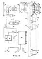
- FIG. 5 is a schematic view of the control system shown in Figure 3.
- the description of the preferred embodiment of the present invention shows a three door ballast gate with remote control positioning system embodying the present invention described in detail for use with railway hopper/ballast cars transporting and depositing road bed ballast. From the description, it will be easily understood that the present invention can be used for other types of railway cars, trailers and vehicles, hopper gate/door applications or any other advantageous applications for controlled discharge of a bulk substance.
- FIG. 1 there is shown a conventional hopper/ballast car 20 having a body 22 which is carried on a plurality of spaced apart trucks 24. Wheels 26 of the trucks 24, in turn, are positioned on a pair of rails 28.
- the car body 22 is defined by spaced sidewalls 30 which join end walls 32.
- the bottom of the car body 22 includes a platform 34 for mounting the car body 22 on the trucks 24.
- the end walls 32 and sidewalls 30 define the load-carrying space in the car body 22.
- the internal walls of the car body 22 are sloped downwardly so as to direct the ballast material to the generally rectangular-shaped discharge opening 36 formed by discharge walls 38 at the bottom of the car body, as shown in Figures 1 and 2.
- each car 20 includes four discharge openings 36, and each discharge opening 36 includes a ballast gate 40 with doors 42L, 42C, and 42R.
- the discharge openings 36 and attached ballast gates 40 are aligned down the longitudinal center line of the car 20 such that the aperture for each of the discharge openings 36 is generally positioned between the two rails 28 of the car 20.
- the ballast gate 40 is formed by two end plates 44, two top side plates 46, and two bottom discharge plates 48.
- the top side plates 46 extend longitudinally between the top corners of the end plates 44.
- the top side plates 46 have a flange 50 which is welded to the discharge walls 38 to help secure the ballast gate 40 to the discharge walls 38.
- the two bottom discharge plates 48 extend longitudinally between the bottom portion of the end plates 44. Each bottom discharge plate 48 is positioned in parallel, spaced-apart relationship with a corresponding top side plate 46 to form side apertures 52L, 52R for discharging ballast on the outside of rails 28.
- the bottom discharge plates 48 have a curved configuration and are spaced-apart from each other to form bottom aperture 52C.
- the doors 42L, 42R, 42C have the same general construction with door end plates 54 and curved plates 56.
- the narrow end of the door end plates 54 is pivotably connected to the end plate 44 at pivot point 58.
- the wide end of the door end plates 54 is used to secure the curved plates 56.
- the two side doors 42L, 42R have the door end plates 54 mounted on the outside of the end plates 44.
- the doors 42L, 42R are pivoted such that the curved plates 56 barely clear the outer edges of the end plates 44 and the top side plates 46.
- the curved plates 56 are made of plate steel or other heavy material such the gravitational force and hydraulic force are sufficient to close the curved plates of doors 42L, 42R against the bottom discharge plate 48.
- the center door 42C in order to pivot open and close, is mounted on the inside of the end plates 44.
- the hydraulic cylinder 60 is connected to and drives an external cam 62 which correspondingly rotates the center door 42C.
- the gaskets 64 are mounted on the edge of the bottom discharge plates 48 to ensure the proper seal about curved plate 56 of the center door 42C.
- the hydraulic cylinders 60 used to rotate the doors 42L, 42R, 42C have a fixed end 66 rotatably connected to the end plate 44 by brackets 68, 70.
- the piston rod 72 of the hydraulic cylinders 60 for the two side doors 42L, 42R are rotatably connected at bracket 74 to the door end plate 54 of a corresponding door such that the doors 42L, 42R can be selectively opened and closed to control the discharge of ballast.
- the extension and retraction of a piston rod 72 causes the corresponding door end plate 54 and curved plate 56 to rotate about pivot point 58.
- Each ballast gate 40 is provided with locking pins 75 which may be inserted into aligned holes 76 in the end plate 44 and door end plate 54 to selectively lock the doors 42L, 42R, 42C in a known manner.
- the doors can be locked in the closed position to prevent an unintentional discharge of ballast from occurring.
- Door safety stops adapted to limit the swing or pivoting of the doors 42L, 42R, 42C are affixed to the end wall 44.
- the hydraulic cylinders 60 are double-acting hydraulic motors of a type well known in the art shaving an inner port 78, an outer port 80, a piston 82 slidingly received in a cylinder 84, and a piston rod 72 suitably attached at one end to the piston 82.
- the other end of the piston rod 72 extends out of the outer end of the cylinder 84 and is secured to a mounting bracket 74 welded to the door end plate 54.
- each hopper car 20 has four ballast gates 40, with each ballast gate having three doors, a left door 42L, a right door 42R, and a center door 42C.
- the four center doors 42C are opened to direct ballast material between the rails 28.
- the left and right side doors 42L, 42R are opened to direct ballast material to the outside of the corresponding rail 28.
- the operator can selectively distribute ballast material to either side of the pair of rails 28 or between the rails 28 by opening the desired doors 42L, 42R, 42C on the ballast gates 40.
- the preferred method for positioning the doors 42 is a hydraulic system. However, electrical drive systems and pneumatic drive systems could also be used to open and close the doors 42 of the four ballast gates 40.
- Control systems and drive cylinders 60 or other motors are attached to the doors 42 on each of the hopper cars. The controls can be operated locally at a control station on each of the cars 20.
- the preferred system for controlling the ballast discharge is a remote control system 86 as shown in Figs. 3-5.
- the remote control system described herein is a radio frequency system with a pneumatic power source and hydraulic drives. However, infrared or other remote systems could be used to generate control signals in a similar manner. Instead of pneumatic power, electric power may be generated on a train and transmitted to the ballast cars for operating the ballast gates 40.
- the components of the control system 86 may be mounted on the platform 88 at either end of the hopper car 20. Pneumatic, electric, and hydraulic power may be transferred from car to car on the train in a conventional manner.
- the major components of a remote control system 86 are illustrated with a radio frequency remote operation and a pneumatic power supply.
- the pneumatic power supply 88 readily available on the hopper car 20 is converted to electrical power by the air motor 90 and alternator 92 to charge battery 94, which supplies power to controller-receiver 96.
- Pneumatic power is also delivered to the hydraulic pump 98, which converts the pneumatic power to hydraulic power to drive the hydraulic cylinders 60 used to position the doors 42L, 42C, 42R.
- the preferred embodiment of the positioning system 86 of the present invention is a twelve cylinder system using remote radio frequency control or other similar remote control system to independently operate the three door cylinders 60 on each of the ballast gates.
- the four ballast gates 40 have been numbered 1-4 and each of the three doors have been designated left "L”, right “R”, and center"C".
- the door positioning system 86 of the present invention is powered by a pneumatic power supply 88, which in the railroad hopper car application is a locomotive compressed air supply.
- a pneumatic power supply 88 which in the railroad hopper car application is a locomotive compressed air supply.
- Pneumatic power systems for trains, which supply and distribute compressed air from the locomotive to the other cars in the train, are known in the industry.
- the pneumatic power conduit 100 is connected to the pneumatic power supply 88 which extends from the locomotive in series to other cars in the train. Interposed in the pneumatic power conduit 100 is a normally open valve 102, which controls the entry of the compressed air into the positioning system 86. Valve 102 is maintained in the open position unless the operator desires to manually close the switch to disconnect the pneumatic power, such as to service the system 86.
- the filter-regulator-lubricator 104 in conduit 100 removes moisture and contaminants from the air, maintains the minimum pressure required in the system, and adds oil to lubricate the air operated components.
- Compressed air is then delivered through the conduit 106 to the air hydraulic pump 98 and through the conduit 108 to the air motor 90 for alternator 92.
- the regulated compressed air operates the hydraulic pump 98 to pump hydraulic fluid through conduit 110 to the solenoid hydraulic valve manifold 112.
- the manifold 112 includes a solenoid valve 114 for each door 42 to control the flow of hydraulic fluid to and from the hydraulic cylinders 60.
- the hydraulic pump 98 is provided with an integral air motor and pump.
- the hydraulic system typically includes a hydraulic reservoir 116 and hydraulic manifold 112.
- the hydraulic reservoir 116 stores the hydraulic fluid when the pump 98 is not in operation. Hydraulic pressure is supplied from the hydraulic pump 98 through the conduit 110 and the solenoid valves 90 in manifold 112 to cylinders 60.
- the hydraulic cylinders 60 are connected to doors 42 of the ballast gates 40.
- the hydraulic system includes pilot check valves 118 connected in series between the solenoid valves 90 and the cylinders 60.
- the check valve 118 is a differential pilot open check valve. When a pressure difference exists between port 78 and port 80, the valve is open. When the pressure is equal at both ports, the valve 118 is closed.
- the solenoid valve 114 is a spring centered, three position, four port valve.
- the center position 120 is a closed position, during which there is no hydraulic powered movement of the piston 82 or piston rod 72 in the cylinder 60.
- the conduit 110 is the power line delivering hydraulic power through the valve 114 to the cylinder 60.
- the center position 120 does have an open return line 122 which is connected to both port 78 and port 80. This equalizes the pressure at both ports 78, 80 when the valve 114 is in the center position 120 and permits any open doors 42L, 42C, 42R to return to the closed position if the hydraulic system loses power for any reason.
- valve 114 When the coil 124 of solenoid valve 114 is actuated to the right, the valve 114 shifts to the left or door opening position 126. In position 126, valve 114 causes hydraulic fluid to flow into port 80 and out of port 78 to move the piston 82 and extend the piston rod 72 until the coil 124 is de-actuated, at which time the spring return 130 causes valve 114 to return to the middle position 120.
- valve 114 When the coil 124 of solenoid valve 114 is actuated to the left, the valve 114 shifts to the right or door closing position 132. In position 132, valve 114 causes hydraulic fluid to flow into port 78 and out of port 80 to move the piston 82 in the opposite direction and retract the piston rod 72, which closes the door 42.
- a return line 122 returns the hydraulic fluid to a filter reservoir 116 which is connected to the air-operated hydraulic pump 98.
- conduit 108 is connected to an air motor 90 which drives an alternator 92.
- the air motor 90 is typically rated 1 horsepower or less with a 0.50 horsepower motor providing sufficient power in most cases.
- the air motor 90 may utilize a belt drive system or a direct coupling arrangement (not shown) to drive the alternator 92.
- Radio frequency controllers for remote operation require an electrical power supply, and will operate on either an alternating current (AC) or direct current (DC) system. Because of the remote location of the hopper cars and the unavailability of a conventional AC power supply, the battery powered DC power supply is the preferred power source.
- a 12 volt DC system similar to an automobile system, is utilized in the present invention.
- a standard 12 volt DC battery 94 provides an electrical source of power.
- Commercial generators and regulators are one means of providing power to charge the battery 94. It was discovered that an automobile type alternator 92 was a more space efficient and cost effective means of providing power to charge the battery 94.
- the alternator 92 is connected in parallel to battery 94.
- the alternator 92 charges the battery 94 until limited by the regulator (not shown) in the alternator 92 to prevent overload.
- the battery 94 provides the 12 volt DC power supply needed for operation of the controller 96 and for transmittal of the various control signals.
- the battery 94 is connected to controller 96 in series with a pressure switch 134.
- the controller 96 includes a receiver, decoder, timer and programmable control circuitry for receiving radio frequency signals, for decoding the radio frequency signals, for receiving other input signals (such as the pressure switch), and for transmitting control signals to control the operation of both the electrical system and the hydraulic drive system.
- the controller 96 will be described in more detail hereinafter.
- a signal means other than radio frequency can be used to for remote signalling purposes.
- the pressure switch 134 is interposed in the air supply conduit 108 to monitor the supply of compressed air being supplied to the electrical and hydraulic systems in the overall positioning system 86. When the desired compressed air supply is present, the pressure switch is closed electrically to connect the battery 94 and alternator 92 to the controller 96. When the compressed air supply is not present, the pressure switch 134 disconnects the controller 96 from the battery 94 and alternator 92. This prevents the undesirable drain on the battery and limits operation to when the alternator 92 is operable to charge the battery 94.
- the controller 96 is maintained in a stand by mode until a radio frequency signal is received for operational purposes. In the standby mode, a very low current drain occurs until a signal is received from the operator station 136, which is used for remote operation.
- the battery 94 is able to supply the necessary stand by power for an extended period of time without draining the battery 94.
- a solenoid actuated air valve 138 Interposed between the pressure switch 134 and the alternator 92 is a solenoid actuated air valve 138 which is controlled by the controller 96.
- the controller 96 transmits a signal to the solenoid air valve 138 to open the valve and permit the transmission of compressed air to operate the air motor 90 and alternator 92, which charges the battery 94.
- the operation of the air motor 90 and alternator 92 continues until the controller 96 transmits a signal to the air valve 138 to open the valve.
- the controller 96 includes a timing circuit to determine the period of time for which the air valve 138 is opened to operate the air motor 90 and alternator 92. Once the time period specified for operation has been completed, the air valve 138 closes and the controller 96 returns to the standby mode until the next radio frequency signal is received to operate the hydraulic cylinders 60. Every signal received by the controller 96 re-initializes the timing circuit and continues to operate the alternator 92 to charge the battery 94.
- the timing circuit reduces the operational wear on the air motor 90 and alternator 92, and reduces the overall pneumatic power consumption of the positioning system 86.
- the controller 96 shown in Fig 5 consists of a radio receiver and decoder, plus various control circuits and timing circuits for receiving input signals and decoded radio frequency transmissions and for transmitting signals to the hydraulic valves 114 which control the operation of the hydraulic cylinders 60.
- the control circuits may include a programmable controller to permit the operator to input performance variables for controller 96 operation, such as the timing or sequence of operation and an access-identification code for each individual hopper car 20.
- the radio receiver and decoder in the controller 96 is a standard model, such as Cattron model. Infrared and other remote transmitters and receivers could be used in place of radio frequency.
- the pressure switch 134 When the pressure switch 134 is open, the electrical power is disconnected and the controller 96 is not operable. When switch 134 is closed, power is supplied to the controller 96 and the controller 96 remains in a stand by mode until a operational signal is received from the operator station 136.
- the controller 96 includes an antenna 140 for receiving the radio frequency signals.
- the controller 96 When the remote radio frequency transmitter in the operator station 136 transmits a signal to the controller 96 through the antenna 140, or when a signal is received from the local push button control station 142, the controller 96 is changed into an operational mode. Control signals are transmitted from the controller 96 over output terminals SAV to open the solenoid air valve 138 to charge the battery 94, as discussed above, which ensures the availability that the necessary 12 volt DC power is available for operational purposes.
- the operator station 136 then transmits additional signals to instruct the controller 96 as to which cylinder 60 is to be actuated and in which direction the specified cylinder 60 is to be actuated.
- the controller 96 processes the signals received from the transmitter in operator staticn 136 and transmits control signals over the appropriate output terminals (S1-S12, one pair for each hydraulic cylinder) to the solenoid valve 114 of the specified cylinder 60.
- the operator station 136 is a battery powered unit and includes a standard radio frequency transmitter, such as the Cattron Model 824E-01.
- the operator station 136 also includes various battery powered control switches for generating signals to be transmitted by the transmitter to the receiver in controller 96.
- Fig. 4 shows three position, center-throw toggle switches 144 for operating the twelve gates, but other similar control switches would be acceptable for operation of the system.
- the car 20 To prepare the positioning system 86 for operation, the car 20 must be connected to the pneumatic power source 88.
- the pressure switch 134 is closed, which facilitates the connection of the battery 94 to the controller 96.
- the controller 96 is in the stand by mode.
- the compressed air operates the air motor-hydraulic pump 98 to build up the necessary pressure in the hydraulic system.
- each controller 96 includes an access circuit having an access identification number which may be set manually or programmed into the circuit.
- the identification number which is a digital code, must be received and processed by the controller 96 before any further positioning operations will occur.
- the operator When one or more cars 20 are in position on the tracks 28 for depositing ballast from car 20 through doors 42, the operator will use the operator station 136 to send a signal from a remote location to the controller 96 on the desired car 20.
- the operator station 136 must be activated using the on/off switch 146 to connect the battery (not shown) in station 136 to the transmitter and the control switches.
- the operator station 136 is then manually programmed to match the proper digital code to signal the desired car 20.
- the first selector switch 148 is rotated to set the first digit of the code
- the second selector switch 150 is rotated to set the second digit of the code
- the third selector switch 152 is rotated to set the third digit.
- the code "093" is shown as being selected.
- the next step requires the selection of one of the twelve doors on the four gate assemblies for operation.
- the operator station 136 is provided with twelve switches 144.
- the four gates 40 of the hopper car 20 have been designated gate 1, gate 2, gate 3, and gate 4 and the three doors on such gates as 1L, 1C, 1R, 2L etc.
- the toggle switch 144 designated for gate 1L is moved to the open position.
- a signal is generated and transmitted from the operator station 136 to the receiver in controller 96. Since the radio receiver/decoder 96 is now receiving its first signal, the controller 96 is placed in an operational mode.
- a signal is sent from the output terminals designated "SAV" to open the solenoid air valve 138 for the timed operation of the air motor 90 and alternator 92 to charge the battery 94.
- a control signal is transmitted from the appropriate output terminals (S1 for door 1L, S2 for door 1C, S3 for door 1R etc.) to the coil 124 of solenoid valve 114 to control operation of the solenoid 114 at the specified door.
- Each of the twelve hydraulic cylinder 60 has a corresponding solenoid operated valve 114 to individually control the operation of the cylinders 60.
- Identical valves 114 are used in the illustrated embodiment. However, it is noted that twelve separate sets of lines are shown leaving the controller 96 with only one pair of leads going to any one solenoid valve 114.
- the control signal will actuate the coil 124 of solenoid valve 114 of the appropriate cylinder 60 to solenoid position 126 to allow hydraulic fluid to enter outer port 80 and move the piston 82 and its associated piston rod 72 and cause the desired door 42 to open. Since the solenoid valve 114 is a spring return, the switch 144 must be held to the "open" position until the door 42 reaches the desired open position. When the door 42 reaches the desired position or the door 42 is in the fully opened position (hitting the door safety stops), the switch 144 is returned to its middle or neutral position and the solenoid valve 114, with springs 130, returns to the middle position 120.
- the switch 144 When it is desired to close the door 42, the switch 144 is moved to the "close" position which causes a signal to be transmitted from the operator station 136 through the controller 96 to the coil 124 of solenoid valve 114, which shifts the valve 114 to the position 132. Hydraulic fluid enters port 78, actuating the piston 82 and piston rod 72 to move the door 42 to the closed position.
- the operator station 136 may use a variety of switch arrangements. For example, the operator station 136 may control twelve cylinders by utilizing a four position selector switch to select one of the four gates 40, a three position selector switch to select left side door 42L, center door 42C, or right side door 42R of the gate 40, and a single center throw switch 144 to open and close the selected door.
- a local push button control station 142 electrically connected to the controller 96 and mounted on the car 20 could also be included to control the operation of the doors 42 to gate 40.
- the station 142 uses a similar switching system to selectively operate the cylinders 60 to position the doors 42.
Landscapes
- Engineering & Computer Science (AREA)
- Transportation (AREA)
- Mechanical Engineering (AREA)
- Power-Operated Mechanisms For Wings (AREA)
Applications Claiming Priority (2)
| Application Number | Priority Date | Filing Date | Title |
|---|---|---|---|
| US33495P | 1995-06-19 | 1995-06-19 | |
| US334 | 1995-06-19 |
Publications (1)
| Publication Number | Publication Date |
|---|---|
| EP0749879A1 true EP0749879A1 (de) | 1996-12-27 |
Family
ID=21691048
Family Applications (1)
| Application Number | Title | Priority Date | Filing Date |
|---|---|---|---|
| EP96401329A Withdrawn EP0749879A1 (de) | 1995-06-19 | 1996-06-19 | Trichterklappen für Eisenbahn-Schüttgutwagen und Positioniersystem |
Country Status (1)
| Country | Link |
|---|---|
| EP (1) | EP0749879A1 (de) |
Cited By (5)
| Publication number | Priority date | Publication date | Assignee | Title |
|---|---|---|---|---|
| CN101966902A (zh) * | 2010-10-19 | 2011-02-09 | 中国水利水电第七工程局有限公司 | 一种混凝土吊罐 |
| WO2018148094A1 (en) * | 2017-02-09 | 2018-08-16 | Trinity North American Freight Car, Inc. | Railcar with adjustable opening longitudinal gates |
| AU2015342461B2 (en) * | 2014-11-03 | 2018-12-06 | Crrc Yangtze Co., Ltd | Engineering vehicle having ballast unloading device and ballast levelling device |
| CN112277978A (zh) * | 2020-10-26 | 2021-01-29 | 中车眉山车辆有限公司 | 一种漏斗车用摆式卸货底门装置 |
| CN114162150A (zh) * | 2021-11-22 | 2022-03-11 | 中车株洲车辆有限公司 | 底门关闭状态监控装置及其方法 |
Citations (4)
| Publication number | Priority date | Publication date | Assignee | Title |
|---|---|---|---|---|
| FR426121A (fr) * | 1910-02-28 | 1911-06-28 | Leeds Forge Co Ltd | Perfectionnements aux wagons de chemin de fer et autres véhicules analogues |
| DE1161578B (de) * | 1958-10-25 | 1964-01-23 | Rheinstahl Siegener Eisenbahnb | Fernsteuerung zur Entleerung von im Zugverband fahrenden Schienenfahrzeugen |
| DE2115588A1 (de) * | 1970-11-30 | 1972-10-05 | Siemens Ag | Drahtgebundene Fernsteuerung für Betätigungsvorrichtungen, insbesondere Entladeklappen, eines aus mehreren Wagen zusammengesetzten Transportmittels mit beliebiger Reihenfolge der Wagen |
| US5359942A (en) * | 1993-08-27 | 1994-11-01 | Difco, Inc. | Remote control positioning system for controlling hopper doors |
-
1996
- 1996-06-19 EP EP96401329A patent/EP0749879A1/de not_active Withdrawn
Patent Citations (4)
| Publication number | Priority date | Publication date | Assignee | Title |
|---|---|---|---|---|
| FR426121A (fr) * | 1910-02-28 | 1911-06-28 | Leeds Forge Co Ltd | Perfectionnements aux wagons de chemin de fer et autres véhicules analogues |
| DE1161578B (de) * | 1958-10-25 | 1964-01-23 | Rheinstahl Siegener Eisenbahnb | Fernsteuerung zur Entleerung von im Zugverband fahrenden Schienenfahrzeugen |
| DE2115588A1 (de) * | 1970-11-30 | 1972-10-05 | Siemens Ag | Drahtgebundene Fernsteuerung für Betätigungsvorrichtungen, insbesondere Entladeklappen, eines aus mehreren Wagen zusammengesetzten Transportmittels mit beliebiger Reihenfolge der Wagen |
| US5359942A (en) * | 1993-08-27 | 1994-11-01 | Difco, Inc. | Remote control positioning system for controlling hopper doors |
Cited By (8)
| Publication number | Priority date | Publication date | Assignee | Title |
|---|---|---|---|---|
| CN101966902A (zh) * | 2010-10-19 | 2011-02-09 | 中国水利水电第七工程局有限公司 | 一种混凝土吊罐 |
| CN101966902B (zh) * | 2010-10-19 | 2011-12-21 | 中国水利水电第七工程局有限公司 | 一种混凝土吊罐 |
| AU2015342461B2 (en) * | 2014-11-03 | 2018-12-06 | Crrc Yangtze Co., Ltd | Engineering vehicle having ballast unloading device and ballast levelling device |
| WO2018148094A1 (en) * | 2017-02-09 | 2018-08-16 | Trinity North American Freight Car, Inc. | Railcar with adjustable opening longitudinal gates |
| US10449975B2 (en) | 2017-02-09 | 2019-10-22 | Trinity North American Freight Car, Inc. | Railcar with adjustable opening longitudinal gates |
| US11273851B2 (en) | 2017-02-09 | 2022-03-15 | Trinity North American Freight Car, Inc. | Railcar with adjustable opening longitudinal gates |
| CN112277978A (zh) * | 2020-10-26 | 2021-01-29 | 中车眉山车辆有限公司 | 一种漏斗车用摆式卸货底门装置 |
| CN114162150A (zh) * | 2021-11-22 | 2022-03-11 | 中车株洲车辆有限公司 | 底门关闭状态监控装置及其方法 |
Similar Documents
| Publication | Publication Date | Title |
|---|---|---|
| US5359942A (en) | Remote control positioning system for controlling hopper doors | |
| US6431084B1 (en) | Railroad hopper car gate assembly and method of operating same | |
| US6067912A (en) | Automated discharge system for hopper car | |
| US9156479B2 (en) | Hydraulic switch machine for railroads | |
| CN114044033B (zh) | 基于列车类型信息自动调控列车闭塞制式的系统及方法 | |
| US7980636B2 (en) | Automated gate control and methods | |
| US20140360401A1 (en) | System and Method for Powered Railcar Doors | |
| US20110006592A1 (en) | System and Method for Accumulation of Air for Pneumatic Railroad Car Systems | |
| EP0749879A1 (de) | Trichterklappen für Eisenbahn-Schüttgutwagen und Positioniersystem | |
| US3316857A (en) | Motor actuated closure mechanism for railway hopper cars | |
| US3417883A (en) | Transfer station for handling refuse | |
| US5029532A (en) | Control cab | |
| US3446373A (en) | Remotely controlled automatic hopper car door actuating mechanism | |
| US4944564A (en) | Brake valve device arranged for electro-pneumatic control | |
| US3433373A (en) | Automatic vehicle door control system | |
| USRE48026E1 (en) | Hydraulic switch machine for railroads | |
| US3374908A (en) | System for loading train of cars with solid fluent material | |
| KR101863491B1 (ko) | 출입문 선택 제어 회로 | |
| US3251487A (en) | System for loading train of cars with solid fluent material | |
| SU1250604A1 (ru) | Машина цикличного действи дл путевых работ | |
| JPH07172316A (ja) | 空電併用連結器の自動解結装置 | |
| US1639717A (en) | averill | |
| CN108749832B (zh) | 铁路漏斗车开闭控制系统及控制方法 | |
| RU213402U1 (ru) | Кран машиниста железнодорожного транспортного средства | |
| RU216872U1 (ru) | Блок тормозного оборудования |
Legal Events
| Date | Code | Title | Description |
|---|---|---|---|
| PUAI | Public reference made under article 153(3) epc to a published international application that has entered the european phase |
Free format text: ORIGINAL CODE: 0009012 |
|
| AK | Designated contracting states |
Kind code of ref document: A1 Designated state(s): AT BE CH DE DK ES FI FR GB GR IE IT LI LU MC NL PT SE |
|
| 17P | Request for examination filed |
Effective date: 19970310 |
|
| 17Q | First examination report despatched |
Effective date: 19981211 |
|
| STAA | Information on the status of an ep patent application or granted ep patent |
Free format text: STATUS: THE APPLICATION IS DEEMED TO BE WITHDRAWN |
|
| 18D | Application deemed to be withdrawn |
Effective date: 19990622 |