EP0749929A2 - Méthodes et appareil pour le bobinage de filaments - Google Patents
Méthodes et appareil pour le bobinage de filaments Download PDFInfo
- Publication number
- EP0749929A2 EP0749929A2 EP96201868A EP96201868A EP0749929A2 EP 0749929 A2 EP0749929 A2 EP 0749929A2 EP 96201868 A EP96201868 A EP 96201868A EP 96201868 A EP96201868 A EP 96201868A EP 0749929 A2 EP0749929 A2 EP 0749929A2
- Authority
- EP
- European Patent Office
- Prior art keywords
- package
- thread
- winding
- contact roller
- contact
- Prior art date
- Legal status (The legal status is an assumption and is not a legal conclusion. Google has not performed a legal analysis and makes no representation as to the accuracy of the status listed.)
- Granted
Links
Images


Classifications
-
- B—PERFORMING OPERATIONS; TRANSPORTING
- B65—CONVEYING; PACKING; STORING; HANDLING THIN OR FILAMENTARY MATERIAL
- B65H—HANDLING THIN OR FILAMENTARY MATERIAL, e.g. SHEETS, WEBS, CABLES
- B65H59/00—Adjusting or controlling tension in filamentary material, e.g. for preventing snarling; Applications of tension indicators
- B65H59/38—Adjusting or controlling tension in filamentary material, e.g. for preventing snarling; Applications of tension indicators by regulating speed of driving mechanism of unwinding, paying-out, forwarding, winding, or depositing devices, e.g. automatically in response to variations in tension
- B65H59/384—Adjusting or controlling tension in filamentary material, e.g. for preventing snarling; Applications of tension indicators by regulating speed of driving mechanism of unwinding, paying-out, forwarding, winding, or depositing devices, e.g. automatically in response to variations in tension using electronic means
- B65H59/385—Regulating winding speed
-
- B—PERFORMING OPERATIONS; TRANSPORTING
- B65—CONVEYING; PACKING; STORING; HANDLING THIN OR FILAMENTARY MATERIAL
- B65H—HANDLING THIN OR FILAMENTARY MATERIAL, e.g. SHEETS, WEBS, CABLES
- B65H54/00—Winding, coiling, or depositing filamentary material
- B65H54/02—Winding and traversing material on to reels, bobbins, tubes, or like package cores or formers
- B65H54/28—Traversing devices; Package-shaping arrangements
- B65H54/2884—Microprocessor-controlled traversing devices in so far the control is not special to one of the traversing devices of groups B65H54/2803 - B65H54/325 or group B65H54/38
-
- B—PERFORMING OPERATIONS; TRANSPORTING
- B65—CONVEYING; PACKING; STORING; HANDLING THIN OR FILAMENTARY MATERIAL
- B65H—HANDLING THIN OR FILAMENTARY MATERIAL, e.g. SHEETS, WEBS, CABLES
- B65H54/00—Winding, coiling, or depositing filamentary material
- B65H54/02—Winding and traversing material on to reels, bobbins, tubes, or like package cores or formers
- B65H54/40—Arrangements for rotating packages
- B65H54/52—Drive contact pressure control, e.g. pressing arrangements
-
- B—PERFORMING OPERATIONS; TRANSPORTING
- B65—CONVEYING; PACKING; STORING; HANDLING THIN OR FILAMENTARY MATERIAL
- B65H—HANDLING THIN OR FILAMENTARY MATERIAL, e.g. SHEETS, WEBS, CABLES
- B65H63/00—Warning or safety devices, e.g. automatic fault detectors, stop-motions ; Quality control of the package
- B65H63/006—Warning or safety devices, e.g. automatic fault detectors, stop-motions ; Quality control of the package quality control of the package
-
- B—PERFORMING OPERATIONS; TRANSPORTING
- B65—CONVEYING; PACKING; STORING; HANDLING THIN OR FILAMENTARY MATERIAL
- B65H—HANDLING THIN OR FILAMENTARY MATERIAL, e.g. SHEETS, WEBS, CABLES
- B65H2511/00—Dimensions; Position; Numbers; Identification; Occurrences
- B65H2511/10—Size; Dimensions
- B65H2511/16—Irregularities, e.g. protuberances
-
- B—PERFORMING OPERATIONS; TRANSPORTING
- B65—CONVEYING; PACKING; STORING; HANDLING THIN OR FILAMENTARY MATERIAL
- B65H—HANDLING THIN OR FILAMENTARY MATERIAL, e.g. SHEETS, WEBS, CABLES
- B65H2513/00—Dynamic entities; Timing aspects
- B65H2513/10—Speed
-
- B—PERFORMING OPERATIONS; TRANSPORTING
- B65—CONVEYING; PACKING; STORING; HANDLING THIN OR FILAMENTARY MATERIAL
- B65H—HANDLING THIN OR FILAMENTARY MATERIAL, e.g. SHEETS, WEBS, CABLES
- B65H2515/00—Physical entities not provided for in groups B65H2511/00 or B65H2513/00
- B65H2515/30—Forces; Stresses
- B65H2515/32—Torque e.g. braking torque
-
- B—PERFORMING OPERATIONS; TRANSPORTING
- B65—CONVEYING; PACKING; STORING; HANDLING THIN OR FILAMENTARY MATERIAL
- B65H—HANDLING THIN OR FILAMENTARY MATERIAL, e.g. SHEETS, WEBS, CABLES
- B65H2515/00—Physical entities not provided for in groups B65H2511/00 or B65H2513/00
- B65H2515/30—Forces; Stresses
- B65H2515/34—Pressure, e.g. fluid pressure
-
- B—PERFORMING OPERATIONS; TRANSPORTING
- B65—CONVEYING; PACKING; STORING; HANDLING THIN OR FILAMENTARY MATERIAL
- B65H—HANDLING THIN OR FILAMENTARY MATERIAL, e.g. SHEETS, WEBS, CABLES
- B65H2701/00—Handled material; Storage means
- B65H2701/30—Handled filamentary material
- B65H2701/31—Textiles threads or artificial strands of filaments
Definitions
- the present invention relates to developments in the filament winding system disclosed in U.S. 4,548,366 (EP 182 389).
- U.S. Patent No. 4,548,366 discloses a winding arrangement in which a contact roller (in contact with the outer surface of a filament package) is driven to apply a controlled force to the package surface while the speed of rotation of the roller is regulated by regulating the speed of rotation of the package.
- U.S. Patent No. 4,765,552 (corresponding to European Publication 0 254 944) discloses limitation of the controlled force to a range given by a motor torque for the contact roller between 0 and 1.5 Newton-centimeter per filament package. This latter specification is unclear in its explanation of the quoted range but the justification appears to relate either to avoidance of "small slips" which cause yarn quality variations or to avoidance of speed differentials giving tube damage at first contact of the roller with a bare bobbin tube.
- German Document 35 13 796 proposes a drive system in which the package is driven on its circumference by a friction drive roll while thread from a traverse motion is laid on the package by an additional contact roll.
- the contact roll is driven to give a slight excess speed of the contact roll relative to the package. This is designated to enable control of thread tension.
- U.S. Patent 4,986,483 describes in some detail the problems discussed below (in the section "Problem Addressed") and proposes a combination of a drive system of the type discussed above with a special traverse cam device.
- the drive system is intended to be operated in a manner such as to avoid the transmission of circumferential force between the contact roller and the package for minimizing the generation of slip between the contact roller and the package.
- German Document 41 26 392 describes a system to apply feedback control to the generation of the motor torque for the contact roller.
- the generated motor torque is related directly to the circumferential force transferred between the roller and the package.
- German Document 41 26 392 The stated purpose of the arrangement according to German Document 41 26 392 is the achievement of control over the force transmitted at the interface between the roller and the package. By this means, slip at the interface is to be avoided. According to the German specification, slip is especially likely to occur when contact pressure is low and the system is subject to variations which risk an approach to or exceeding of the slip limit. Another stated purpose is to avoid occurrence of inhomogeneities over the period of winding a package.
- the present invention addresses the problem of building a cylindrical cross-wound package of filament under conditions such that the threadline tension immediately upstream from the winder is at a level which, if the same threadline tension persisted through to the package, would cause package build problems before the desired package dimensions are achieved.
- package build problems as related to thread tension, will be given.
- the contact roller has long been used as a device for mitigating the first effect.
- the contact pressure applied by this roller it is possible to flatten the shoulders to some extent.
- the flattening effect is limited by outward bulging of package ends (i.e., the package side walls) due to the applied pressure (see Fig. 13). Therefore, as previously indicated, sooner or later (as package diameter increases) shoulders will appear and when they reach a certain size they lead to unstable thread layers within the package and hence to problems in subsequent unwinding for further processing.
- the second effect works together with the threadline tension to exaggerate the first effect. Because package density is lower in the central region, the package is more easily compressible in its central region than at its ends. The tension of the thread as it is wound into the package exerts a compressing effect on the underlying thread layers (and on the tube which forms the core of the package). The greater the thread tension, therefore, the greater the compressing effect and the more the central package region is squeezed in relative to the end regions.
- the present invention is based upon a realisation that it is possible to monitor packages produced in a winder and to improve sub-optimal package build by adapting at least one winding parameter.
- the thread winding machine is provided with a control device adapted to adjust predetermined winding parameters in dependence upon an evaluation of a package produced by the machine in a winding operation.
- the machine may additionally comprise an evaluation means for evaluating a package produced during a winding operation and for providing a corresponding signal or group of signals to the control means.
- Packages from a group of winders could be provided to a common evaluation station from which the evaluation signal or signals are transmitted to the respective winders. In this case, however, it is necessary to arrange for coordination of the products of the individual winding machines with the signals produced in the evaluation station so that the latter signals can be returned to the appropriate winders.
- each winding machine is provided with its own evaluation means which is preferably adapted to respond to the condition of a completed package.
- the evaluation means can be provided, e.g. in the region of the doffing or stand-by position to respond to the package condition as soon as full packages arrive in that position. The resulting signals can be supplied to the machine control to adapt winding parameters before the next winding operation is started.
- the evaluation means is preferably adapted to evaluate package condition on the basis of package build (package structure). In particular, it is possible to evaluate on the one hand saddle formation and on the other hand building of the axial end walls of the package.
- An evaluation means for this purpose can be based upon known optical image analysis techniques.
- the present invention enables larger diameter packages to be built by reducing the rate of formation of the saddle shape (Fig. 12) and/or axial bulging (Fig. 13) on the package.
- This is achieved by building test packages, inspecting their shape for deviations from a cylindrical shape, and then changing the thread tension at laydown in the package in order to reduce the rate of formation of such deviation in a subsequent test package.
- slippage at the interface between a contact roller and the package is promoted, and the amount of slippage is changed between the forming of respective test packages in order to vary the thread tension at laydown in the package.
- the amount of slippage can be changed by changing the pressing force generating the contact pressure between the contact roller and package and/or changing the circumferential force transmitted between the contact roller and package.
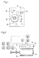
- the machine shown diagrammatically in Figs. 1 and 2 is a high-speed winder for thread of synthetic plastics filament.
- the machine is described with reference to a single threadline only. However, the machine may be adapted to handle a plurality of threadlines simultaneously.
- the elements shown in Figs. 1 and 2 are illustrated in the conditions they adopt during a thread winding operation because the present invention is particularly concerned with the machine in that condition. Other machine conditions will be referred to only briefly in the course of this description.
- the example chosen to illustrate the invention has a single chuck.
- the invention is equally applicable to automatic winding machines having more than one chuck, e.g. a pair of chucks which can be brought alternately into a winding position.
- this type of machine will be described with reference to Fig. 9 but since the invention itself is concerned primarily with an individual winding operation it can be explained adequately by reference to the single chuck machine shown in Figs. 1 and 2.
- the machine comprises a frame and housing structure ("frame") 10 on which the other parts are mounted.
- a chuck 12 is mounted to extend cantilever-fashion from the front face of the frame 10. This chuck 12 is rotatable about its longitudinal axis 16 by means of an asynchronous electric motor 18 (Fig. 2).
- Chuck 12 is movable by means (not shown) towards and away from a contact roll 20 which is mounted in the frame 10 for rotation about its roll axis 22 (Fig. 2). Rotation of roll 22 about this axis 22 is produced by an asynchronous electric motor 24 which is designed with an external rotor enclosing a stator fixed to the frame.
- Movement of chuck 12 towards and away from roll 20 involves movement of axis 16 along a curved path 26 (Fig. 1). At one end of the path 26, furthest spaced from the roll 20, chuck 12 has a rest position in which a package 30 formed during a winding operation can be removed from the chuck and replaced by an empty tube 28 upon which a new package can be built in the next winding operation.
- the chuck At the other end of the path 26, closest to contact roll 20, the chuck enters a winding position in which a thread 32 delivered to the winder can be wound on the tube 28 to form the package 30.
- the winding machine is of the well-known "print friction" type in which a thread 32 passes around a portion of the circumference of the contact roll 20 before being transferred from that roll to the package 30.
- the thread is reciprocated longitudinally of the chuck axis 16 by means of a conventional traverse mechanism 36 provided upstream (considered in the direction of movement of the thread) from the contact roll 20.
- a control means for controlling the winding speed is shown in Fig. 2, in the condition it adopts when contact has been established between the contact roll 20 and the package 30 so that driving force can be transmitted between the contact roll and the package.
- This control system comprises a tacho generator 42 coupled to the rotor or drive shaft of the contact roll 20, a tacho generator 44 coupled to the drive shaft of the chuck 12, an invertqr 46 for feeding the roll motor 24, an invertor 48 for feeding the chuck motor 18, a regulator 50 for regulating the output of the invertor 46, a regulator 52 for regulating the output of the invertor 48, a setting device 54 operable to set the output of the invertor 46, a setting device 56 for providing a setting value to the regulator 52, an auxiliary setting device 58 and a timer 60.
- regulator 52 is receiving the output of its setting device 56 and also the output of the tacho-generator 42. Regulator 52 compares the inputs from the setting device 56 and generator 42 and provides an output to the invertor 48 in dependence upon this comparison. Inverter 48 supplies a corresponding input to the motor 18 to control the speed of the latter.
- tacho-generator 44, device 58 and timer 60 play no direct part in the control operation.
- These elements are provided primarily for use during a package changeover when contact has to be made between a new tube 28 and/or package 30 and contact roll 20. Suitable arrangements for this purpose are described in U.S. Patent No. 4,548,366, but those arrangements are not essential to the present invention and they will not be described herein.
- Contact roll 20 is influenced on one hand by reason of its contact with the package 30 and on the other hand by reason of its connection with motor 24.
- motor 24 receives an input from its own invertor 46.
- This input is determined directly by the setting device 54 which for this purpose is connected directly to the invertor 46.
- the effect of variation in the setting of device 54 has been disclosed broadly in U.S. Patent 4,548,366 (especially in the description of Fig. 6 thereof) and this effect will be discussed further below after additional explanation of the goals to be intended to be achieved by means of the present invention.
- the present invention concentrates instead upon the conditions needed to ensure a good package build. That is, the winding conditions which lead to a good package structure.
- the indirect effects upon yarn quality will be achieved insofar as yarn defects generated by package structural faults are eliminated by means of the present invention.
- U.S. Patent 4,548,366 describes a method of influencing the circumferential force generated at the interface between a contact roller and a package in a system as illustrated in Figs. 1 and 2.
- the subsequent introduction of "yarn quality" as a central goal for the operation of such a system has led to misjudgment of the role of slip in the contact region between the roller and the package.
- U.S. Patent 4,548,366 assumes the absence of slippage in this contact region. This assumption was made for the purpose of explanation of the operation of the contact roller as a measuring device for the circumferential (tangential) speed of the package surface. The assumption is not raised in U.S. Patent 4,548,366 to the status of an essential feature of the system and subsequent investigations have shown that it is in fact impossible to avoid generation of slip in the contact region if the goal of adjustable (i.e. variable) setting of circumferential force is to be achieved. This conclusion is consistent with theoretical studies of motion transmission systems involving transmission of drive by means of rolling surfaces, see e.g. the textbook "milletti" by G. Niemenn and H. Winter, Springer Verlag; Volume 3, Pages 182 to 201.
- the present invention is directed primarily to the goal of influencing thread tension downstream from the contact roller (i.e. in the newly forming outermost layer of the thread package) relative to the threadline tension upstream from the contact roller.
- the latter tension which is beyond the control of this invention, is determined by the technology of the filament spinning process and by the design of the installation upstream from the winder. It is technically feasible but economically highly undesirable to tailor the winder design specifically to a given spinning process. In practical terms, therefore, a filament winder must be designed to build an acceptable package from filaments exhibiting an infeed tension (i.e. threadline tension at the entry into the winder) variable within a significant range (e.g. from 0.1 to 0.3 gm/dtex), while an ideal package build is usually obtained only with thread tension at the laydown point in the range 0.08 to 0.15 gm/dtex.
- the desired adjustment in thread tension is effected by generating circumferential force in the contact region between the contact roller and the package such as to create a controlled difference in velocity of the surface of the roller relative to the surface of the package.
- this invention seeks to influence thread tension at the package circumference relative to thread tension in the threadline upstream from the roller by generating controlled slippage at the interface between the contact roller and the surface layer of the package. This contrasts with the prior art in which attempts have been made to eliminate such slippage, or in which the slippage has been assumed to be absent.
- the yarn can be caused to relax as it is transferred from the roller to the package.
- This relaxation will correspond with a reduction in the elastic elongation of the yarn in the surface layer of the package relative to the corresponding elongation of the yarn on the surface of the contact roller. This is the mode of operation most generally applicable in modern processing techniques which inherently tend towards relatively high threadline tensions at the entrance to the filament winder.
- this invention is not limited to the roller advance system providing relaxation of yarn tension for winding.
- threadline tension at the entrance to the winder is too low to enable successful package build. This is especially true in spinning of filament at low speed (for example below 1000 m/min.).
- Such processes are used for spinning yarn which is subsequently passed to a separate drawing stage (for example a drawtwister).
- a separate drawing stage for example a drawtwister.
- Some industrial yarns and tire cords are processed in this way.
- Low speed processes are also used for production of high modulus filaments, for example so-called aramids.
- An increase in tension between the infeed to the winder and the point of laydown in the package can also be advantageous in high speed spinning of relatively thick filaments.
- the present invention is used to ensure a higher circumferential speed of the package relative to the circumferential speed of the contact roller ("package advance") so that the yarn is actually additionally stretched as it is transferred from the roller to the outer package layer. That is, the elastic elongation of the yarn in the surface layer of the package is higher than the corresponding elongation of the yarn on the surface of the contact roller.
- the level of slippage generated at the roller/package interface is controlled, i.e. is maintained within an acceptably narrow range of values (tolerance range) throughout the winding operation.
- the contact roller in accordance with this invention still represents an essential element of the measuring means by which the circumferential speed of the package itself is to be controlled. Accordingly, if unpredictable levels of slippage were to arise at the interface region, the feedback signal generated by means of the contact roller would have no significance for the package and it would then be impossible to maintain controlled winding conditions giving uniform and reproducible yarn characteristics. However, for the purposes of a given winding operation, it is not necessary to know the level of slippage which will be generated.
- the circumferential speed of the contact roller is in any event held at a predetermined level by means of the feed back loop described generally with reference to Figs. 1 and 2 and in further detail in U.S. Patent No. 4,548,366.
- the system can then be operated in preliminary tests under the given winding conditions to determine the setting for the contact roller drive giving optimum package build under the given winding and spinning conditions, including filament type and titer, spin finish, winding contact pressure, etc.
- the system is fully specified by the set value for the circumferential speed of the contact roller and the setting for the drive motor of that roller without precise knowledge of the slippage level.
- the relevant characteristic for evaluating the performance of the system is not in any event the slippage level generated at the roller/package interface but the package build which can be achieved by exploitation of a speed differential at that interface.
- the surface of the contact roller acts as an element in the arrangement for transmitting the traverse motion to the roller/package interface.
- the surface of the contact roller acts as a member in the arrangement for ensuring that the motion of a "yarn element" (i.e. a very short length of yarn) at the moment at which it is laid on the package surface is substantially determined by the motion imparted to that "yarn element” at the instant at which it was in direct co-operation with the traverse device. If slippage were to arise between the yarn and the surface of the contact roller upstream from the roller/package interface, then control would be lost over the thread tension at the point of the laying of the thread onto the package surface.
- the angle of wrap of the element EE on the member RM is indicated by the angle W.
- the coefficient of friction between the element EE and the member RM is indicated by the symbol F.
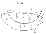
- FIG. 3 The classical analysis according to Fig. 3 corresponds in the case of a filament winder arranged according to the assumed operating condition illustrated in the schematic perspective view shown in Fig. 4 in which parts corresponding to the parts shown in Fig. 1 are indicated again by the some reference numerals.
- Reference numeral 70 indicates the thread guide of the traverse motion 36 (Fig. 1). This guide is assumed to be moving in the direction of the arrow 72 towards the right-hand end of contact roller 20 as viewed in Fig. 4.
- the line 74 on the surface of roller 20 represents the locus of points at which the thread 32 first contacts the roller 20 as the thread is swept backwards and forwards along the length of that roller by the traverse motion imparted to thread guide 70.
- the dotted line 76 indicates the corresponding locus of points at which the thread is laid onto the outermost surface of the package 30 giving a laydown pattern on the package surface in the form generally indicated at 78.
- This laydown pattern includes reversal regions 80, 82 at respective edges of the package joined by straight intermediate sections 84.
- An angle C is enclosed between each intermediate section 84 and an imaginary line L drawn on the surface of the package and extending parallel to the axis of rotation thereof.
- This angle C is called the helix angle and is equal to half the so-called cross winding angle which represents an important winding parameter exerting a significant influence upon package structure.
- the angle C is determined by the speed of traverse of the guide 70 relative to the speed at which thread 32 is delivered to the winder.
- the angle of wrap W of the thread on the contact roller 20 is indicated as approximately 90° and is defined by the two radii joining the lines 74, 76 to the axis 16 of the roller 20 in a plane which also contains the point of contact of the thread with the thread guide 70. That is, in the simplified approach, it is assumed that there is no inclination of the thread in the axial direction of the roller 20 between the thread guide 70 and the currently effective point of laydown of the thread on the surface of the package 30. As previously indicated, under such circumstances the mathematical analysis derived for systems as illustrated in Fig. 3 is equally applicable to a system as illustrated in Fig. 4. However, the schematical illustration in Fig. 4 represents a simplification relative to a practical winding operation the circumstances of which are closer to those illustrated schematically in Fig. 5.
- the drag length encloses the cross winding angle between itself and the tangent TG to the surface of the contact roller 20 at the first contact point FC. Accordingly, the length of the yarn lying in contact with the surface of roller 20 between the point of first contact FC and the point at which the yarn is being transferred to the surface of the package 30 is no longer assumed to lie in the normal plane previously referred to but to follow a helical path SP around the surface of the roller.
- the previously indicated mathematical relationship between thread tension upstream from the roller 20 and thread tension in the surface layer of the package 30 should therefore be modified to include a term representing the influence of the cross winding angle.
- the cross winding angle can be increased by reducing the traverse speed of the thread traversing device.
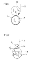
- the layer of thread forming on the outer surface of bobbin tube 28 is therefore invisible in this Figure. There is practically direct contact between the outer surface of tube 28 (which is supported on its interior by the chuck 12) and the outer surface of roller 20. The material of tube 28 can be assumed to be practically incompressible under these circumstances, and there is virtually line contact at the laydown region IR.
- Fig. 7 the same package is illustrated ata later stage of the winding operation but some time before package diameter d (Fig. 7) has reached the maximum dimension intended.
- the outer layers of package 30 in Fig. 7 are soft relative to the bobbin tube 28 (Fig. 6) and accordingly the contact roll is now pressed into the package somewhat in the contact region giving an indentation in the interface region.
- the degree of indentation arising in an individual winding operation depends upon the contact pressure generated at the roller/package interface and the hardness (density) of the package.
- the presence of this indentation implies that slippage between the surface of the roller and the surface of the package is unavoidable in the region of contact of those surfaces.
- Fig. 7A which represents schematically the interface region of Fig. 7 to a larger scale.
- the indented surface of the package undergoes a gradual reduction in circumferential speed between the points Q and P, and a corresponding increase in circumferential speed between the points P and R. It is, therefore, impossible to match the surface speed of the roller with the surface speed of the package at all points within the region of indentation.
- the calculated speed difference at point P in tests made at delivery speeds (contact roller speeds) between 3500 m/min and 4000 m/min indicate a speed difference at the point P in the range 0.5% to 1.5% under the test conditions (pressing force 60 N) for the zero setting and the roller advance mode.
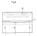
- each wall region of the package has the maximum package diameter D, but the central region of the package has a reduced diameter D1 so that the interface region I is now formed only between contact roller 20 and the axially spaced wall regions.
- the degree of pulling in of the central package region relative to the wall regions has been exaggerated for purposes of illustration in Fig. 8, but the maximum diameter package for given winding conditions will exhibit a small degree of central tightening of this kind. It is in fact the appearance of an unacceptable level of pulling in of the central package region relative to the wall regions which characterizes or defines the maximum possible package diameter. It is the aim of the present invention to enable adaptation of other winding conditions to enable this limit condition to be reached without intermediate thread breakage or breaking off of the winding operation for other reasons.
- the effect of the slippage generated between the roller and the package should be reduced from the beginning to the end of the winding operation to allow for the degree of relaxation of the thread in the central region of the package associated with the effects illustrated schematically (and in an exaggerated form) in Fig. 8.
- the effect of the controlled slippage in the interface region is designed to increase thread tension on the surface of the package relative to threadline tension upstream from the winder then this effect should be increased from the beginning to the end of the winding operation to allow for the relaxation in the central region which will arise as explained with reference to Fig. 8.
- the conditions in the interface region between the contact roller 20 and the package 30 are determined not only by the relative velocities of the mutually contacting surfaces. Those conditions are determined also by the contact pressure exerted between the contact roller 20 and the chuck 12.
- the fact that contact pressure can exert a significant influence upon level of slippage generated under conditions of rolling contact has been demonstrated by the studies of rolling drive systems previously referred to.
- the adaptation of the interface conditions to a given winding operation therefore involves the appropriate control of both the mutual velocities of the contacting surfaces and the contact pressure generated between them.
- Devices for generating contact pressure in filament winders have been known for a considerable length of time and will not be described in detail in this specification. For the sake of completeness, however, an automatic winding machine of the type particularly intended to be operated in accordance with this invention will now be briefly described with reference to Fig. 9. The generation of contact pressure will be briefly indicated in the context of the description of Fig. 9.
- Fig. 9 shows a frame 10, a contact roller 20, a traverse device 36, and a thread 32 to be wound.
- the winder shown in Fig. 9 is, however, of the automatic type comprising a revolver 90 carrying a pair of cantilever-mounted chucks 12, 14, each of which carries bobbin tubes 28 in use. In the condition illustrated in Fig. 9, winding has started on the tube(s) of the chuck 12, those tubes being in contact with the contact roller 20.
- the chuck 14 has recently been moved out of the winding position into a lowermost "stand-by" or doffing position in which full packages 30 on the chuck 14 have been (can be) removed from the chuck. This should happen as soon as possible after the changeover operation has been completed, in order to allow for rapid build-up of a new package forming on the chuck 12 now in the winding position.
- roller 20 and traverse device 36 are carried by a cantilever-mounted carriage 94 which is vertically movable along guides 96.
- piston and cylinder units 98 are controllably operated from a programmable control unit 100 located behind an operating panel 102 in the upper left portion of the machine as illustrated in Fig. 9, which may comprise a model RIEMAT A6-09 winder sold by Rieter Chemical Fiber Systems.
- the angle of wrap W of the filament on the contact roller 20 illustrated in Fig. 9 is approximately 90°. This is determined by the geometry of the winder design and cannot be significantly adapted without a major modification in that geometry.
- the coefficient of friction between the filament and the surface of the roller is radically affected by the spinning conditions (e.g. the cross section of the filament involved, the application of lubricants and possibly other fluids to the threadline upstream from the winder, and to some extent by the surface condition of the contact roller itself).
- winding tension can be at the most increased by a factor of 1.7 relative to the threadline tension or at the most decreased by a factor of 1.7 relative to the threadline tension.
- winding tension can be controllably determined by choosing the setting of the drive to the contact roller while maintaining a given winding speed determined by the set value for comparison with the feedback signal from the contact roller.
- the circumferential force applied by the contact roller to the package increases and thereby produces an increase in slip between the contact roller and package to reduce the thread tension at laydown in the package relative to thread tension at the winder inlet.
- the thread tension at laydown in the package would be increased relative to thread tension at the winder inlet.
- the motor generating an output torque which is applied directly to the contact roller 20 is an asynchronous motor 24 supplied by invertor 46.
- the characteristic linking output torque and rotor speed for a motor for this type is illustrated in Fig. 10 in which motor torque in Newton-meters is represented on the vertical axis and motor revolutions on the horizontal axis.
- the dotted line box represents the limits of the physical capabilities of the motor, in particular the maximum torque which can be generated by a motor of this type under load.
- Fig. 10 can be interpreted as follows:
- the output torque generated at the surface of the contact roller can be taken as a direct measure of the circumferential force supplied by the contact roller 20 to the package in contact therewith because the diameter of the contact roller is fixed (in contrast to the diameter of the package which varies throughout the winding operation). This circumferential force is distributed across the axial length of the package surface (or across the total axial length of all packages contacting the roller 20 in the event that a plurality of packages are formed simultaneously on a single chuck in contact with the roller 20).
- the filament newly laid onto the surface of a package occupies only a small part of the total surface of contact established between the roller 20 and the package 13.
- the thread does not "respond" to the total circumferential force exerted by the contact rail, but only to the local effect of that force at the laydown point. Accordingly, it is not the total circumferential force (effective motor torque) applied to a package, that is significant, but rather the circumferential force generated per unit length of contact between the roller and the package.
- a chuck of length 900 mm can carry eight packages of axial length 85 mm or two packages of axial length 410 mm.
- the tension effect achieved by applying an effective torque of 1.2 Nm to the eight packages will be approximately the same as the tension effect achieved by applying an effective torque of approximately 1 Nm (i.e., 0.5 Nm per package) to the two packages (for a given filament and with otherwise unchanged winding conditions).
- the effect of a given frequency setting for the contact roll will therefore vary slightly over the period of a winding operation because of the gradual change in effective "contact length" between a given package and the contact roller for the reasons explained with reference Fig. 8. This represents a further reason for modifying the tension adjusting settings in a pre-programmed manner throughout the period of a given winding operation.
- a first test package of a given thread is wound in the usual manner, with the rotary speed of the contact roller 20 being kept constant to produce a constant draw tension on the thread approaching the interface between the contact roller and the package.
- the winding is stopped and the package is inspected for its surface appearance to determine whether, during the winding of the next test package, the apparatus should be operated in the "package advance” mode or "roller advance” mode, as described earlier herein. If humps have formed on the package surface, it is likely that the thread tension at the package inlet was too low, dictating that during the next winding operation, the apparatus would be operated in the "package advance” mode.
- the tension at laydown is increased relative to thread tension at the inlet to the winder.
- the setting of the contact roll is thereby adjusted so that the package transfers drive force to the roller (acting in a braking mode) either until the humps disappear or until the limit of the permissible tension adjustment (see the discussion of Figs. 3 to 5) is reached. In the latter case, the thread cannot be wound under the given conditions and some adjustments must be made upstream from the winder.
- the possible settings for the contact roller drive are adjustable over a range such that the maximum possible tension adjustment (as determined by slip on the contact roller) is achievable by adjusting the drive roller setting alone, i.e., without additionally altering further winding parameters such as the contact pressure.
- the contact pressure itself can then be set independently in the light of other winding conditions, as will appear from the following discussion of faults which can be treated by means other than an increase in tension between the winder inlet and the laydown point.
- the following description refers to winding of a series of packages, with evaluation of each package in the series enabling adjustment of winding parameters before winding of the next package in the series.
- the "package” referred to in each case may be one of a "group” of packages formed simultaneously (in one winding operation, on a single chuck).
- the results derived from the "package” referred to in the following description stand for the results of a given winding operation in a series of such operations.
- the operator visually inspects the package to determine whether there are any other deviations therein from a cylindrical shape, for example a saddle shape (Fig. 12) or side wall bulging (Fig. 13). It is known according to the prior art, to deal with such deviations by changing the cross winding angle and/or the contact pressure.
- the present invention adds another adjustment feature which can be exploited together with the previously known possibilities to deal with the problems found under the given winding conditions.
- Changes in cross winding angle and contact pressure may in any event have to be associated with offsetting changes in the setting of the contact roll drive in order to give optimum package build. This is relatively easily appreciated in relation to contact pressure, which affects directly the friction and therefore the degree of slip appearing at the interface for a given level of circumferential force generated by the contact roll motor.
- contact pressure has to be increased (in an attempt to "squash" the walls of a saddle formation)
- this will increase the friction force at the interface and decrease the slip level at the interface for a given setting of a contact roll motor.
- This will decrease the thread tension effect previously obtained at the given setting.
- a subsequent increase in the contact roll drive setting may therefore give a better result than that obtainable by retaining the setting used before the change in contact pressure.
- a "pattern" is established for each winding parameter (or at least, for the variable winding parameter).
- the parameter in question is then varied in accordance with this predetermined pattern from the start to the end of the winding operation.
- Each of the three previously mentioned winding parameters can be varied in this way according to a preset pattern, that is the cross winding angle, the contact pressure and the winding tension (relative to the tension at the winder inlet).
- the pattern could involve a continuous change in the parameter as winding proceeds.
- the pattern involves a stepwise change in the pattern as is already used (for example) in the winding of so-called step precision wound packages.
- the pattern is preferably defined as a function of package diameter, because this parameter is commonly measured in the currently available winders. This is not, however, essential.
- the pattern could be defined, for example, as a function of time since the time required to wind a given package will be either calculable or readily determinable empirically.
- the thread winding machine is provided with a control device adapted to adjust predetermined winding parameters in dependence upon an evaluation of a package produced by the machine in a winding operation.
- the machine may additionally comprise an evaluation means for evaluating a package produced during a winding operation and for providing a corresponding signal or group of signals to the the control means.
- each winding machine is provided with its own evaluation means which is preferably adapted to respond to the condition of a completed package.
- evaluation means which is preferably adapted to respond to the condition of a completed package.
- the evaluation means is preferably adapted to evaluate package condition on the basis of package build (package structure).
- package build package structure
- An evaluation means for this purpose can be based upon known optical image analysis techniques.
- Fig. 12 shows a perspective view of a winder essentially similar to that shown in Fig. 9, the same reference numerals being used to indicate the same parts.
- the winder in Fig. 11 includes a frame 10, a vertically reciprocable carriage 94 and a pair of chucks 12, 14 mounted on a revolver.
- the latter has not been illustrated in Fig. 11, because it is not essential to the features now to be described and will in any event be readily apparent from the illustration in Fig. 9 itself.
- the winder shown in Fig. 11 is additionally provided with an elongated hollow carrier element 104 extending from the frame 10 parallel to a chuck (in Fig. 11, the chuck 14) in the doffing position.
- Carrier 104 carries four package structure evaluating devices 106 corresponding respectively with the four packages produced in this case during each winding operation.
- Each evaluating device 106 is connected by leads (not shown) extending along the interior of the carrier element 104 into the frame 10 for connection to the control unit 100 (Fig. 9).
- Each evaluating means 106 is adapted to evaluate two criteria of package build or package structure as illustrated in Figs. 12 and 13, respectively.
- Each of Figs. 12 and 13 illustrates in full lines a "perfect" package 30 of a predetermined maximum diameter D and axial length L.
- D maximum diameter
- L axial length
- the effective axial length of the package at an intermediate point between the carrier tube 28 and the outer cylindrical surface of the package will be greater by an amount ⁇ L than the predetermined length L.
- Figs. 12 and 13 The package defects illustrated in Figs. 12 and 13 are essentially determined by three winding parameters, namely:
- the cross winding angle can be controlled, for example, by controlling the speed of axial traverse of the thread guide 70 (Figs. 4 and 5) for a given delivery speed of the thread 32.
- the thread tension at the point of lay-down in the package can be controlled by the contact pressure, and the setting of the drive to the contact roller, described with reference to Figs. 1 to 10.
- the control unit 100 is programmed with control functions, e.g. in the form:
- the control unit 100 can be adapted to store the actual values of ⁇ D and ⁇ L obtained from a series of winding operations and to analyze such series of values for tendencies (or the absence of such tendencies).
- the winder can then be made self-regulating (self-optimizing) so that the three winding parameters are adjusted to minimize, as far as possible, the values of ⁇ D and ⁇ L obtained for further winding operations.
- the machine would preferably be designed to change the settings of winding parameters between the winding of the first and second test packages, if the evaluation of the first package indicates package building problems. Thereafter, the machine would automatically inspect and evaluate a series of winding operations to detect trends in the deviation formation, the changing of winding parameters being performed manually.
Landscapes
- Engineering & Computer Science (AREA)
- Quality & Reliability (AREA)
- Microelectronics & Electronic Packaging (AREA)
- Winding Filamentary Materials (AREA)
- Filamentary Materials, Packages, And Safety Devices Therefor (AREA)
Applications Claiming Priority (3)
| Application Number | Priority Date | Filing Date | Title |
|---|---|---|---|
| US151888 | 1993-11-15 | ||
| US08/151,888 US5533686A (en) | 1993-11-15 | 1993-11-15 | Methods and apparatus for the winding of filaments |
| EP94117412A EP0655409B1 (fr) | 1993-11-15 | 1994-11-04 | Méthode pour le bobinage de filaments |
Related Parent Applications (2)
| Application Number | Title | Priority Date | Filing Date |
|---|---|---|---|
| EP94117412A Division EP0655409B1 (fr) | 1993-11-15 | 1994-11-04 | Méthode pour le bobinage de filaments |
| EP94117412.0 Division | 1994-11-04 |
Publications (3)
| Publication Number | Publication Date |
|---|---|
| EP0749929A2 true EP0749929A2 (fr) | 1996-12-27 |
| EP0749929A3 EP0749929A3 (fr) | 1997-02-12 |
| EP0749929B1 EP0749929B1 (fr) | 1999-08-18 |
Family
ID=22540669
Family Applications (2)
| Application Number | Title | Priority Date | Filing Date |
|---|---|---|---|
| EP96201868A Expired - Lifetime EP0749929B1 (fr) | 1993-11-15 | 1994-11-04 | Méthodes et appareil pour le bobinage de filaments |
| EP94117412A Expired - Lifetime EP0655409B1 (fr) | 1993-11-15 | 1994-11-04 | Méthode pour le bobinage de filaments |
Family Applications After (1)
| Application Number | Title | Priority Date | Filing Date |
|---|---|---|---|
| EP94117412A Expired - Lifetime EP0655409B1 (fr) | 1993-11-15 | 1994-11-04 | Méthode pour le bobinage de filaments |
Country Status (5)
| Country | Link |
|---|---|
| US (2) | US5533686A (fr) |
| EP (2) | EP0749929B1 (fr) |
| JP (1) | JP3637356B2 (fr) |
| CN (2) | CN1113208A (fr) |
| DE (2) | DE69420152T2 (fr) |
Cited By (3)
| Publication number | Priority date | Publication date | Assignee | Title |
|---|---|---|---|---|
| EP0812794A3 (fr) * | 1996-06-11 | 1999-01-07 | Murata Kikai Kabushiki Kaisha | Dispositif pour l'inspection de la qualité de bobines |
| EP0861800A3 (fr) * | 1997-02-26 | 1999-05-06 | Murata Kikai Kabushiki Kaisha | Dispositif de contrÔle pour un bobinoir |
| WO2006024356A1 (fr) * | 2004-08-30 | 2006-03-09 | Saurer Gmbh & Co. Kg | Procede et dispositif pour optimaliser les parametres de travail d'un poste de travail d'une machine textile produisant des bobines croisees |
Families Citing this family (17)
| Publication number | Priority date | Publication date | Assignee | Title |
|---|---|---|---|---|
| US5533686A (en) * | 1993-11-15 | 1996-07-09 | Maschinenfabrik Rieter Ag | Methods and apparatus for the winding of filaments |
| CH691856A5 (de) * | 1997-02-18 | 2001-11-15 | Rieter Ag Maschf | Spulendorn. |
| DE19802509A1 (de) * | 1998-01-23 | 1999-07-29 | Rieter Ag Maschf | Aufwindevorrichtung für Endlosfäden |
| DE102004007757A1 (de) * | 2004-02-18 | 2005-09-08 | Saurer Gmbh & Co. Kg | Antriebswalze für eine Kreuzspulen herstellende Textilmaschine |
| JP4582721B2 (ja) * | 2004-02-27 | 2010-11-17 | ザウラー ゲゼルシャフト ミット ベシュレンクテル ハフツング ウント コンパニー コマンディートゲゼルシャフト | 複数の糸を巻取るための方法及び装置 |
| KR101121405B1 (ko) * | 2004-03-03 | 2012-03-15 | 엘리콘 텍스타일 게엠베하 운트 코. 카게 | 다수의 실을 감기 위한 장치 및 방법 |
| KR20050123449A (ko) * | 2004-06-25 | 2005-12-29 | 최영호 | 섬유사 권취장치 |
| CN101618809B (zh) * | 2009-07-20 | 2012-02-22 | 南京航空航天大学 | 低损伤控制放纱装置及方法 |
| MX339655B (es) * | 2010-04-07 | 2016-06-02 | Dsm Ip Assets B V * | Ovillo con hilo de módulo elástico longitudinal alto y método para bobinar el ovillo de hilo. |
| CN104150260A (zh) * | 2014-07-28 | 2014-11-19 | 四川石棉华瑞电子有限公司 | 铝箔运行张力检测装置、铝箔运行张力调整装置及方法 |
| US10526124B2 (en) * | 2016-05-25 | 2020-01-07 | International Business Machines Corporation | Surface distortion detector for packaging |
| DE102016215953A1 (de) * | 2016-08-25 | 2018-03-15 | Volkswagen Aktiengesellschaft | Wickelverfahren und Wickelvorrichtung zum kontinuierlichen Bewickeln eines Kernes |
| US10746640B2 (en) * | 2017-03-21 | 2020-08-18 | Textron Innovations Inc. | Methods of making a tubular specimen with a predetermined wrinkle defect |
| US10744727B2 (en) | 2017-03-21 | 2020-08-18 | Textron Innovations Inc. | Methods of making a specimen with a predetermined wrinkle defect |
| CN110804776B (zh) * | 2019-11-13 | 2021-06-18 | 杭州诚天旺丝绸有限公司 | 一种改进型纺织罗拉 |
| JP7384763B2 (ja) * | 2020-08-04 | 2023-11-21 | トヨタ自動車株式会社 | 繊維束巻取装置 |
| CN115123880A (zh) * | 2021-01-18 | 2022-09-30 | 裴达江 | 一种电线卷取装置用防护机构的使用方法 |
Family Cites Families (22)
| Publication number | Priority date | Publication date | Assignee | Title |
|---|---|---|---|---|
| US3288383A (en) * | 1964-06-17 | 1966-11-29 | Karlsruhe Augsburg Iweka | Automatic control arrangement for spooling drives |
| DE1248218B (de) * | 1964-03-03 | 1967-08-24 | Barmag Barmer Maschf | Aufwickelvorrichtung zur Bildung fester Spulenkoerper |
| DE2200627A1 (de) * | 1971-01-26 | 1973-01-25 | Spinnereimaschb Karl Marx Stad | Vorrichtung zum konstanthalten der aufwickelgeschwindigkeit, insbesondere an aufwickelmaschinen fuer synthetische faeden |
| JPS5232035B2 (fr) * | 1972-07-17 | 1977-08-18 | ||
| US3991950A (en) * | 1973-02-09 | 1976-11-16 | Kabushiki Kaisha Toyoda Jidoshokki Seisakusho | Method and apparatus for making yarn packages of cheese form by a textile machine |
| DE2513981A1 (de) * | 1975-03-29 | 1976-10-07 | Schlafhorst & Co W | Verfahren und vorrichtung zum steuern und/oder regeln der fadenspannung beim wickeln einer textilspule |
| CH618401A5 (fr) * | 1975-06-12 | 1980-07-31 | Barmag Barmer Maschf | |
| CH605272A5 (fr) * | 1975-08-08 | 1978-09-29 | Barmag Barmer Maschf | |
| DE2721972C3 (de) * | 1977-05-14 | 1979-12-06 | Barmag Barmer Maschinenfabrik Ag, 5630 Remscheid | Aufspulvorrichtung für Fäden |
| US4548366A (en) * | 1982-05-17 | 1985-10-22 | Rieter Machine Works, Ltd. | Chuck drive system |
| US4677387A (en) * | 1984-01-12 | 1987-06-30 | Rieter Machine Works, Ltd. | Package quality monitor |
| DE3513796A1 (de) * | 1984-04-21 | 1985-12-05 | Barmag Barmer Maschinenfabrik Ag, 5630 Remscheid | Aufspulvorrichtung |
| JPS6262937A (ja) * | 1985-09-10 | 1987-03-19 | Murata Mach Ltd | 巻糸パツケ−ジの巻形検査装置 |
| DE3750193T2 (de) * | 1986-04-09 | 1994-12-01 | Asahi Chemical Ind | Spulmaschine für synthetische Fäden, Kreuzspule aus synthetischen Fäden und Verfahren zum Wickeln solcher Spulen. |
| US4877967A (en) * | 1986-06-03 | 1989-10-31 | Murata Kikai Kabushiki Kaisha | Package inspecting apparatus |
| JPS6327378A (ja) * | 1986-07-16 | 1988-02-05 | Teijin Seiki Co Ltd | 巻取機の駆動方法 |
| DE3810365A1 (de) * | 1988-03-26 | 1989-10-05 | Schlafhorst & Co W | Verfahren und vorrichtung zum ermitteln des spulenumfangs von kreuzspulen und zum verwerten des ergebnisses |
| EP0367726B1 (fr) * | 1988-11-04 | 1993-01-07 | Maschinenfabrik Rieter Ag | Dispositif de compensation de l'affaissement de la broche de bobinage dans une machine à bobiner |
| EP0371912A1 (fr) * | 1988-11-28 | 1990-06-06 | Maschinenfabrik Rieter Ag | Dispositif pour la commande de pression |
| US5315366A (en) * | 1991-04-09 | 1994-05-24 | Murata Kikai Kabushiki Kaisha | Yarn package inspecting apparatus |
| DE59205648D1 (de) * | 1991-07-04 | 1996-04-18 | Rieter Ag Maschf | Verfahren zur Übergabe des Fadens von einer vollen Spule an eine leere Hülse und eine Spulmaschine |
| US5533686A (en) * | 1993-11-15 | 1996-07-09 | Maschinenfabrik Rieter Ag | Methods and apparatus for the winding of filaments |
-
1993
- 1993-11-15 US US08/151,888 patent/US5533686A/en not_active Expired - Fee Related
-
1994
- 1994-11-04 EP EP96201868A patent/EP0749929B1/fr not_active Expired - Lifetime
- 1994-11-04 DE DE69420152T patent/DE69420152T2/de not_active Expired - Fee Related
- 1994-11-04 DE DE69405197T patent/DE69405197T2/de not_active Expired - Fee Related
- 1994-11-04 EP EP94117412A patent/EP0655409B1/fr not_active Expired - Lifetime
- 1994-11-10 JP JP30014394A patent/JP3637356B2/ja not_active Expired - Fee Related
- 1994-11-14 CN CN94117912A patent/CN1113208A/zh active Pending
-
1996
- 1996-05-23 US US08/653,699 patent/US5797551A/en not_active Expired - Fee Related
-
2000
- 2000-04-10 CN CN00106572A patent/CN1269321A/zh active Pending
Cited By (3)
| Publication number | Priority date | Publication date | Assignee | Title |
|---|---|---|---|---|
| EP0812794A3 (fr) * | 1996-06-11 | 1999-01-07 | Murata Kikai Kabushiki Kaisha | Dispositif pour l'inspection de la qualité de bobines |
| EP0861800A3 (fr) * | 1997-02-26 | 1999-05-06 | Murata Kikai Kabushiki Kaisha | Dispositif de contrÔle pour un bobinoir |
| WO2006024356A1 (fr) * | 2004-08-30 | 2006-03-09 | Saurer Gmbh & Co. Kg | Procede et dispositif pour optimaliser les parametres de travail d'un poste de travail d'une machine textile produisant des bobines croisees |
Also Published As
| Publication number | Publication date |
|---|---|
| EP0655409B1 (fr) | 1997-08-27 |
| US5797551A (en) | 1998-08-25 |
| DE69420152T2 (de) | 1999-12-16 |
| DE69420152D1 (de) | 1999-09-23 |
| CN1113208A (zh) | 1995-12-13 |
| DE69405197D1 (de) | 1997-10-02 |
| DE69405197T2 (de) | 1998-01-02 |
| CN1269321A (zh) | 2000-10-11 |
| EP0749929B1 (fr) | 1999-08-18 |
| JP3637356B2 (ja) | 2005-04-13 |
| EP0655409A2 (fr) | 1995-05-31 |
| US5533686A (en) | 1996-07-09 |
| EP0655409A3 (fr) | 1995-09-06 |
| EP0749929A3 (fr) | 1997-02-12 |
| JPH07215586A (ja) | 1995-08-15 |
Similar Documents
| Publication | Publication Date | Title |
|---|---|---|
| EP0749929B1 (fr) | Méthodes et appareil pour le bobinage de filaments | |
| US6145775A (en) | Yarn winding apparatus and method | |
| EP2075359B1 (fr) | Dispositif d'élimination du relâchement des fils et machine de filature | |
| US4548366A (en) | Chuck drive system | |
| JP2617305B2 (ja) | 糸繰返し方法及び装置 | |
| US5343601A (en) | Yarn spinning method with high-speed winding | |
| US5957402A (en) | Method and apparatus for reducing catenary during winding of a fiber bundle | |
| JP3509756B2 (ja) | 糸条加工装置 | |
| EP2112258A2 (fr) | Dispositif et procédé d'enroulement d'une mèche sur une bobine | |
| US4308716A (en) | Apparatus for applying liquid to a running yarn | |
| EP1630268B1 (fr) | Procédé permettant d'assurer la qualité d'un fil textile et machine de traitement de fil | |
| US6523774B2 (en) | Method and apparatus for winding a continuously advancing yarn | |
| US4789112A (en) | Yarn winding method and resulting package | |
| CN100462489C (zh) | 断线预防装置和具有断线预防单元的纱线处理机器 | |
| US4471917A (en) | Balloon-control guide and yarn rewinding process | |
| KR20000069721A (ko) | 연속 주행사를 권취하기 위한 방법 및 장치 | |
| US6402080B1 (en) | Arrangement and method for winding threads onto bobbins with random crosswinding | |
| US4274604A (en) | Winding machine | |
| JP2000026021A (ja) | 綾巻きボビンを作製する繊維機械の作動方法 | |
| US4917319A (en) | Method of winding yarn packages | |
| US3358433A (en) | Collection of synthetic polymeric yarns or filaments | |
| US4112662A (en) | Winding machines | |
| JP3003274B2 (ja) | 粗紡機の運転方法 | |
| WO2001023257A2 (fr) | Procede et appareil servant a enrouler un fil sur une bobine | |
| JP3533786B2 (ja) | 糸条の巻取方法および巻取装置 |
Legal Events
| Date | Code | Title | Description |
|---|---|---|---|
| PUAI | Public reference made under article 153(3) epc to a published international application that has entered the european phase |
Free format text: ORIGINAL CODE: 0009012 |
|
| PUAL | Search report despatched |
Free format text: ORIGINAL CODE: 0009013 |
|
| AC | Divisional application: reference to earlier application |
Ref document number: 655409 Country of ref document: EP |
|
| AK | Designated contracting states |
Kind code of ref document: A2 Designated state(s): CH DE ES FR GB IT LI |
|
| AK | Designated contracting states |
Kind code of ref document: A3 Designated state(s): CH DE ES FR GB IT LI |
|
| 17P | Request for examination filed |
Effective date: 19970613 |
|
| 17Q | First examination report despatched |
Effective date: 19970717 |
|
| GRAG | Despatch of communication of intention to grant |
Free format text: ORIGINAL CODE: EPIDOS AGRA |
|
| GRAG | Despatch of communication of intention to grant |
Free format text: ORIGINAL CODE: EPIDOS AGRA |
|
| GRAH | Despatch of communication of intention to grant a patent |
Free format text: ORIGINAL CODE: EPIDOS IGRA |
|
| GRAH | Despatch of communication of intention to grant a patent |
Free format text: ORIGINAL CODE: EPIDOS IGRA |
|
| GRAA | (expected) grant |
Free format text: ORIGINAL CODE: 0009210 |
|
| AC | Divisional application: reference to earlier application |
Ref document number: 655409 Country of ref document: EP |
|
| AK | Designated contracting states |
Kind code of ref document: B1 Designated state(s): CH DE ES FR GB IT LI |
|
| REG | Reference to a national code |
Ref country code: CH Ref legal event code: EP |
|
| REF | Corresponds to: |
Ref document number: 69420152 Country of ref document: DE Date of ref document: 19990923 |
|
| PGFP | Annual fee paid to national office [announced via postgrant information from national office to epo] |
Ref country code: GB Payment date: 19991022 Year of fee payment: 6 |
|
| PGFP | Annual fee paid to national office [announced via postgrant information from national office to epo] |
Ref country code: CH Payment date: 19991025 Year of fee payment: 6 |
|
| PGFP | Annual fee paid to national office [announced via postgrant information from national office to epo] |
Ref country code: FR Payment date: 19991026 Year of fee payment: 6 |
|
| ITF | It: translation for a ep patent filed | ||
| PGFP | Annual fee paid to national office [announced via postgrant information from national office to epo] |
Ref country code: ES Payment date: 19991117 Year of fee payment: 6 |
|
| ET | Fr: translation filed | ||
| REG | Reference to a national code |
Ref country code: CH Ref legal event code: AEN Free format text: DAS PATENT IST AUFGRUND DES WEITERBEHANDLUNGSANTRAGS VOM 29.11.1999 REAKTIVIERT WORDEN. |
|
| REG | Reference to a national code |
Ref country code: ES Ref legal event code: FG2A Ref document number: 2138287 Country of ref document: ES Kind code of ref document: T3 |
|
| PLBE | No opposition filed within time limit |
Free format text: ORIGINAL CODE: 0009261 |
|
| STAA | Information on the status of an ep patent application or granted ep patent |
Free format text: STATUS: NO OPPOSITION FILED WITHIN TIME LIMIT |
|
| 26N | No opposition filed | ||
| PG25 | Lapsed in a contracting state [announced via postgrant information from national office to epo] |
Ref country code: GB Free format text: LAPSE BECAUSE OF NON-PAYMENT OF DUE FEES Effective date: 20001104 |
|
| PG25 | Lapsed in a contracting state [announced via postgrant information from national office to epo] |
Ref country code: ES Free format text: LAPSE BECAUSE OF NON-PAYMENT OF DUE FEES Effective date: 20001105 |
|
| PG25 | Lapsed in a contracting state [announced via postgrant information from national office to epo] |
Ref country code: LI Free format text: LAPSE BECAUSE OF FAILURE TO SUBMIT A TRANSLATION OF THE DESCRIPTION OR TO PAY THE FEE WITHIN THE PRESCRIBED TIME-LIMIT Effective date: 20001130 Ref country code: CH Free format text: LAPSE BECAUSE OF FAILURE TO SUBMIT A TRANSLATION OF THE DESCRIPTION OR TO PAY THE FEE WITHIN THE PRESCRIBED TIME-LIMIT Effective date: 20001130 |
|
| GBPC | Gb: european patent ceased through non-payment of renewal fee |
Effective date: 20001104 |
|
| REG | Reference to a national code |
Ref country code: CH Ref legal event code: PL |
|
| PG25 | Lapsed in a contracting state [announced via postgrant information from national office to epo] |
Ref country code: FR Free format text: LAPSE BECAUSE OF NON-PAYMENT OF DUE FEES Effective date: 20010731 |
|
| REG | Reference to a national code |
Ref country code: FR Ref legal event code: ST |
|
| REG | Reference to a national code |
Ref country code: ES Ref legal event code: FD2A Effective date: 20011214 |
|
| PG25 | Lapsed in a contracting state [announced via postgrant information from national office to epo] |
Ref country code: IT Free format text: LAPSE BECAUSE OF NON-PAYMENT OF DUE FEES Effective date: 20051104 |
|
| PGFP | Annual fee paid to national office [announced via postgrant information from national office to epo] |
Ref country code: DE Payment date: 20061124 Year of fee payment: 13 |
|
| PG25 | Lapsed in a contracting state [announced via postgrant information from national office to epo] |
Ref country code: DE Free format text: LAPSE BECAUSE OF NON-PAYMENT OF DUE FEES Effective date: 20080603 |