EP0750137A2 - Méthode de projet d'un variateur hydromécanique continu de vitesse à division de puissance - Google Patents
Méthode de projet d'un variateur hydromécanique continu de vitesse à division de puissance Download PDFInfo
- Publication number
- EP0750137A2 EP0750137A2 EP96109646A EP96109646A EP0750137A2 EP 0750137 A2 EP0750137 A2 EP 0750137A2 EP 96109646 A EP96109646 A EP 96109646A EP 96109646 A EP96109646 A EP 96109646A EP 0750137 A2 EP0750137 A2 EP 0750137A2
- Authority
- EP
- European Patent Office
- Prior art keywords
- planetary gear
- power
- transmission
- gear
- coupled
- Prior art date
- Legal status (The legal status is an assumption and is not a legal conclusion. Google has not performed a legal analysis and makes no representation as to the accuracy of the status listed.)
- Withdrawn
Links
Images





Classifications
-
- F—MECHANICAL ENGINEERING; LIGHTING; HEATING; WEAPONS; BLASTING
- F16—ENGINEERING ELEMENTS AND UNITS; GENERAL MEASURES FOR PRODUCING AND MAINTAINING EFFECTIVE FUNCTIONING OF MACHINES OR INSTALLATIONS; THERMAL INSULATION IN GENERAL
- F16H—GEARING
- F16H47/00—Combinations of mechanical gearing with fluid clutches or fluid gearing
- F16H47/02—Combinations of mechanical gearing with fluid clutches or fluid gearing the fluid gearing being of the volumetric type
- F16H47/04—Combinations of mechanical gearing with fluid clutches or fluid gearing the fluid gearing being of the volumetric type the mechanical gearing being of the type with members having orbital motion
-
- F—MECHANICAL ENGINEERING; LIGHTING; HEATING; WEAPONS; BLASTING
- F16—ENGINEERING ELEMENTS AND UNITS; GENERAL MEASURES FOR PRODUCING AND MAINTAINING EFFECTIVE FUNCTIONING OF MACHINES OR INSTALLATIONS; THERMAL INSULATION IN GENERAL
- F16H—GEARING
- F16H37/00—Combinations of mechanical gearings, not provided for in groups F16H1/00 - F16H35/00
- F16H37/02—Combinations of mechanical gearings, not provided for in groups F16H1/00 - F16H35/00 comprising essentially only toothed or friction gearings
- F16H37/06—Combinations of mechanical gearings, not provided for in groups F16H1/00 - F16H35/00 comprising essentially only toothed or friction gearings with a plurality of driving or driven shafts; with arrangements for dividing torque between two or more intermediate shafts
- F16H37/08—Combinations of mechanical gearings, not provided for in groups F16H1/00 - F16H35/00 comprising essentially only toothed or friction gearings with a plurality of driving or driven shafts; with arrangements for dividing torque between two or more intermediate shafts with differential gearing
- F16H37/0833—Combinations of mechanical gearings, not provided for in groups F16H1/00 - F16H35/00 comprising essentially only toothed or friction gearings with a plurality of driving or driven shafts; with arrangements for dividing torque between two or more intermediate shafts with differential gearing with arrangements for dividing torque between two or more intermediate shafts, i.e. with two or more internal power paths
- F16H37/084—Combinations of mechanical gearings, not provided for in groups F16H1/00 - F16H35/00 comprising essentially only toothed or friction gearings with a plurality of driving or driven shafts; with arrangements for dividing torque between two or more intermediate shafts with differential gearing with arrangements for dividing torque between two or more intermediate shafts, i.e. with two or more internal power paths at least one power path being a continuously variable transmission, i.e. CVT
-
- F—MECHANICAL ENGINEERING; LIGHTING; HEATING; WEAPONS; BLASTING
- F16—ENGINEERING ELEMENTS AND UNITS; GENERAL MEASURES FOR PRODUCING AND MAINTAINING EFFECTIVE FUNCTIONING OF MACHINES OR INSTALLATIONS; THERMAL INSULATION IN GENERAL
- F16H—GEARING
- F16H37/00—Combinations of mechanical gearings, not provided for in groups F16H1/00 - F16H35/00
- F16H37/02—Combinations of mechanical gearings, not provided for in groups F16H1/00 - F16H35/00 comprising essentially only toothed or friction gearings
- F16H37/06—Combinations of mechanical gearings, not provided for in groups F16H1/00 - F16H35/00 comprising essentially only toothed or friction gearings with a plurality of driving or driven shafts; with arrangements for dividing torque between two or more intermediate shafts
- F16H37/08—Combinations of mechanical gearings, not provided for in groups F16H1/00 - F16H35/00 comprising essentially only toothed or friction gearings with a plurality of driving or driven shafts; with arrangements for dividing torque between two or more intermediate shafts with differential gearing
- F16H37/0833—Combinations of mechanical gearings, not provided for in groups F16H1/00 - F16H35/00 comprising essentially only toothed or friction gearings with a plurality of driving or driven shafts; with arrangements for dividing torque between two or more intermediate shafts with differential gearing with arrangements for dividing torque between two or more intermediate shafts, i.e. with two or more internal power paths
- F16H37/084—Combinations of mechanical gearings, not provided for in groups F16H1/00 - F16H35/00 comprising essentially only toothed or friction gearings with a plurality of driving or driven shafts; with arrangements for dividing torque between two or more intermediate shafts with differential gearing with arrangements for dividing torque between two or more intermediate shafts, i.e. with two or more internal power paths at least one power path being a continuously variable transmission, i.e. CVT
- F16H2037/0866—Power-split transmissions with distributing differentials, with the output of the CVT connected or connectable to the output shaft
-
- F—MECHANICAL ENGINEERING; LIGHTING; HEATING; WEAPONS; BLASTING
- F16—ENGINEERING ELEMENTS AND UNITS; GENERAL MEASURES FOR PRODUCING AND MAINTAINING EFFECTIVE FUNCTIONING OF MACHINES OR INSTALLATIONS; THERMAL INSULATION IN GENERAL
- F16H—GEARING
- F16H37/00—Combinations of mechanical gearings, not provided for in groups F16H1/00 - F16H35/00
- F16H37/02—Combinations of mechanical gearings, not provided for in groups F16H1/00 - F16H35/00 comprising essentially only toothed or friction gearings
- F16H37/06—Combinations of mechanical gearings, not provided for in groups F16H1/00 - F16H35/00 comprising essentially only toothed or friction gearings with a plurality of driving or driven shafts; with arrangements for dividing torque between two or more intermediate shafts
- F16H37/08—Combinations of mechanical gearings, not provided for in groups F16H1/00 - F16H35/00 comprising essentially only toothed or friction gearings with a plurality of driving or driven shafts; with arrangements for dividing torque between two or more intermediate shafts with differential gearing
- F16H37/0833—Combinations of mechanical gearings, not provided for in groups F16H1/00 - F16H35/00 comprising essentially only toothed or friction gearings with a plurality of driving or driven shafts; with arrangements for dividing torque between two or more intermediate shafts with differential gearing with arrangements for dividing torque between two or more intermediate shafts, i.e. with two or more internal power paths
- F16H37/084—Combinations of mechanical gearings, not provided for in groups F16H1/00 - F16H35/00 comprising essentially only toothed or friction gearings with a plurality of driving or driven shafts; with arrangements for dividing torque between two or more intermediate shafts with differential gearing with arrangements for dividing torque between two or more intermediate shafts, i.e. with two or more internal power paths at least one power path being a continuously variable transmission, i.e. CVT
- F16H2037/088—Power-split transmissions with summing differentials, with the input of the CVT connected or connectable to the input shaft
-
- F—MECHANICAL ENGINEERING; LIGHTING; HEATING; WEAPONS; BLASTING
- F16—ENGINEERING ELEMENTS AND UNITS; GENERAL MEASURES FOR PRODUCING AND MAINTAINING EFFECTIVE FUNCTIONING OF MACHINES OR INSTALLATIONS; THERMAL INSULATION IN GENERAL
- F16H—GEARING
- F16H37/00—Combinations of mechanical gearings, not provided for in groups F16H1/00 - F16H35/00
- F16H37/02—Combinations of mechanical gearings, not provided for in groups F16H1/00 - F16H35/00 comprising essentially only toothed or friction gearings
- F16H37/06—Combinations of mechanical gearings, not provided for in groups F16H1/00 - F16H35/00 comprising essentially only toothed or friction gearings with a plurality of driving or driven shafts; with arrangements for dividing torque between two or more intermediate shafts
- F16H37/08—Combinations of mechanical gearings, not provided for in groups F16H1/00 - F16H35/00 comprising essentially only toothed or friction gearings with a plurality of driving or driven shafts; with arrangements for dividing torque between two or more intermediate shafts with differential gearing
- F16H37/10—Combinations of mechanical gearings, not provided for in groups F16H1/00 - F16H35/00 comprising essentially only toothed or friction gearings with a plurality of driving or driven shafts; with arrangements for dividing torque between two or more intermediate shafts with differential gearing at both ends of intermediate shafts
- F16H2037/102—Combinations of mechanical gearings, not provided for in groups F16H1/00 - F16H35/00 comprising essentially only toothed or friction gearings with a plurality of driving or driven shafts; with arrangements for dividing torque between two or more intermediate shafts with differential gearing at both ends of intermediate shafts the input or output shaft of the transmission is connected or connectable to two or more differentials
-
- F—MECHANICAL ENGINEERING; LIGHTING; HEATING; WEAPONS; BLASTING
- F16—ENGINEERING ELEMENTS AND UNITS; GENERAL MEASURES FOR PRODUCING AND MAINTAINING EFFECTIVE FUNCTIONING OF MACHINES OR INSTALLATIONS; THERMAL INSULATION IN GENERAL
- F16H—GEARING
- F16H37/00—Combinations of mechanical gearings, not provided for in groups F16H1/00 - F16H35/00
- F16H37/02—Combinations of mechanical gearings, not provided for in groups F16H1/00 - F16H35/00 comprising essentially only toothed or friction gearings
- F16H37/06—Combinations of mechanical gearings, not provided for in groups F16H1/00 - F16H35/00 comprising essentially only toothed or friction gearings with a plurality of driving or driven shafts; with arrangements for dividing torque between two or more intermediate shafts
- F16H37/08—Combinations of mechanical gearings, not provided for in groups F16H1/00 - F16H35/00 comprising essentially only toothed or friction gearings with a plurality of driving or driven shafts; with arrangements for dividing torque between two or more intermediate shafts with differential gearing
- F16H37/10—Combinations of mechanical gearings, not provided for in groups F16H1/00 - F16H35/00 comprising essentially only toothed or friction gearings with a plurality of driving or driven shafts; with arrangements for dividing torque between two or more intermediate shafts with differential gearing at both ends of intermediate shafts
- F16H2037/103—Power-split transmissions with each end of a CVT connected or connectable to a planetary gear set having four or more connections, e.g. a Ravigneaux set
-
- F—MECHANICAL ENGINEERING; LIGHTING; HEATING; WEAPONS; BLASTING
- F16—ENGINEERING ELEMENTS AND UNITS; GENERAL MEASURES FOR PRODUCING AND MAINTAINING EFFECTIVE FUNCTIONING OF MACHINES OR INSTALLATIONS; THERMAL INSULATION IN GENERAL
- F16H—GEARING
- F16H37/00—Combinations of mechanical gearings, not provided for in groups F16H1/00 - F16H35/00
- F16H37/02—Combinations of mechanical gearings, not provided for in groups F16H1/00 - F16H35/00 comprising essentially only toothed or friction gearings
- F16H37/06—Combinations of mechanical gearings, not provided for in groups F16H1/00 - F16H35/00 comprising essentially only toothed or friction gearings with a plurality of driving or driven shafts; with arrangements for dividing torque between two or more intermediate shafts
- F16H37/08—Combinations of mechanical gearings, not provided for in groups F16H1/00 - F16H35/00 comprising essentially only toothed or friction gearings with a plurality of driving or driven shafts; with arrangements for dividing torque between two or more intermediate shafts with differential gearing
- F16H37/10—Combinations of mechanical gearings, not provided for in groups F16H1/00 - F16H35/00 comprising essentially only toothed or friction gearings with a plurality of driving or driven shafts; with arrangements for dividing torque between two or more intermediate shafts with differential gearing at both ends of intermediate shafts
- F16H2037/104—Power-split transmissions with at least one end of a CVT connected or connectable to two or more differentials
-
- F—MECHANICAL ENGINEERING; LIGHTING; HEATING; WEAPONS; BLASTING
- F16—ENGINEERING ELEMENTS AND UNITS; GENERAL MEASURES FOR PRODUCING AND MAINTAINING EFFECTIVE FUNCTIONING OF MACHINES OR INSTALLATIONS; THERMAL INSULATION IN GENERAL
- F16H—GEARING
- F16H37/00—Combinations of mechanical gearings, not provided for in groups F16H1/00 - F16H35/00
- F16H37/02—Combinations of mechanical gearings, not provided for in groups F16H1/00 - F16H35/00 comprising essentially only toothed or friction gearings
- F16H37/06—Combinations of mechanical gearings, not provided for in groups F16H1/00 - F16H35/00 comprising essentially only toothed or friction gearings with a plurality of driving or driven shafts; with arrangements for dividing torque between two or more intermediate shafts
- F16H37/08—Combinations of mechanical gearings, not provided for in groups F16H1/00 - F16H35/00 comprising essentially only toothed or friction gearings with a plurality of driving or driven shafts; with arrangements for dividing torque between two or more intermediate shafts with differential gearing
- F16H37/10—Combinations of mechanical gearings, not provided for in groups F16H1/00 - F16H35/00 comprising essentially only toothed or friction gearings with a plurality of driving or driven shafts; with arrangements for dividing torque between two or more intermediate shafts with differential gearing at both ends of intermediate shafts
Definitions
- the invention relates to a method for designing a continuously variable hydrostatic-mechanical power split transmission, in particular with the features from the preamble of claim 1.
- Stepless hydrostatic-mechanical power split transmissions are known in various designs, for example from DE 29 04 572.
- Hydrostatic-mechanical power split transmissions are preferably used for three driving ranges, since efforts are made to keep the proportion of hydrostatically transmitted power in the transmission as low as possible.
- the gearbox is designed depending on the power to be transmitted as well as the conversion of speed and torque and the available space. An interpretation of this is often very problematic. In addition, there is also the need to reduce fuel consumption due to increased environmental protection requirements.
- the invention has for its object to develop a method for designing a continuously variable hydrostatic-mechanical power split transmission, in which the aspects already mentioned are taken into account.
- the inventors have recognized that, with regard to the fuel consumption in a continuously variable hydrostatic-mechanical power split transmission, the position of the zeros of the power component curve of the hydrostatic transferable power to the total power depending on the total gear ratio arrives. It is essential here that the lower the first zero is chosen, the lower the fuel consumption on real journeys. This can be explained by the fact that the first driving area with its starting process has a decisive influence on the absolute fuel consumption in real operation. By shortening the first driving range, the tractive force and the acceleration capacity of the vehicle increase with the same engine output, which leads to considerable fuel savings. According to the invention, the second zero is accordingly to be chosen so that it lies in the last third of the total gear ratio.
- the fuel consumption increases due to a higher power division in the third driving range.
- the zero point is again selected too high, the power division in the second driving range increases and the third driving range is hardly used, although its power division decreases with increasing second zero point.
- Gearboxes with a first zero in the range from ⁇ 0.3 to 0.4 and with a second zero in the range from approximately 0.9 to 1.2 are therefore preferably selected. Based on this, it is possible to determine the gearbox ratio using the zeros.
- the position of the two zeros of the power division curve Pv / Pe is only dependent on the type of coupling and the size of the two stationary gear ratios i o1 and i o2 .
- the resulting stationary gear ratios are in turn dependent on the coupling of the hydrostat to the planetary gear.
- a variator In general, at least three arrangements of a variator are conceivable in connection with a planetary gear.
- the planetary gear considered below is a four-shaft Planetary gear units, ie a coupling of two three-shaft planetary gear units.
- the variator designed in the form of a hydrostatic transmission is connected to the two coupled shafts.
- the hydrostatic transmission is coupled to the free shafts of the planetary gear sets.
- the third possible arrangement W represents a mixture of the two possibilities mentioned above.
- the stationary gear ratios i o1 and i o2 are created for all gear types depending on the zeros i n1 and i n2 . By specifying the desired zeros and limiting the range that is favorable for this, the stationary gear ratios can be determined for all couplings.
- This method offers the advantage of selectively searching for the zero points from the area that is most economical in terms of consumption and thus achieving a gear ratio that corresponds to the requirements and with which the size ratios of the individual units are coordinated. It is therefore possible to develop continuously variable, hydrostatic-mechanical power split transmissions that are always fuel-efficient or fuel-efficient.
- FIG. 1 illustrates the basic options for coupling a variator, which can be both mechanical (chain converter), electrical (generator, motor) and hydraulic (hydrostats, converter).
- a variator which can be both mechanical (chain converter), electrical (generator, motor) and hydraulic (hydrostats, converter).
- a hydrostatic transmission at least two hydrostats are required. One works as a motor, while the other works as a pump.
- the variators in the planetary gearbox results in the characteristic power division curves in FIGS. 1a to 1c.
- the hydrostats generally have a significantly lower efficiency than gear transmissions in normal operation, efforts are made to keep the hydrostatic power components in the transmission low. This can generally be achieved in that several different couplings are switched one after the other via the gear ratio range. This results in several driving areas. Switching between the individual driving ranges can take place with unloaded hydrostats, ie if the power division curve has a zero.
- the hydrostats have the option of changing their function from motor to pump and
- the transmission input shaft is connected to the four-shaft planetary gear, with one element of the planetary gear being coupled to the input of the variator.
- the power is therefore only shared via the planetary gear.
- the power flows together via the output of the variator and the four-shaft planetary gear on the output shaft of the gear.
- This type of coupling is particularly suitable for starting, since no starting clutch is required here. Switching to another driving range is possible.
- the ratio of the variator power Pv to the total power Pe is shown in the diagram below. This ratio is plotted against the current gear ratio i F.
- the power is distributed to the variator via the four-shaft planetary gear and the confluence is also carried out analogously from the output of the variator in the four-shaft planetary gear, so that the total power is applied the output shaft can be removed directly from the four-shaft planetary gear.
- the plotted ratio of the power Pv transmitted with the variator to the total transmission power Pe via the gear ratio contains two zeros. This makes it possible to connect this type of coupling several times in series or to use it as a middle driving range. At the two zero points, the load-free connection of the hydrostats to an upstream and a downstream driving range is possible. However, a starting clutch is required for starting.
- the type of clutch shown in Figure 1c enables the power to be shared before the input of the planetary gear, i.e. the transmission input power is divided between the variator and four-shaft planetary gear. The confluence then takes place within the four-shaft planetary gear, so that the total output of the four-shaft planetary gear is present at the gear output a.
- the part of the power Pv transmitted with the variator in relation to the total transmission power Pe is also plotted against the transmission ratio i F in the adjacent diagram. From this it can be seen that there is only one zero in the power division. This type of coupling can therefore only be used as the first or last driving range. However, a starting clutch is required for the starting process.
- the power division curve Pv / Pe has two zeros. These are referred to here as i n1 and i n2 .
- the position of the zeros is only dependent on the type of coupling and the size of the two stationary gear ratios i o1 and i o2 .
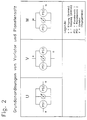
- FIG. 2 illustrates three different basic arrangements of variator and planetary gear.
- the planetary gear is a four-shaft planetary gear, which consists of two coupled simple three-shaft planetary gears.
- the overall transmission U, V or W each comprise at least one variator Var, which here in the form of a hydrostatic transmission, each comprising two hydraulic units which can be operated both as a pump and as a motor, and a four-shaft planetary transmission P, furthermore a transmission input e which at least is indirectly coupled to the drive and a transmission output a, which is at least indirectly connected to the output.
- the respective planetary gear further comprises two planetary gear sets, a first planetary gear set PS1 and a second planetary gear set PS2.
- the variator Var is connected to the two coupled shafts of the two three-shaft planetary gears.
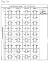
- FIG. 3a The possible basic couplings of two three-shaft planetary gear units are shown below in FIG. 3a. It does not matter whether the individual planetary gears have a positive or negative stationary gear ratio i o .
- Another 36 types can be obtained by swapping input e and output a for the W gear types. In the following, these are identified by the numbering gear type no. 2 designated.
- the stationary gear ratios i o1 and i o2 are subsequently created for all gear types, depending on the zeros i n1 and i n2 .
- the stationary gear ratio can be determined for all couplings.
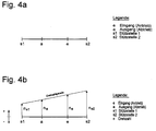
- FIG. 4 serves to explain the so-called route theory. This is based on the so-called helper bar, which is identical to the speed line in Kutzbach's speed plan. With regard to the derivation of the Kutzbach speed map, reference is made to the teaching letter for the university degree in transmission technology I No. 02 1149 01 2.
- an abstract gear is already defined. This abstract gear does not have to match the gear from the Kutzbach speed plan.
- three bar points can be combined to form a planetary gear set, each of the three bar points corresponding to one of the planetary gear elements, central wheel 1 and central wheel 2.
- the stationary gear ratio of each planetary gear set can be determined on the basis of the distance conditions on the bar. In the case of a bar with four bar points and two coupled planetary sets, two bar points of the two planetary sets must match. These two bar points then correspond to the couplings of the two planetary gear sets.
- the rotational speed can be plotted vertically on any bar point, as in FIG. Positive speeds point upwards, negative ones downwards.
- the speed behavior is represented by a straight line connecting all speed arrows with each other. This enables the speed behavior of the gearbox to be determined quickly at any bar point, ie on any shaft of the gearbox.
- i F n a / n e . If the gear ratio increases, the slope of the speed straight line decreases. At a constant input speed, it turns, for example, clockwise around the tip of arrow n e . If two speeds are known on the gearbox, the speeds of each other shaft of the gearbox can be read or calculated from the geometric relationships of the speed line.
- FIG. 5 explains the derivation of the stationary gear ratio formula using a gear type UA.
- the type of coupling and the position of input e and output a and thus also of the support points s1 and s2 (connections to the variator Var) are known from the transmission diagram.
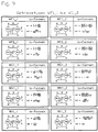
- Figures 6 to 10 contain an overview of the possible transmission types, which are created by combining the three basic arrangements U, V and W with the 36 coupling options.
- the stationary gear ratio i o1 and i o2 was determined in accordance with the steps described in FIG . From these relationships, the designer can determine the size of the additional gear from the size of the zeros in order to maintain the speed, torque and power parameters, or select the appropriate arrangement when specifying the desired additional gear ratios.
- FIG. 10 illustrates an overview of the fuel consumption as a function of the position of the zero points. This shows the following: The fuel consumption drops on all distances, the lower the first zero of the power division.
- a sink can be seen in the diagrams in the direction of the second zero.
- the earlier in the second driving range is changed, the earlier the gearbox is operated in the range of favorable efficiency.
- the power division curve increases to high values at the end of the third driving range. Because of the poor hydrostat efficiency, the losses in this driving range also increase, which has an unfavorable effect on fuel consumption.
- the power division increases in the frequently used second driving range.
- the third driving range is used less despite the decreasing power division. As a result, fuel consumption becomes unfavorably high.
- the ratio of the power divisions in the second and third driving range is optimal.
Landscapes
- Engineering & Computer Science (AREA)
- General Engineering & Computer Science (AREA)
- Mechanical Engineering (AREA)
- Transmission Devices (AREA)
- Control Of Transmission Device (AREA)
- Structure Of Transmissions (AREA)
- General Details Of Gearings (AREA)
- Retarders (AREA)
Applications Claiming Priority (2)
| Application Number | Priority Date | Filing Date | Title |
|---|---|---|---|
| DE1995122385 DE19522385A1 (de) | 1995-06-23 | 1995-06-23 | Verfahren zur Auslegung eines stufenlosen hydrostatisch-mechanischen Leistungsverzweigungsgetriebes |
| DE19522385 | 1995-06-23 |
Publications (2)
| Publication Number | Publication Date |
|---|---|
| EP0750137A2 true EP0750137A2 (fr) | 1996-12-27 |
| EP0750137A3 EP0750137A3 (fr) | 1998-06-17 |
Family
ID=7764796
Family Applications (1)
| Application Number | Title | Priority Date | Filing Date |
|---|---|---|---|
| EP96109646A Withdrawn EP0750137A3 (fr) | 1995-06-23 | 1996-06-15 | Méthode de projet d'un variateur hydromécanique continu de vitesse à division de puissance |
Country Status (2)
| Country | Link |
|---|---|
| EP (1) | EP0750137A3 (fr) |
| DE (1) | DE19522385A1 (fr) |
Cited By (1)
| Publication number | Priority date | Publication date | Assignee | Title |
|---|---|---|---|---|
| EP2098399A4 (fr) * | 2006-12-28 | 2009-12-16 | Honda Motor Co Ltd | Dispositif de puissance |
Families Citing this family (18)
| Publication number | Priority date | Publication date | Assignee | Title |
|---|---|---|---|---|
| RU2174076C1 (ru) | 2000-02-23 | 2001-09-27 | Коротков Эдуард Константинович | Универсальная механическая голономная часть передачи с бесступенчатым изменением крутящего момента (и ее варианты) |
| DE10128076A1 (de) * | 2001-06-09 | 2002-12-12 | Zahnradfabrik Friedrichshafen | Leistungsverzweigungsgetriebe |
| DE10310549B3 (de) * | 2003-03-03 | 2004-10-21 | Selle, Hans-Dieter, Dr.-Ing. | Lastschaltgetriebe mit stufenlos verstellbarem Umschlingungsgetriebe und Leistungsverzweigung |
| WO2007014706A1 (fr) | 2005-08-02 | 2007-02-08 | Gloeckler Dieter | Unite de transmission, notamment transmission multi-etagee |
| DE102014223997A1 (de) * | 2014-11-25 | 2016-05-25 | Zf Friedrichshafen Ag | Doppelt leistungsverzweigtes Getriebe mit Variator III |
| DE102015218671B4 (de) | 2015-09-29 | 2019-11-07 | Zf Friedrichshafen Ag | Getriebevorrichtung mit einer Getriebeeingangswelle mit einer Getriebeausgangswelle und mit einem Variator |
| DE102017219107B4 (de) | 2017-10-25 | 2022-05-12 | Zf Friedrichshafen Ag | Leistungsverzweigte stufenlose Getriebevorrichtung |
| DE102017219105B4 (de) | 2017-10-25 | 2022-05-12 | Zf Friedrichshafen Ag | Leistungsverzweigte stufenlose Getriebevorrichtung |
| DE102017219093B4 (de) | 2017-10-25 | 2022-05-12 | Zf Friedrichshafen Ag | Leistungsverzweigte stufenlose Getriebevorrichtung |
| DE102017219095B4 (de) | 2017-10-25 | 2022-06-02 | Zf Friedrichshafen Ag | Leistungsverzweigte stufenlose Getriebevorrichtung |
| DE102017219109B4 (de) | 2017-10-25 | 2022-05-12 | Zf Friedrichshafen Ag | Leistungsverzweigte stufenlose Getriebevorrichtung |
| DE102017219098B4 (de) | 2017-10-25 | 2022-05-12 | Zf Friedrichshafen Ag | Leistungsverzweigte stufenlose Getriebevorrichtung |
| DE102017219097B4 (de) | 2017-10-25 | 2022-05-12 | Zf Friedrichshafen Ag | Leistungsverzweigte stufenlose Getriebevorrichtung |
| DE102017219108B4 (de) | 2017-10-25 | 2022-05-12 | Zf Friedrichshafen Ag | Leistungsverzweigte stufenlose Getriebevorrichtung |
| DE102017219102B4 (de) | 2017-10-25 | 2022-05-12 | Zf Friedrichshafen Ag | Leistungsverzweigte stufenlose Getriebevorrichtung |
| DE102017219106B4 (de) | 2017-10-25 | 2022-05-12 | Zf Friedrichshafen Ag | Leistungsverzweigte stufenlose Getriebevorrichtung |
| DE102017219100B4 (de) | 2017-10-25 | 2022-05-12 | Zf Friedrichshafen Ag | Leistungsverzweigte stufenlose Getriebevorrichtung |
| DE102022208594B3 (de) | 2022-08-18 | 2023-07-27 | Zf Friedrichshafen Ag | Leistungsverzweigtes stufenloses Getriebe |
Family Cites Families (4)
| Publication number | Priority date | Publication date | Assignee | Title |
|---|---|---|---|---|
| US3470769A (en) * | 1967-10-16 | 1969-10-07 | Gen Motors Corp | Input-split-power,output-split-power,compound-split-power,power train |
| DE1755161B1 (de) * | 1968-04-06 | 1970-04-30 | Rheinstahl Huettenwerke Ag | Regeleinrichtung für ein durch eine Brennkraftmachine angetriebenes hydrostatisch-mechanisches Überlagerungsgetriebe für Fahrzeuge |
| JPS5424066B2 (fr) * | 1972-04-28 | 1979-08-18 | ||
| CN1019680B (zh) * | 1987-11-03 | 1992-12-30 | 罗明远 | 功率分流无级变速传动系统 |
-
1995
- 1995-06-23 DE DE1995122385 patent/DE19522385A1/de not_active Withdrawn
-
1996
- 1996-06-15 EP EP96109646A patent/EP0750137A3/fr not_active Withdrawn
Cited By (2)
| Publication number | Priority date | Publication date | Assignee | Title |
|---|---|---|---|---|
| EP2098399A4 (fr) * | 2006-12-28 | 2009-12-16 | Honda Motor Co Ltd | Dispositif de puissance |
| US8226513B2 (en) | 2006-12-28 | 2012-07-24 | Honda Motor Co., Ltd. | Power plant |
Also Published As
| Publication number | Publication date |
|---|---|
| DE19522385A1 (de) | 1997-01-09 |
| EP0750137A3 (fr) | 1998-06-17 |
Similar Documents
| Publication | Publication Date | Title |
|---|---|---|
| EP0750137A2 (fr) | Méthode de projet d'un variateur hydromécanique continu de vitesse à division de puissance | |
| DE102014214008B4 (de) | Mehrganggetriebe | |
| DE69113631T2 (de) | Getriebe mit toroidumlaufbahn und rollreibungskraftübertrang. | |
| EP0195452B1 (fr) | Transmission hybride commutable sous charge, réglable continûment à division de puissance et commande par groupes-relais | |
| EP0081696A1 (fr) | Transmission hydromécanique avec division de puissance à l'entrée | |
| DE3026219A1 (de) | Antriebsaggregat mit einer antriebsmaschine und einem schwungrad | |
| DE2328353C3 (de) | Stufenloses, leistungsverzweigendes hydrostatisch-mechanisches Getriebe | |
| DE2525888A1 (de) | Leistungsverzweigtes getriebe | |
| EP0683875A1 (fr) | Transmission hydrostatique variable a division de puissance | |
| DE10047398A1 (de) | Getriebesynthese mit stufenlosen und konstanten Getriebemodulen | |
| EP0628751A1 (fr) | Transmission de changement de vitesse sous charge avec variation continue hydrostatique de rapports | |
| EP0168569A1 (fr) | Transmission pour véhicule à moteur avec un variateur continu de vitesse à courroie | |
| EP1704348B1 (fr) | Boite hydrostatique mecanique a derivation de puissance | |
| DE3543635A1 (de) | Getriebeanordnung | |
| DE10122823B4 (de) | Leistungsverzweigungsgetriebe | |
| DE10250480A1 (de) | Automatisiertes Mehrgang-Schaltgetriebe | |
| EP0291525B1 (fr) | Mecanisme de roulement et de direction progressif pour vehicules a chenilles | |
| EP0731290B1 (fr) | Transmission à arbres intermédiaires | |
| DE2502309A1 (de) | Regelbares zweiwege-getriebe | |
| EP0728962B1 (fr) | Transmission mécanique-hydrostatique | |
| EP0397804B1 (fr) | Boite de vitesses couplable sous charge a rapport variable en continu | |
| DE102020203391A1 (de) | Leistungsverzweigtes stufenloses Getriebe | |
| DE8018579U1 (de) | Antriebsaggregat mit einer Antriebsmaschine und einem Schwungrad | |
| DE3538343A1 (de) | Getriebeanordnung fuer fahrzeuge, insbesondere kraftfahrzeuge | |
| DE4226576C2 (de) | Zahnräderwechselgetriebe für ein Kraftfahrzeug |
Legal Events
| Date | Code | Title | Description |
|---|---|---|---|
| PUAI | Public reference made under article 153(3) epc to a published international application that has entered the european phase |
Free format text: ORIGINAL CODE: 0009012 |
|
| AK | Designated contracting states |
Kind code of ref document: A2 Designated state(s): DE FR GB IT SE |
|
| PUAL | Search report despatched |
Free format text: ORIGINAL CODE: 0009013 |
|
| AK | Designated contracting states |
Kind code of ref document: A3 Designated state(s): DE FR GB IT SE |
|
| 17P | Request for examination filed |
Effective date: 19980707 |
|
| RAP1 | Party data changed (applicant data changed or rights of an application transferred) |
Owner name: VOITH TURBO BETEILIGUNGS GMBH |
|
| 17Q | First examination report despatched |
Effective date: 19990930 |
|
| STAA | Information on the status of an ep patent application or granted ep patent |
Free format text: STATUS: THE APPLICATION IS DEEMED TO BE WITHDRAWN |
|
| 18D | Application deemed to be withdrawn |
Effective date: 20000411 |