EP0750188B1 - Appareil et méthode pour analyser l'état physiologique d'un organisme - Google Patents
Appareil et méthode pour analyser l'état physiologique d'un organisme Download PDFInfo
- Publication number
- EP0750188B1 EP0750188B1 EP95304613A EP95304613A EP0750188B1 EP 0750188 B1 EP0750188 B1 EP 0750188B1 EP 95304613 A EP95304613 A EP 95304613A EP 95304613 A EP95304613 A EP 95304613A EP 0750188 B1 EP0750188 B1 EP 0750188B1
- Authority
- EP
- European Patent Office
- Prior art keywords
- organism
- sample
- detection unit
- liquid
- circumstance
- Prior art date
- Legal status (The legal status is an assumption and is not a legal conclusion. Google has not performed a legal analysis and makes no representation as to the accuracy of the status listed.)
- Expired - Lifetime
Links
- 230000035790 physiological processes and functions Effects 0.000 title claims description 20
- 238000000034 method Methods 0.000 title claims description 13
- 239000007788 liquid Substances 0.000 claims description 35
- 238000001514 detection method Methods 0.000 claims description 33
- 230000012010 growth Effects 0.000 claims description 22
- 238000004458 analytical method Methods 0.000 claims description 20
- 238000001228 spectrum Methods 0.000 claims description 17
- 239000000523 sample Substances 0.000 description 96
- 238000002595 magnetic resonance imaging Methods 0.000 description 24
- 239000007789 gas Substances 0.000 description 19
- 241000196324 Embryophyta Species 0.000 description 11
- 239000000126 substance Substances 0.000 description 11
- 230000001066 destructive effect Effects 0.000 description 8
- 238000010183 spectrum analysis Methods 0.000 description 6
- 230000008859 change Effects 0.000 description 5
- 230000004962 physiological condition Effects 0.000 description 5
- 206010020649 Hyperkeratosis Diseases 0.000 description 4
- 230000035784 germination Effects 0.000 description 4
- 244000005700 microbiome Species 0.000 description 4
- XLYOFNOQVPJJNP-UHFFFAOYSA-N water Substances O XLYOFNOQVPJJNP-UHFFFAOYSA-N 0.000 description 4
- 241000209140 Triticum Species 0.000 description 3
- 235000021307 Triticum Nutrition 0.000 description 3
- 238000009395 breeding Methods 0.000 description 3
- 230000001488 breeding effect Effects 0.000 description 3
- 239000003990 capacitor Substances 0.000 description 3
- 150000001875 compounds Chemical class 0.000 description 3
- 238000003745 diagnosis Methods 0.000 description 3
- 125000004435 hydrogen atom Chemical class [H]* 0.000 description 3
- 230000004060 metabolic process Effects 0.000 description 3
- 230000003068 static effect Effects 0.000 description 3
- 238000002059 diagnostic imaging Methods 0.000 description 2
- 238000003384 imaging method Methods 0.000 description 2
- 230000006872 improvement Effects 0.000 description 2
- 238000012423 maintenance Methods 0.000 description 2
- 239000000463 material Substances 0.000 description 2
- 239000000203 mixture Substances 0.000 description 2
- 238000001303 quality assessment method Methods 0.000 description 2
- IJGRMHOSHXDMSA-UHFFFAOYSA-N Atomic nitrogen Chemical compound N#N IJGRMHOSHXDMSA-UHFFFAOYSA-N 0.000 description 1
- 241000206602 Eukaryota Species 0.000 description 1
- 238000012307 MRI technique Methods 0.000 description 1
- 206010028980 Neoplasm Diseases 0.000 description 1
- OAICVXFJPJFONN-UHFFFAOYSA-N Phosphorus Chemical compound [P] OAICVXFJPJFONN-UHFFFAOYSA-N 0.000 description 1
- 229920002472 Starch Polymers 0.000 description 1
- 238000010521 absorption reaction Methods 0.000 description 1
- 239000003708 ampul Substances 0.000 description 1
- 230000031018 biological processes and functions Effects 0.000 description 1
- 230000000740 bleeding effect Effects 0.000 description 1
- 238000007664 blowing Methods 0.000 description 1
- 238000006243 chemical reaction Methods 0.000 description 1
- 238000010276 construction Methods 0.000 description 1
- 238000000354 decomposition reaction Methods 0.000 description 1
- 238000011161 development Methods 0.000 description 1
- 230000018109 developmental process Effects 0.000 description 1
- 229910001873 dinitrogen Inorganic materials 0.000 description 1
- 230000001747 exhibiting effect Effects 0.000 description 1
- 239000004744 fabric Substances 0.000 description 1
- 125000000524 functional group Chemical group 0.000 description 1
- 239000011521 glass Substances 0.000 description 1
- 239000001963 growth medium Substances 0.000 description 1
- 239000011796 hollow space material Substances 0.000 description 1
- 239000001257 hydrogen Substances 0.000 description 1
- 229910052739 hydrogen Inorganic materials 0.000 description 1
- 238000003780 insertion Methods 0.000 description 1
- 230000037431 insertion Effects 0.000 description 1
- 238000007689 inspection Methods 0.000 description 1
- 230000033001 locomotion Effects 0.000 description 1
- 210000001161 mammalian embryo Anatomy 0.000 description 1
- 230000002503 metabolic effect Effects 0.000 description 1
- 230000035699 permeability Effects 0.000 description 1
- 229910052698 phosphorus Inorganic materials 0.000 description 1
- 239000011574 phosphorus Substances 0.000 description 1
- 230000002265 prevention Effects 0.000 description 1
- 238000009877 rendering Methods 0.000 description 1
- 238000011160 research Methods 0.000 description 1
- 230000029058 respiratory gaseous exchange Effects 0.000 description 1
- 230000035939 shock Effects 0.000 description 1
- 238000011895 specific detection Methods 0.000 description 1
- 235000019698 starch Nutrition 0.000 description 1
- 239000008107 starch Substances 0.000 description 1
- 239000000725 suspension Substances 0.000 description 1
- 238000012360 testing method Methods 0.000 description 1
- 238000004804 winding Methods 0.000 description 1
Images


Classifications
-
- G—PHYSICS
- G01—MEASURING; TESTING
- G01R—MEASURING ELECTRIC VARIABLES; MEASURING MAGNETIC VARIABLES
- G01R33/00—Arrangements or instruments for measuring magnetic variables
- G01R33/20—Arrangements or instruments for measuring magnetic variables involving magnetic resonance
- G01R33/28—Details of apparatus provided for in groups G01R33/44 - G01R33/64
- G01R33/30—Sample handling arrangements, e.g. sample cells, spinning mechanisms
-
- G—PHYSICS
- G01—MEASURING; TESTING
- G01R—MEASURING ELECTRIC VARIABLES; MEASURING MAGNETIC VARIABLES
- G01R33/00—Arrangements or instruments for measuring magnetic variables
- G01R33/20—Arrangements or instruments for measuring magnetic variables involving magnetic resonance
- G01R33/28—Details of apparatus provided for in groups G01R33/44 - G01R33/64
- G01R33/32—Excitation or detection systems, e.g. using radio frequency signals
- G01R33/34—Constructional details, e.g. resonators, specially adapted to MR
- G01R33/34046—Volume type coils, e.g. bird-cage coils; Quadrature bird-cage coils; Circularly polarised coils
- G01R33/34053—Solenoid coils; Toroidal coils
-
- G—PHYSICS
- G01—MEASURING; TESTING
- G01R—MEASURING ELECTRIC VARIABLES; MEASURING MAGNETIC VARIABLES
- G01R33/00—Arrangements or instruments for measuring magnetic variables
- G01R33/20—Arrangements or instruments for measuring magnetic variables involving magnetic resonance
- G01R33/44—Arrangements or instruments for measuring magnetic variables involving magnetic resonance using nuclear magnetic resonance [NMR]
- G01R33/46—NMR spectroscopy
- G01R33/465—NMR spectroscopy applied to biological material, e.g. in vitro testing
-
- Y—GENERAL TAGGING OF NEW TECHNOLOGICAL DEVELOPMENTS; GENERAL TAGGING OF CROSS-SECTIONAL TECHNOLOGIES SPANNING OVER SEVERAL SECTIONS OF THE IPC; TECHNICAL SUBJECTS COVERED BY FORMER USPC CROSS-REFERENCE ART COLLECTIONS [XRACs] AND DIGESTS
- Y10—TECHNICAL SUBJECTS COVERED BY FORMER USPC
- Y10T—TECHNICAL SUBJECTS COVERED BY FORMER US CLASSIFICATION
- Y10T436/00—Chemistry: analytical and immunological testing
- Y10T436/24—Nuclear magnetic resonance, electron spin resonance or other spin effects or mass spectrometry
Definitions
- the present invention relates to an apparatus and a method for analyzing the physiological state of a living organism of procaryotes and eucaryotes, for example, plants, seeds, tissues, calluses and microorgamisms, in a dynamic or static way, by means of the technique of magnetic resonance imaging (denoted hereinafter by the acronym MRI).
- MRI magnetic resonance imaging
- MRI Magnetic resonance
- the MRI technique permits to realize an image-visualized diagnosis and a spectral analysis by making use of the phenomenon of MR of, for example, hydrogen atom nucleus, allowing thus a non-destructive observation of the internal structure and the chemical composition of a sample to be inspected. Due to the permeability through materials and capability of obtaining the spectrum corresponding to the existing functional groups in the material, MRI is used also for other analytical purposes including a non-destructive histological observation and compositional analysis of a sample. MRI apparatuses to be used for such non-destructive quality assessments and analyses of samples are also based on the same principle as the MRI apparatuses for the medical diagnosis, so that both have nearly the same construction.
- a cradle carrying a sample holder charged with a sample of the organism is placed within the hollow core space of the stationary magnetic field generator at a prescribed position thereof and is fixed to the gradient magnetic field generator. Then, the RF-emission-reception set accommodated in a cylindrical probe placed within the cradle is tuned at the resonating frequency using tuner shunks. Due to the insertion of the sample, the cylindrical probe and the cradle into the hollow core space, some disturbance in the static magnetic field occurs, which is removed by shimming to homogenize the magnetic field.
- a gradient magnetic field is generated by energizing the coil in the gradient magnetic field generator, while at the same time actuating the RF coil of the RF-emission-reception set to emit RF pulses to the sample via the RF coil to cause a magnetic resonance thereof.
- These MR signals are received by the RF coil upon cessation of emission of the RF pulse and are processed by a computer into corresponding image which is visualized on a display.
- these conventional MRI -apparatuses are not adapted for analyzing the physiological state of organisms, such as the state of growth of a sample of an organism, for example, a plant, seed, tissue, callus or a microorganism, in particular, for analyzing the course of change thereof, so as to attain a successive quality assessment and chemical analysis, since the conventional apparatuses are based on the same principle as those for use in medical diagnoses.
- An object of the present invention is to provide an apparatus and a method for analyzing the physiological state of an organism, by which successive analyses of the physiological state of an organism including the state of growth of a growing sample of the organism can be realized for the internal structure thereof in a non-destructive manner.
- an apparatus for analysing the physiological state of an organism, the apparatus being provided in accordance with claim 1.
- the apparatus for analysing the physiological state of an organism is constructed by incorporating a specific detection unit and a circumstance regulator in a commercially available conventional MRI apparatus, with which the contemplated analysis of the physiological state of the organism is carried out by maintaining a sample of the organism in a preset circumstance and producing an MR image and/or spectrum of the organism.
- the apparatus according to the present invention can be designed to be adapted to perform the analysis of the growth state of an organism by growing a sample of the organism and to inspect the sample organism by MR images and/or spectra obtained during the growth of the sample organism.
- sample as used herein is meant any sample of uecaryotic or procaryotic organisms including plants, seeds, tissues, calluses and microorganisms.
- the RF-emission-reception set For the MRI apparatus composed of the magnetic field generator, the RF-emission-reception set and so on, commercial articles may be employed.
- the stationary magnetic field generating element of the magnetic field generator it is preferable to use a superconducting magnet designed in a horizontally laid cylindrical form having an axially extending hollow core space.
- the gradient magnetic field generating element of the magnetic field generator is designed to build up a magnetic field with gradient components in the x-, y- and z-coordinate directions.
- the RF-emission-reception set has an RF coil and may be designed either in a form in which one and the same element is used as the emitter and as the receiver or in a form in which separate elements are used as the emitter and receiver.
- the detection unit is charged with a sample of the organism and is then placed within the hollow core space of the magnetic field generator, whereupon the sample is held in a preset circumstance of a definite atmosphere, temperature, humidity and so on by means of the circumstance regulator.
- the RF-emission-reception set is operated to actuate the RF coil to emit RF pulses to the sample and to receive the resulting magnetic resonance signals from the sample, which are processed into corresponding image and/or spectrum to attain the contemplated analysis of the physiological state of the sample organism.
- the detection unit charged with a sample of the organism is placed within the hollow core space of the magnetic field generator, whereupon the sample is held in a suitable growing circumstance by adjusting the rates of the gas and liquid feeds and the temperature by means of the circumstance regulator to grow the sample organism.
- the RF-emission-reception set is operated either successively or intermittently to actuate the RF coil to emit RF pulses to the sample and to receive the resulting magnetic resonance signals from the sample, which are processed into corresponding image and/or spectrum to attain the contemplated static or dynamic analysis of the physiological state of the sample organism.
- the histomorphological analysis of physiological variation, change in the metabolism and so on, incidental to a specific circumstance or condition of growth of an organism can be attained by analyzing the MR image in combination with the spectrum of a specific chemical component, such as a sugar, to thereby assess the germination characteristic and cultivation condition of an agricultural plant, in order to contribute to breeding of culture plants and to improvement of culture condition.
- a specific chemical component such as a sugar
- the physiological state of the organism can be analyzed successively in a non-destructive way with a sample of the organism from an MR image and/or spectrum thereof, by arranging an RF-emission-reception set and a detection unit including the sample organism within the hollow core space of the magnetic field generator and maintaining the sample organism in a preset circumstance using a circumstance regulator.
- the state of growth of the organism can be analyzed successively in a non-destructive way with a sample of the organism from an MR image and/or spectrum thereof, by arranging, within the hollow core space of the magnetic field generator, an RF-emission-reception set and a detection unit including the sample organism and growing the sample organism while maintaining it in a preset circumstance using a circumstance regulator, whereby it is possible to analyze histomorphological variation and change in the metabolism of the sample organism incidental to the growth thereof.
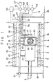
- Figs. 1 - 4 show an embodiment of the apparatus according to the present invention for analyzing the state of growth of a sample organism, in which Fig. 1 is a vertical section, Fig. 2 is a part thereof in an enlarged view, Fig. 3 is a section along the line A-A of Fig. 2 and Fig. 4 is a plan of the sample holder.
- the growth state analyzing apparatus is indicated by the numeral 1, in which a magnetic field generator 2 of cylindrical form accommodates within its hollow core space 3 a detection unit 4 and an RF-emission-reception set 5.
- the detection unit 4 is so designed that a predetermined growing circumstance is maintained by a circumstance regulator 6.
- the magnetic field generator 2 is composed of a stationary magnetic field generating coil 2a constituted of a horizontally laid cylindrical superconducting magnet and a gradient magnetic field generating coil 2b disposed inside the coil 2a coaxially therewith, in which the hollow core space 3 is formed and the entire body is supported on stands 7.
- the RF-emission-reception set 5 includes capacitors, such as a trimmer capacitor, a chipping capacitor and so on, accommodated therein. From one side end of the RF-emission-reception set 5, lead wires extend out to connect with an RF coil 8 disposed within the detection unit 4 and wound around the sample holder 11 and, from the other side end, tuner shunks 9 project out of the magnetic field generator 2.
- the magnetic field generator 2 and the RF-emission-reception set 5 constitute an MRI arrangement which operates to produce imaging signals to be processed into corresponding image and/or spectrum by a computer, a detailed depiction of which is omitted here.
- the detection unit 4 is constructed in a form of a hollow casing, as shown in Figs. 2 - 4, and includes, within the internal space 12 thereof, the sample holder 11 wound by the RF coil 8 around it.
- an opening 13 for guiding the sample holder 11 into the space 12 and an opening 14 for guiding tubes into the space 12, respectively, are provided and a warm air introducing tube 15 which opens into the internal space 12 projects out of the ceiling of the detection unit.
- the sample holder 11 has a cylindrical form and includes therein, in an adjoining relation, a sample receiving pocket 21 for receiving the sample 16 and a sample arrester receiving pocket 22 for receiving a sample arrester 17. Beneath them, a pad 18 is provided and held in a pad holding pocket 23 formed in the lower part of the sample holder 11. Separately and spaced from them, a standard substance receiving pocket 24 extending radially of the sample holder is provided for receiving a standard substance 19.
- One end part of the sample holder 11 is provided with a liquid feed tube receiving hole 25 and a gas feed tube receiving hole 26 and, in addition, a liquid drain tube receiving hole 27. They serve for receiving a liquid feed tube 31, a gas feed tube 32 and a liquid drain tube 33 for draining the spent liquid via the pad holding pocket 23, respectively, which are guided through the opening 14.
- the sample holder 11 Around the outer circumference of the sample holder 11, there are formed two circumferential ribs 34 each at a portion near the end.
- the sample holder 11 is sleeved by a longitudinally split sleeve 35 capable of resiliently tightening the sample holder and serves for holding the sample 16, the sample arrester 17, the pad 18 and the standard substance 19 in each respective receiving pocket.
- the ribs are provided in order to prevent falling off of the sleeve 35.
- the RF coil 8 is arranged by winding around the sleeve 35 to fasten it to hold the sample holder fixedly, though it is shown in the Drawing in a state separate from the sleeve 35.
- the detection unit 4 and the RF-emission-reception set 5 are combined together integrally and are fixed to an air feed duct 36 served as a supporting beam by suspension rods 41, 42 and fixing screws 45 via guide members 43, 44.
- the air feed duct 36 is mounted on a pair of supporting pillars 38 using each a fixing joint 37 so as to permit adjustment of the elevation and the horizontal position.
- the circumstance regulator 6 is composed of the air feed duct 36 connected with the warm air introducing tube 15, a blower 46 for supplying the air feed duct 36 with a warm air or cold air, a temperature regulator 47, the liquid feed tube 31, a liquid feed pump 48 connected with the liquid feed tube 31, a gas feed tube 32, a gas feed blower 49 connected with the gas feed tube 32, the liquid drain tube 33, the liquid drain pump 50 connected with the liquid drain tube 33, thermosensors 51 and 52 disposed in the detection unit 4 and in the gas feed duct 36, and a control unit 53.
- Suspending members 54 serve for supporting the tubes 31, 32 and 33 by suspending them from the gas feed duct 36.
- the sample receiving pocket 21 of the unsheathed sample holder 11 is charged with a sample 16 of the organism, for example, a seed of a plant (a seed of wheat in this Example), and then, the sample arrester 17 (a short soft plastic tube) is placed in the arrester receiving pocket 22 to arrest the seed 16 to avoid any vibration thereof.
- a water-permeable pad 18 made of, for example, unwoven cloth is inserted in the pad receiving pocket 23 and the standard substance receiving pocket 24 is charged with a standard substance 19, such as a glass ampule filled with water as the standard substance.
- the sample holder 11 is sheathed with the sleeve 35 and the so assembled sample holder 11 is placed and fixed on the internal circumference of the RF coil 8.
- the RF coil now carrying the sample holder 11 is guided into the hollow space 12 of the detection unit 4 from the opening 13. Then, the liquid feed tube 31, the gas feed tube 32 and the liquid drain tube 33 are inserted into the detection unit 4 through the opening 14 by inserting them in the liquid feed tube receiving hole 25, in the gas feed tube receiving hole 26 and in the liquid drain tube receiving hole 27 of the sample holder 11, respectively, to build up the path connection.
- the gas feed duct 36 is guided through the guide members 43, 44 and through the suspending members 54 and is fixed thereto at each adequate position by fixing screws 45.
- the resulting assemblage is then interted into the core space 3 of the magnetic field generator 2 together with the detection unit 4 and the RF-emission-reception set 5 and is fixed on the pair of supporting pillars 38 under adjustment of the elevation and the horizontal position thereof by the fixing joints 37.
- the apparatus is operated by actuating the control unit 53 so as to control the blower 46, the temperature regulator 47 and the pumps 48, 49 and 50 to maintain the circumstance in the sample receiving pocket 21 of the sample holder 11 in a predetermined growing condition, in order to grow the living sample 16 of the organism in the sample holder.
- the temperature regulator 47 is controlled in accordance with the control signals from the heat sensors 51 and 52 corresponding to the temperatures of the detection unit 4 and of the air feed duct 36, so as to adjust the blowing rate and the temperature of warm or cold air fed by the blower 46, in order to maintain the circumstance in the detection unit 4 in an adequate condition.
- the air delivered by the blower 46 enters the detection unit 4 from the air feed duct 36 via the warm air introducing tube 15 and is discharged out of the detection unit 4 through the opening 13 and the opening 14 into the hollow core space 3 of the magnetic field generator 2.
- the feed gas such as air, nitrogen gas or the like is supplied to the sample holder 11 via the gas feed tube 32 to maintain a definite aerobic or anaerobic atmosphere in the sample receiving pocket 21.
- the sample holder 11 is supplied with a liquid of a composition requisite for growing the sample organism, such as water, a culture medium or the like, via the liquid feed tube 31, to thereby soak the pad 18 therewith, while attaining at the same time maintenance of a constant humidity thereof.
- the superfluous portion of the liquid is drained by the liquid drain pump 50 through the liquid drain tube 33.
- the gas feed supplied from the gas feed tube 32 is discharged out through the existing gaps.
- the sample holder 11 is adjusted internally in a definite condition of the atmosphere, temperature and humidity, whereby the sample 16 can grow with pertinent respiration and water intake.
- the sample 16 of an organism can be examined successively on the MR image and/or spectrum to thereby attain an analysis of the physiological condition, in particular, the growth state of the sample organism 16 under a specific circumstance.
- the magnetic field generator 2 is actuated so as to build up a stationary magnetic field within the hollow core space thereof by energizing the stationary magnetic field generating coil 2a and to superpose thereon a gradient magnetic field by energizing the gradient magnetic field generating coil 2b, whereupon the tuning is effected by manipulating the tuner shunks 9 with shimming.
- the RF-emission-reception set 5 is actuated so as to cause emission of RF pulses from the RF coil 8, whereupon the resulting MR signals emitted from the sample 16 and from the standard substance 19 are compared and processed and are reconstructed into the corresponding MR image and/or spectrum.
- the MR image and the spectrum of a sample organism can be obtained in a specific slice section of the sample and such slice section can be selected and shifted voluntarily in a continuous or intermittent manner in the MRI ex animation of the growth state of the sample organism, so that a dynamic analysis of the physiological condition of living organism can be realized.
- MRI a spectral analysis of a specific compound in the sample organism is possible.
- the apparatus it is possible by the apparatus according to the present invention to examine the sample organism by a combination of an MRI analysis with a spectral analysis of a specific compound, such as a sugar, in the sample, to thereby attain a combined assessment from the observation of changes in the histomorphological and metabolic aspects of the sample with respect to, for example, the germination characteristic, pertinent cultivation condition and so on, to contribute to the development of breeding and improvement of cultivation condition of agricultural plants etc.
- a specific compound such as a sugar
- the apparatus described above allows prevention of any influence of mechanical motion by, for example, pumps and blowers, on the resulting MRI image, since the detection unit 4 and the RF-emission-reception set 5 are disposed within the hollow core space 3 of the magnetic field generator 2 and the sample organism is maintained in a definite growing circumstance by effecting the supply of gas and liquid isolatedly from the magnetic field generator 2.
- the warm air or cold air is supplied through the gas feed duct 36 served as the supporting beam, so that any vibrational influence on the MR image can be avoided even upon a high-duty operation of the blowers, permitting thus an efficient gas supply with a stable maintenance of constant temperature of the growth circumstance.
- the MRI observation can be effected repeatedly or successively without incorporating any additional operation of the tuning and shimming during the observation, after such an operation has been performed once at the start of the MRI observation.
- any shock occurring upon the introduction of the stationary magnetic field can never be transmitted to the sample 16, so that no disturbance in the MR signals is brought about and, thus, an image or spectrum of high accuracy can be obtained.
- the MRI observation of a sample organism can be effected succeedingly, while maintaining a constant circumstance, so that it is possible to realize a successive analysis of the physiological condition of a sample organism in a non-destructive way and, thus, to obtain temporally succeeding observation data for a programmed breeding and for improving the cultivation condition.
- a sample of a plant exhibiting superior ability in the growth of root may be assessed to be superior in the erectability of the seedling and in the ability for actively striking the root upon direct planting. It is also possible to cultivate the sample, such as a germinated seed, which has been assessed to be ranked as superior by such MRI observation, in order to multiply it.
- the apparatus and the method according to the present invention it is possible also to analyze the physiological condition of a sample of not only seeds of plants, but also other organisms such as tissues, calluses and microorganisms, by performing a series of observations by a combination of MRI analysis with MR spectral analysis of a pertinent compound in the course of the physiological change.
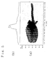
- Fig. 5a shows the MR image of a seed of a wheat (Norin No. 61) after 28 hours' growing at 30°C and Fig. 5b illustrates the corresponding MR spectrum.
Landscapes
- Physics & Mathematics (AREA)
- Condensed Matter Physics & Semiconductors (AREA)
- General Physics & Mathematics (AREA)
- Magnetic Resonance Imaging Apparatus (AREA)
- Apparatus Associated With Microorganisms And Enzymes (AREA)
- Investigating Or Analyzing Materials By The Use Of Magnetic Means (AREA)
Claims (4)
- Dispositif pour analyser l'état physiologique d'un organisme, comprenant:un générateur de champ magnétique (2) pour créer un champ magnétique stationnaire et un champ magnétique à gradient à l'intérieur d'un espace (3) central, creux, du générateur; etun poste (5) d'émission-réception RF ayant une bobine RF (8) située à l'intérieur dudit espace central creux (3), pour émettre des impulsions RF vers un organisme échantillon maintenu dans l'espace central, et recevoir les signaux résultants, de résonance magnétique de l'organisme échantillon, caractérisé en ce que le dispositif comprend en outre une unité de détection (4) formée par une enceinte creuse entourant la bobine RF (8), et disposée dans ledit espace central creux, et adaptée pour que l'organisme échantillon soit chargé à l'intérieur; etun régulateur de condition (6), couplé à l'enceinte de l'unité de détection par un conduit (36) d'amenée d'air, un tuyau (31) d'amenée de liquide, un tuyau (32) d'amenée de gaz, et un tuyau (33) de drainage de liquide, de manière à maintenir l'organisme échantillon placé à l'intérieur de l'unité de détection dans une condition présélectionnée en fournissant un air contrôlé en température dans l'enceinte de l'unité de détection via le conduit (36) d'amenée d'air, en fournissant un liquide via le tuyau (31) d'amenée de liquide, en fournissant un gaz via le tuyau (32) d'amenée de gaz, et en drainant le liquide via le tuyau (33) de drainage de liquide.
- Dispositif de la revendication 1, dans lequel l'unité de détection est adaptée pour être chargée avec l'organisme échantillon en vue de sa culture.
- Procédé pour analyser l'état physiologique d'un organisme, comprenant les étapes consistant à:placer un organisme échantillon à l'intérieur de l'espace central creux (3) d'un générateur de champ magnétique (2); etmettre en service un poste (5) d'émission-réception RF ayant une bobine RF, de manière à émettre des impulsions RF vers l'organisme échantillon, et à recevoir les signaux résultants, de résonance magnétique de l'organisme échantillon, via la bobine RF; etconvertir les signaux en image et/ou spectre correspondants pour ainsi obtenir une analyse de l'état physiologique de l'organisme échantillon, caractérisé en ce qu'une unité de détection (4) est chargée intérieurement de l'organisme échantillon, et est placée à l'intérieur de l'espace central creux, l'unité de détection (4) étant formée par une enceinte creuse entourant la bobine RF (8); et en ce que l'organisme échantillon est maintenu à l'intérieur de ladite unité de détection (4) dans une condition présélectionnée, en amenant un régulateur de condition (6), couplé à l'enceinte de l'unité de détection par un conduit (36) d'amenée d'air, un tuyau (31) d'amenée de liquide, un tuyau (32) d'amenée de gaz, et un tuyau (33) de drainage de liquide, à fournir un air contrôlé en température dans l'enceinte de l'unité de détection (4) via le conduit (36) d'amenée d'air, à fournir un liquide via le tuyau (31) d'amenée de liquide, à fournir un gaz via le tuyau (32) d'amenée de gaz, et à drainer le liquide via le tuyau (33) de drainage du liquide.
- Procédé de la revendication 3, dans lequel l'organisme échantillon est maintenu dans l'unité de détection (4) dans une condition présélectionnée de culture par le régulateur de condition (6) de manière à cultiver l'échantillon de l'organisme, et dans lequel les signaux de résonance magnétique résultants sont convertis en image et/ou spectre correspondants, pour ainsi obtenir une analyse de l'état de croissance de l'organisme échantillon.
Applications Claiming Priority (3)
| Application Number | Priority Date | Filing Date | Title |
|---|---|---|---|
| JP15813895A JP3505566B2 (ja) | 1995-06-23 | 1995-06-23 | 生理状態解析装置および方法 |
| JP158138/95 | 1995-06-23 | ||
| JP15813895 | 1995-06-23 |
Related Child Applications (1)
| Application Number | Title | Priority Date | Filing Date |
|---|---|---|---|
| EP02026443 Division | 2002-11-27 |
Publications (2)
| Publication Number | Publication Date |
|---|---|
| EP0750188A1 EP0750188A1 (fr) | 1996-12-27 |
| EP0750188B1 true EP0750188B1 (fr) | 2003-08-20 |
Family
ID=15665105
Family Applications (1)
| Application Number | Title | Priority Date | Filing Date |
|---|---|---|---|
| EP95304613A Expired - Lifetime EP0750188B1 (fr) | 1995-06-23 | 1995-06-30 | Appareil et méthode pour analyser l'état physiologique d'un organisme |
Country Status (4)
| Country | Link |
|---|---|
| US (1) | US5759797A (fr) |
| EP (1) | EP0750188B1 (fr) |
| JP (1) | JP3505566B2 (fr) |
| DE (1) | DE69531540T2 (fr) |
Cited By (6)
| Publication number | Priority date | Publication date | Assignee | Title |
|---|---|---|---|---|
| US7832143B2 (en) | 2004-08-26 | 2010-11-16 | Monsanto Technology Llc | High throughput methods for sampling seeds |
| US7941969B2 (en) | 2004-08-26 | 2011-05-17 | Monsanto Technology Llc | Methods of seed breeding using high throughput nondestructive seed sampling |
| US8245439B2 (en) | 2006-03-02 | 2012-08-21 | Monsanto Technology Llc | Automated high-throughput seed sampler and methods of sampling, testing and bulking seeds |
| US8401271B2 (en) | 2007-05-31 | 2013-03-19 | Monsanto Technology Llc | Seed sorter |
| US8539713B2 (en) | 2006-03-02 | 2013-09-24 | Monsanto Technology Llc | Automated contamination-free seed sampler and methods of sampling, testing and bulking seeds |
| CN108491684A (zh) * | 2018-01-23 | 2018-09-04 | 中国农业大学 | 一种植物电信号分析方法及系统 |
Families Citing this family (15)
| Publication number | Priority date | Publication date | Assignee | Title |
|---|---|---|---|---|
| US7367155B2 (en) * | 2000-12-20 | 2008-05-06 | Monsanto Technology Llc | Apparatus and methods for analyzing and improving agricultural products |
| PT1499545E (pt) | 2002-04-04 | 2008-03-20 | Monsanto Technology Llc | Sistema automatizado de triagem, pesagem e recolha de matéria particulada |
| JP2003329756A (ja) * | 2002-05-08 | 2003-11-19 | Hitachi Ltd | 超高感度核磁気共鳴イメージング装置 |
| GB0212581D0 (en) * | 2002-05-30 | 2002-07-10 | Imp College Innovations Ltd | Medical analysis device |
| BRPI0414708B1 (pt) | 2003-09-23 | 2019-05-14 | Monsanto Technology Llc | Sistema e método para processamento de sementes. |
| AR050469A1 (es) | 2004-08-26 | 2006-10-25 | Monsanto Technology Llc | Ensayo automatico de semillas |
| BRPI0713106B1 (pt) | 2006-06-28 | 2018-10-16 | Monsanto Technology Llc | sistema e método para selecionar pequenos objetos |
| JP2007090089A (ja) * | 2006-12-07 | 2007-04-12 | Hitachi Ltd | 超高感度核磁気共鳴イメージング装置 |
| US7671591B2 (en) * | 2008-07-16 | 2010-03-02 | International Business Machines Corporation | Method and system for comparing micro-electronic devices using magnetic resonance imaging |
| US8405396B2 (en) * | 2009-09-30 | 2013-03-26 | International Business Machines Corporation | Implantable or insertable nuclear magnetic resonant imaging system |
| FR2976086B1 (fr) * | 2011-06-01 | 2013-10-11 | Univ Provence Aix Marseille 1 | Porte-echantillon universel pour des mesures de caracteristiques electromagnetiques d'un materiau dielectrique et/ou magnetique |
| WO2014017940A1 (fr) | 2012-07-26 | 2014-01-30 | Universidade De Coimbra | Système et procédé d'évaluation in vivo et/ou in situ d'états physiologiques de tissus végétaux à l'aide de techniques d'impédance |
| DE102018214352B4 (de) * | 2018-08-24 | 2021-04-29 | Siemens Healthcare Gmbh | Verfahren zur In-vitro-Probendiagnostik, Probenhalterung und Magnetresonanzeinrichtung |
| CN111449052A (zh) * | 2020-04-01 | 2020-07-28 | 南通市第一老年病医院 | 一种临床医疗用检测样本存放恒温盒 |
| BR112022025113A2 (pt) | 2020-06-30 | 2022-12-27 | Monsanto Technology Llc | Sistemas automatizados para uso em separação de pequenos objetos, e métodos relacionados |
Citations (1)
| Publication number | Priority date | Publication date | Assignee | Title |
|---|---|---|---|---|
| US5125408A (en) * | 1988-10-24 | 1992-06-30 | The United States Of America As Represented By The Of The Department Of Health And Human Services | Pressure sensor element and method to measure contact stress |
Family Cites Families (5)
| Publication number | Priority date | Publication date | Assignee | Title |
|---|---|---|---|---|
| US4471305A (en) * | 1978-07-20 | 1984-09-11 | The Regents Of The University Of Calif. | Method and apparatus for rapid NMR imaging of nuclear parameters with an object |
| USRE33259E (en) * | 1978-07-20 | 1990-07-10 | The Regents Of The University Of California | Method and apparatus for rapid NMR imaging of nuclear parameters with an object |
| DE3667103D1 (en) * | 1986-06-09 | 1989-12-28 | Bruker Analytische Messtechnik | Method for determining the turnover of organic material in living tissue and nmr spectrometer for performing this method |
| IL91120A (en) * | 1989-07-26 | 1993-01-14 | Elscint Ltd | Magnetic resonance data acquisition from localized volumes |
| JPH03115846A (ja) * | 1989-09-29 | 1991-05-16 | Jeol Ltd | 生体組織の鮮度測定装置 |
-
1995
- 1995-06-23 JP JP15813895A patent/JP3505566B2/ja not_active Expired - Lifetime
- 1995-06-28 US US08/496,252 patent/US5759797A/en not_active Expired - Fee Related
- 1995-06-30 DE DE69531540T patent/DE69531540T2/de not_active Expired - Fee Related
- 1995-06-30 EP EP95304613A patent/EP0750188B1/fr not_active Expired - Lifetime
Patent Citations (1)
| Publication number | Priority date | Publication date | Assignee | Title |
|---|---|---|---|---|
| US5125408A (en) * | 1988-10-24 | 1992-06-30 | The United States Of America As Represented By The Of The Department Of Health And Human Services | Pressure sensor element and method to measure contact stress |
Non-Patent Citations (1)
| Title |
|---|
| BOTTOMLEY P.A. ET AL: "Nmr imaging shows water distribution and transport in plant root systems in situ", PROC.NATL.ACAD.SCI. USA, vol. 83, 1986, pages 87 - 89, XP001022920, DOI: doi:10.1073/pnas.83.1.87 * |
Cited By (16)
| Publication number | Priority date | Publication date | Assignee | Title |
|---|---|---|---|---|
| US7941969B2 (en) | 2004-08-26 | 2011-05-17 | Monsanto Technology Llc | Methods of seed breeding using high throughput nondestructive seed sampling |
| US8312672B2 (en) | 2004-08-26 | 2012-11-20 | Monsanto Technology Llc | Methods of seed breeding using high throughput nondestructive seed sampling |
| US7832143B2 (en) | 2004-08-26 | 2010-11-16 | Monsanto Technology Llc | High throughput methods for sampling seeds |
| US8959833B2 (en) | 2004-08-26 | 2015-02-24 | Monsanto Technology Llc | Methods of seed breeding using high throughput nondestructive seed sampling |
| US9027278B2 (en) | 2006-03-02 | 2015-05-12 | Monsanto Technology Llc | Automated contamination-free seed sampler and methods of sampling, testing and bulking seeds |
| US8245439B2 (en) | 2006-03-02 | 2012-08-21 | Monsanto Technology Llc | Automated high-throughput seed sampler and methods of sampling, testing and bulking seeds |
| US9551636B2 (en) | 2006-03-02 | 2017-01-24 | Monsanto Technology Llc | Automated high-throughput seed sampler and methods of sampling, testing and bulking seeds |
| US8443545B2 (en) | 2006-03-02 | 2013-05-21 | Monsanto Technology Llc | Automated high-throughput seed sampler and methods of sampling, testing and bulking seeds |
| US8539713B2 (en) | 2006-03-02 | 2013-09-24 | Monsanto Technology Llc | Automated contamination-free seed sampler and methods of sampling, testing and bulking seeds |
| US9383291B2 (en) | 2006-03-02 | 2016-07-05 | Monsanto Technology Llc | Automated contamination-free seed sampler and methods of sampling, testing and bulking seeds |
| US8997398B2 (en) | 2006-03-02 | 2015-04-07 | Monsanto Technology Llc | Automated high-throughput seed sampler and methods of sampling, testing and bulking seeds |
| US8965101B2 (en) | 2007-05-31 | 2015-02-24 | Monsanto Technology Llc | Seed sorter |
| US9275265B2 (en) | 2007-05-31 | 2016-03-01 | Monsanto Technology Llc | Seed sorter |
| US8548222B2 (en) | 2007-05-31 | 2013-10-01 | Monsanto Technology Llc | Seed sorter |
| US8401271B2 (en) | 2007-05-31 | 2013-03-19 | Monsanto Technology Llc | Seed sorter |
| CN108491684A (zh) * | 2018-01-23 | 2018-09-04 | 中国农业大学 | 一种植物电信号分析方法及系统 |
Also Published As
| Publication number | Publication date |
|---|---|
| DE69531540T2 (de) | 2004-06-24 |
| JP3505566B2 (ja) | 2004-03-08 |
| DE69531540D1 (de) | 2003-09-25 |
| EP0750188A1 (fr) | 1996-12-27 |
| US5759797A (en) | 1998-06-02 |
| JPH095317A (ja) | 1997-01-10 |
Similar Documents
| Publication | Publication Date | Title |
|---|---|---|
| EP0750188B1 (fr) | Appareil et méthode pour analyser l'état physiologique d'un organisme | |
| EP0730164B1 (fr) | Appareil et méthode d'imagerie par résonance magnétique | |
| DE60129158T2 (de) | Mr-verfahren zur analyse von samen | |
| Chudek et al. | Magnetic resonance imaging of plants | |
| EP2922947B1 (fr) | Procédé et dispositif de marquage isotope | |
| US6975118B2 (en) | Supersensitive nuclear magnetic resonance micro imaging apparatus | |
| Van As et al. | In situ plant water balance studies using a portable NMR spectrometer | |
| US20060035382A1 (en) | Method of analyzing metabolism for animal, method of producing labeled animals, labeled animals and method of measuring NMR for animals | |
| KANO et al. | ^ 1H-NMR imaging analysis of changes of free water distribution in barley and soybean seeds during maturation | |
| JP3086868B2 (ja) | 生育状態解析装置および方法 | |
| US10281534B2 (en) | Tissue-slice MRI coil and rotation mechanism | |
| Mazzei et al. | High-resolution magic-angle-spinning NMR and magnetic resonance imaging spectroscopies distinguish metabolome and structural properties of maize seeds from plants treated with different fertilizers and arbuscular mycorrhizal fungi | |
| Pagés et al. | MRSI vs CEST MRI to understand tomato metabolism in ripening fruit: is there a better contrast? | |
| Verscht et al. | The kinetics of sucrose concentration in the phloem of individual vascular bundles of the Ricinus communis seedling measured by nuclear magnetic resonance microimaging | |
| Olt et al. | 23Na and 1H NMR microimaging of intact plants | |
| Kawachi et al. | Imaging of carbon translocation to fruit using carbon-11-labeled carbon dioxide and positron emission tomography | |
| Ogawa et al. | A non-invasive method for measuring time-series of moisture concentrations in mycelial blocks during shiitake mushroom development using magnetic resonance imaging | |
| Li et al. | Phase states of moisture content in different maize kernel types | |
| Roberts et al. | 31P-NMR spectroscopy of roots of intact corn seedlings | |
| Ishida et al. | NMR micro-imaging of plant tissues | |
| Heyes et al. | Magnetic resonance imaging of water movement through asparagus | |
| Sidi‐Boulenouar et al. | Multiscale NMR investigations of two anatomically contrasted genotypes of sorghum under watered conditions and during drought stress | |
| Koizumi et al. | Imaging Mn2+ uptake of a maize shoot by an NMR microscope | |
| Schulze-Till et al. | A 1H NMR study of water flow in Phaseolus vulgaris L. roots treated with nitrate or ammonium | |
| McDougall et al. | Nuclear magnetic resonance (NMR) micro-imaging of stems of Linum usitatissimum |
Legal Events
| Date | Code | Title | Description |
|---|---|---|---|
| PUAI | Public reference made under article 153(3) epc to a published international application that has entered the european phase |
Free format text: ORIGINAL CODE: 0009012 |
|
| AK | Designated contracting states |
Kind code of ref document: A1 Designated state(s): DE GB |
|
| 17P | Request for examination filed |
Effective date: 19970613 |
|
| RAP1 | Party data changed (applicant data changed or rights of an application transferred) |
Owner name: NATIONAL AGRICULTURAL RESEARCH ORGANISATION (NARO) |
|
| RAP1 | Party data changed (applicant data changed or rights of an application transferred) |
Owner name: NATIONAL AGRICULTURAL RESEARCH ORGANIZATION (NARO) |
|
| 17Q | First examination report despatched |
Effective date: 20011203 |
|
| GRAH | Despatch of communication of intention to grant a patent |
Free format text: ORIGINAL CODE: EPIDOS IGRA |
|
| RIC1 | Information provided on ipc code assigned before grant |
Free format text: 7G 01R 33/34 A, 7G 01R 33/30 B, 7G 01N 24/08 B |
|
| RTI1 | Title (correction) |
Free format text: APPARATUS AND METHOD FOR ANALYZING THE PHYSIOLOGICAL STATE OF AN ORGANISM |
|
| GRAH | Despatch of communication of intention to grant a patent |
Free format text: ORIGINAL CODE: EPIDOS IGRA |
|
| GRAA | (expected) grant |
Free format text: ORIGINAL CODE: 0009210 |
|
| AK | Designated contracting states |
Designated state(s): DE GB |
|
| REG | Reference to a national code |
Ref country code: GB Ref legal event code: FG4D |
|
| REF | Corresponds to: |
Ref document number: 69531540 Country of ref document: DE Date of ref document: 20030925 Kind code of ref document: P |
|
| PLBE | No opposition filed within time limit |
Free format text: ORIGINAL CODE: 0009261 |
|
| STAA | Information on the status of an ep patent application or granted ep patent |
Free format text: STATUS: NO OPPOSITION FILED WITHIN TIME LIMIT |
|
| PGFP | Annual fee paid to national office [announced via postgrant information from national office to epo] |
Ref country code: GB Payment date: 20040630 Year of fee payment: 10 |
|
| PGFP | Annual fee paid to national office [announced via postgrant information from national office to epo] |
Ref country code: DE Payment date: 20040708 Year of fee payment: 10 |
|
| 26N | No opposition filed |
Effective date: 20040524 |
|
| PG25 | Lapsed in a contracting state [announced via postgrant information from national office to epo] |
Ref country code: GB Free format text: LAPSE BECAUSE OF NON-PAYMENT OF DUE FEES Effective date: 20050630 |
|
| PG25 | Lapsed in a contracting state [announced via postgrant information from national office to epo] |
Ref country code: DE Free format text: LAPSE BECAUSE OF NON-PAYMENT OF DUE FEES Effective date: 20060103 |
|
| GBPC | Gb: european patent ceased through non-payment of renewal fee |
Effective date: 20050630 |