EP0750248A2 - Système de traitement d'information ayant une fonction d'économie d'énergie et méthode de contrÔle associée - Google Patents
Système de traitement d'information ayant une fonction d'économie d'énergie et méthode de contrÔle associée Download PDFInfo
- Publication number
- EP0750248A2 EP0750248A2 EP96304496A EP96304496A EP0750248A2 EP 0750248 A2 EP0750248 A2 EP 0750248A2 EP 96304496 A EP96304496 A EP 96304496A EP 96304496 A EP96304496 A EP 96304496A EP 0750248 A2 EP0750248 A2 EP 0750248A2
- Authority
- EP
- European Patent Office
- Prior art keywords
- power management
- time interval
- time
- mode
- timer
- Prior art date
- Legal status (The legal status is an assumption and is not a legal conclusion. Google has not performed a legal analysis and makes no representation as to the accuracy of the status listed.)
- Withdrawn
Links
Images


Classifications
-
- G—PHYSICS
- G06—COMPUTING OR CALCULATING; COUNTING
- G06F—ELECTRIC DIGITAL DATA PROCESSING
- G06F1/00—Details not covered by groups G06F3/00 - G06F13/00 and G06F21/00
- G06F1/26—Power supply means, e.g. regulation thereof
- G06F1/32—Means for saving power
-
- G—PHYSICS
- G06—COMPUTING OR CALCULATING; COUNTING
- G06F—ELECTRIC DIGITAL DATA PROCESSING
- G06F1/00—Details not covered by groups G06F3/00 - G06F13/00 and G06F21/00
- G06F1/26—Power supply means, e.g. regulation thereof
- G06F1/32—Means for saving power
- G06F1/3203—Power management, i.e. event-based initiation of a power-saving mode
Definitions
- the present invention relates to an information processing system, such as a personal computer, and to a control method therefor.
- the invention relates to an information processing system that has a power management function for reducing or halting the power supply to electric circuits, and to a control method therefor.
- PCs personal computers
- systems such as desktop, laptop and notebook computers
- desktop, laptop and notebook computers are being manufactured and sold.
- the notebook PCs that are being manufactured are compact and light, since for their design, portability and outdoor use are taken into consideration.
- notebook PCs can be driven by an incorporated battery.
- the notebook PCs may be used at sites where there are no commercially available power sources.
- a battery that is incorporated in a notebook PC is commonly formed as a "battery pack," which is a package comprising a plurality of rechargeable battery cells, such as Ni-Cd, NiMH, or Li-Ion. Although such a battery pack is rechargeable, the duration (battery life) reaches, at most, two to three hours for the system operation time.
- battery pack is a package comprising a plurality of rechargeable battery cells, such as Ni-Cd, NiMH, or Li-Ion.
- the duration battery life
- Another possible feature of the notebook PCs is that various ideas for power management are taken to extend the battery life.
- Power saving of PCs can be realized not only by reducing the power that is consumed by the individual electric circuits, but also by reducing or halting, as needed, the power supply to electric circuits (or peripheral devices) when they enter low power consumption states.
- the latter method can especially be called "Power Management”.
- the power management modes for the PC are "LCD backlight-off” mode and "HDD-off” mode, which halts the power supply to the backlight of an LCD (Liquid Crystal Display) and to an HDD (Hard Disk Drive). These two components account for the greatest share of the total power consumption for an entire system.
- power management examples include "MPU speed slow-down” mode, in which the clock speed of an MPU (Micro Processing Unit) is reduced; “Suspend*” mode, in which the power supply to all the electric circuits, except for a main memory, is halted; and “Hibernation*” mode, in which the supply of power to all the electric circuits including the main memory is halted.
- MPU speed slow-down mode in which the clock speed of an MPU (Micro Processing Unit) is reduced
- suspend* mode
- Hibernation* in which the supply of power to all the electric circuits including the main memory is halted.
- the system has an LCD backlight-off timer, an HDD-off timer, an MPU speed slow-down timer, a suspend timer, and a hibernation timer (hereafter generally referred to as a "power management timer” or simply as a “timer”).
- the system When a time predetermined by the power management timer has elapsed since the last user input via keyboard/mouse (or the last disk access for the HDD), or in response to the instruction by a user (e.g., the depression of a predetermined function key or the selection (double clicking) of a "suspend icon"), the system enters a designated power management mode.
- a given key input or an arbitrary key input is entered by a user during the power management mode, the system halts the power managing operation and begins again to supply power to corresponding electric circuits and peripheral devices so that it resumes a task at a point immediately before entering the power management mode.
- “Suspend” more specifically means to halt the power supply to almost all the electric circuits, except for a main memory in which the necessary data (hardware context data, such as the I/O setup state and the status of an MPU, and the contents of a VRAM) are stored.
- “Hibernation” means to halt the power supply to all the electric circuits including a main memory after saving the necessary data (hardware context data, the contents of a VRAM, and data in the main memory) on an HDD.
- the recovery operation from the suspend mode or the hibernation mode can be performed, in the reverse sequence, by starting the power supply to the individual electric circuits and restoring the saved data to its original locations. As a result, the task can be begun at a point immediately before the mode transition.
- the recovery from the suspend mode is called “Resume”
- the recovery from the hibernation mode is called “Wake up.”
- the U.S. Environmental Protection Agency advocates the energy saving action that is called the "Energy Star” program, and recommends that a power management function shall be provided for desktop PCs too.
- the PS/55E Green PC
- IBM Japan, Ltd. has a suspend function.
- the IBM PC 750 and Aptiva series support a FAX function, and also a rapid resume function for the purpose of saving power consumption in the standby state until data reception.
- the waiting period before the power management operation begins i.e., the time set at the power management timer
- the waiting period before the power management operation begins should be short to provide great power saving effect.
- useability or operability may be damaged because the power management operation halts a task that is being executed by the system.
- the delay time required for the resumption of a task may be ignored by the user.
- the system automatically begins the power management operation by using the power management timer, the power management operation is sometimes not expected by user, i.e., there may be deterioration of useability.
- One of the countermeasures used to avoid starting the power management operation against the user's will is to use the more optimized time out value for the power management timer.
- the time out value for the power management is being fixed before the shipment, or kept merely programmable by user.
- These time out values thus provided are merely static.
- Work habits vary, depending on users; with some users requiring a long interval for each input operation (e.g., a period of time during which the user is thinking while looking at the screen), and other users requiring only a short interval. If the power management timer retains the static property, it cannot cope with various work habits.
- the time out value of the power management timer must be set to be a relatively large value in order to avoid irritating users with any work habits by interrupting the task accompanied by the mode transition. If the time out value is set too long, however, a wasteful period for the power supply may deteriorate the power management effect.
- the present invention provides an information processing system of the type which is arranged to change between its normal mode of operation and a power management mode in which power consumption is reduced in response to a timer indicating that a predetermined time has elapsed since a last operation, the system being characterised by: measuring means for measuring a time interval between two specified events; and altering means for altering said predetermined time in accordance with the time interval measured by the measuring means.
- the present invention provides a method of controlling an information processing system of the type which is arranged to change between its normal mode of operation and a power management mode in which power consumption is reduced in response to a timer indicating that a predetermined time has elapsed since a last operation, the method being characterised by the steps of: measuring a time interval between two specified events; and altering said predetermined time in accordance with the time interval measured by the measuring means.
- the present invention provides an information processing system that can enter power management mode by an optimal time out value, and provides a control method therefor. This technique alleviates the problem of a user's job being interrupted against his/her will.
- an information processing system of the type which has a timer to enter power management mode when a time predetermined by a power management timer has elapsed since a last user input (or a last processing operation), characterized in that the timer alters the time predetermined by the power management timer in accordance with a time interval that extends from a point entering the power management mode to a next user input (or a next processing operation) that urges the recovery to normal mode, and a control method therefor.
- the information processing system preferably comprises: means for measuring the time interval that extends from a point entering the power management mode to a next user input (or a next processing operation) that urges the recovery to normal mode; means for comparing the time interval with a reference value that is predetermined; and means for altering the time predetermined by the power management timer to a smaller value when the time interval is greater than the reference value, or to a greater value when the time interval is smaller than the reference value.
- the system may comprise: a processor; a memory; first means for providing a signal for a constant interval of time; means for starting a power management operation in response to a signal from said timer indicating that the predetermined time has elapsed; and means for halting said power management operation upon occurrence of an operation indicating that the system be returned to the normal mode.
- an information processing system of the type which has a timer to enter power management mode when a time predetermined by a power management timer has elapsed since a last user input (or a last processing operation), characterized in that the timer alters the time predetermined by the power management timer in accordance with a time interval that extends from a point starting the power supply to a point entering the power management mode, and a control method therefor.
- the information processing system preferably comprises: means for measuring the time interval that extends from a point starting the power supply to a point entering the power management mode; means for comparing the time interval with a reference value that is predetermined; and means for altering the time predetermined by the power management timer to a smaller value when the time interval is greater than the reference value or to a greater value when the time interval is smaller than the reference value, and a control method therefor.
- the first embodiment of the present invention arose from the observation of the common mentality that the user tends to instruct the system to recover to normal mode within a relatively short period of time after entering the power management mode if the mode transition is against his/her will. That is, according to an information processing system and a control method therefor, when a next user input (or a next processing operation) occurs relatively early following the mode transition to the power management mode, it is assumed that a user probably feels that the time out value of a power management timer is too short to operate, and the time out value of the power management timer is altered so that the next time it is longer.
- the mode transition to the power management mode is assumed to be too long, and since the mode transition should have occurred rather earlier, the time out value of the power management timer is shortened the next time.
- the power management timer is altered dynamically in this way, it is found that the job of a user is less likely to be interrupted against his will, and the power management effect is hence increased.
- the second embodiment of the invention is based on the experimental rule that, when a time interval from a point starting the power supply to a point entering the power management mode is too long, the next one job, such as the next key input operation or an access of an HDD, is likely to be terminated early (because a user is tired from the continual data input and thus tends to quit the following job earlier). More specifically, with an information processing system and a control method therefor, when the input job by a user continues for a relatively long period of time so that period until the next power management operation is relatively long, the time predetermined by the power management timer for the next time is shortened. Since a subsequent input job tends to involve a shorter period of time when a user is tired, it is less probable that a user will be irritated by an early entry into the power management mode, and the power management effect is thus increased.
- the present invention concerns the dynamic alteration of a power management timer in accordance with the work habits of a user. By such an approach, it is possible to substantially improve the total performance of the system, while maintaining a balance between useability and power management.
- PC personal computer
- Fig. 1 is a diagram illustrating the hardware arrangement of a personal computer (PC) 100, according to one embodiment of the present invention.
- MPU Micro Processing Unit
- OS operating system
- the MPU 11 communicates with the individual hardware elements across a common signal transfer path (also called a "bus") 12 that consists of data signal lines, address signal lines, and control signal lines.
- bus common signal transfer path
- a main memory 13 is a volatile memory (RAM) that is employed to load the programs (OS and application programs: see section C) that are executed by the MPU 11, and that serves as a work area for the MPU 11.
- Dynamic RAM (DRAM) with which the construction of a relatively great memory capacity is available at a low price, can be used as the main memory 13.
- a memory controller 14 controls the access to the main memory 13.
- a ROM 15 is a nonvolatile memory for which written data are predetermined during the manufacturing process, and is employed to semi-permanently store a coded test program which is performed at the time of activation of the system 100 (POST), and programs for controlling hardware components of the system 100 (BIOS).
- a video controller 16 which is a peripheral controller for actually handling a drawing command from the MPU 11, first writes the processed drawing data into a screen buffer (VRAM) 17, and then reads the drawing data from the VRAM 17 and outputs the data to a liquid crystal display device (LCD) 18.
- An audio controller 19 is a peripheral controller for processing the input/output of an audio signal. An audio signal that is generated by the audio controller 19 is amplified by, for example, an amplifier 20 and the amplified signal is outputted through a loudspeaker 21.
- a hard disk drive (HDD) 22 and a floppy disk drive (FDD) 24 are so-called auxiliary storage devices (direct access storage devices: DASDs).
- a floppy disk controller (FDC) 23 is an FDD driving controller.
- the HDD 22 includes an HDD-off timer. When a time predetermined by the HDD-off timer has elapsed since a last disk access, an interrupt is generated on the bus 12 and the occurrence of the interrupt is reported to the MPU 11 (more specifically, to a BIOS that handles an interrupt).
- a DMA (Direct Memory Access) controller 25 is a peripheral controller for controlling data transfer operation between the main memory 13 and the peripheral device (e.g., the FDD 24) without the involvement of the MPU 11.
- An interrupt controller 26 constantly monitors the bus 12. When interrupt controller 26 detects the occurrence of an interrupt, it reports this to the MPU 11 (more specifically, to a BIOS that handles such an interrupt).
- a real time clock (RTC) 28 is a device for measuring a real time at which a signal having a constant cycle is generated.
- the system 100 has a function for time-stamping the time at the RTC 28 in a predetermined area of the main memory 13. With this function, a time interval between the occurrence of two phenomena (e.g., an interval from a point entering power management mode to a point returning to normal mode) can be calculated.
- the RTC 28 is backed up by a coin battery (not shown) and can continue counting the real time even while the system 100 is powered down.
- An I/O controller 27 is a peripheral controller for controlling the data input/output, which is performed with an external device (such as a modem or a printer) via a serial port or a parallel port.
- a keyboard/mouse controller (KMC) 29 transmits to the MPU 11 the scan code data inputted via a keyboard (KBD) 30 or the coordinate value pointed by a mouse 31.
- An oscillator (OSC) 32 provides a clock signal to a device, such as a power management processor 45 (which will be described later) or the MPU 11, that is synchronously operated or that has a timer function.
- a device such as a power management processor 45 (which will be described later) or the MPU 11, that is synchronously operated or that has a timer function.
- the system 100 is driven by the power supply from an external commercially available power source, which is obtained via an AC/DC adaptor 41, or from an incorporated battery pack 42.
- the output voltages of the power sources 41 and 42 are sent in parallel to a DC/DC converter 43.
- the DC/DC converter 43 drops these voltages to levels that are appropriate for driving the system 100 (e.g., 5 V and 3.3 V), and outputs it to the system 100.
- the control of the power supply are performed by the closing and the opening of an FET switch 44.
- the gate terminal of the FET switch 44 is electrically connected to a corresponding bit cell in a power control register 46.
- the power management processor 45 is a peripheral controller that is provided mainly to manage the power supply to the individual sections in the system 100, and is preferably a one chip controller IC "330/H8" that is manufactured by Hitachi Ltd.
- This IC includes a 16-bit CPU, a RAM, a ROM, a timer, eight analog input pins and 16 digital input/output pins, and its functions are programmable.
- the power management processor 45 in this embodiment communicates with the individual sections via the bus 12, so that it can monitor the user input operation by using the keyboard 30 and the mouse 31, and the operating conditions of the system 100.
- the power management processor 45 can rewrite the contents of the bit cells in the power control register 46 (see section B).
- the power management processor 45 also performs the functions of power management timers, such as an LCD-off timer, an MPU speed slow-down timer, a suspend timer, and a hibernation timer. Each time a predetermined period for each power management timer has elapsed since a last user access, an interrupt is generated across the bus 12.
- power management timers such as an LCD-off timer, an MPU speed slow-down timer, a suspend timer, and a hibernation timer.
- the functions of the LCD-off timer, the suspend timer and the hibernation timer are provided by the power management processor 45, and the functions of the HDD-off timer is provided within the HDD 22.
- the power management processor 45 the functions of the LCD-off timer, the suspend timer and the hibernation timer are provided by the power management processor 45, and the functions of the HDD-off timer is provided within the HDD 22.
- such an arrangement is not essential, and where these power management timers are located is merely a matter of design.
- PC personal computer
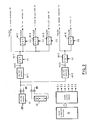
- Fig. 2 is a specific diagram showing a power supply system for the PC 100 according to the preferred embodiment of the present invention.
- the DC/DC converter 43 which is shown as a single block 43 in Fig. 1 is actually constituted by two blocks: a DC/DC converter 43-1 for supplying a voltage of 5 V and a DC/DC converter 43-2 for supplying a voltage of 3.3 V.
- the FET switch 44 in Fig. 1 is actually constituted by six FET switches 44-1 through 44-6.
- a power feed line V cc5 that extends from the DC/DC converter 43-1 is branched via the FET switch 44-1 to provide four sub-power feed lines V cc5G , v cc5A , v cc5B and v cc5P .
- the sub-power feed line v cc5G is connected to the power management processor 45, etc.; the v cc5A is connected to the main memory 13; the V cc5B is connected to the DASD (such as the HDD 22 and the FDD 24 ) ; and the V cc5P is connected to the LCD panel 18.
- the FET switches 44-3, 44-4, and 44-5 are inserted between the sub-power feed lines V cc5A , V cc5B , and V cc5P , and the supplied power destinations in order to halt the power supply.
- a power feed line v cc3 that extends from the DC/DC converter 43-2 is branched via the FET switch 44-2 to provide two sub-power feed lines V cc3A and v cc3B .
- the sub-power feed line v cc3A is connected to the memory controller 14 and the v cc3B is connected to the MPU 11, etc.
- the FET switch 44-6 is inserted between the sub-power feed line v cc3B and the supplied power destination in order to halt the power supply.
- the gate terminals of the six FET switches 44-1 through 44-6 are electrically connected to corresponding bit cells in the power control register 46.
- the power management processor 45 sets or resets the bit cells in the power control register 46 via the bus 12 to control the power supply for each sub-power feed line.
- the personal computer having the power supply system as shown in Fig. 2 can perform power management operations, such as an LCD-off, an HDD-off, and a suspend operation (for example, for the LCD-off operation, the FET switch 44-5 may be turned off, and for the suspend operation, the FET switches, other than the switches 44-1 and 44-3, may be turned off).
- power management operations such as an LCD-off, an HDD-off, and a suspend operation (for example, for the LCD-off operation, the FET switch 44-5 may be turned off, and for the suspend operation, the FET switches, other than the switches 44-1 and 44-3, may be turned off).
- the technique that relates to the power management processor 45 and the power control register 46 is also well known.
- a hardware block that is the equivalent of the power management processor 45 and the power control register 46 is described in, for example, the specifications for Japanese Patent Application No. Hei 04-54955 (Japanese Unexamined Patent Publication No. Hei 05-289784: our company reference No. JA9-92-004) and for Japanese Patent Application No. Hei 05-184186 (Japanese Unexamined Patent Publication No. Hei 07-84848: our company reference No.: JA9-93-020).
- the IBM ThinkPads 700C/750/755 that are sold by IBM Japan, Ltd., include hardware components that are the equivalent of the components 45 and 46.
- PC personal computer
- Fig. 3 is a schematic diagram illustrating the hierarchial software arrangement that can be employed by the PC 100 according to the preferred embodiment of the present invention.
- BIOS Basic Input/Output System
- the BIOS is a program group which includes a collection of basic operation commands for controlling the hardware components (such as the video controller 16, the keyboard 30, the HDD 22 and the FDD 23) in the system 100, and is coded and stored in the ROM 15.
- the BIOS also has functions for the handling of interrupt requests that are generated on the bus 12.
- An operating system is basic software for the total management of the hardware and the software of the system 100, and provides file management, memory management, task management and data input/output management, and a user interface (a system command and a system call) for handling a screen display and the manipulation of a mouse.
- OS/2 a trademark of IBM Corp.
- Windows a trademark of Microsoft Corp.
- the operating system in this embodiment includes, as one module, a PM (power management) program for executing a power management operation (see Section D).
- APs application programs
- Programs for word processing, databases, calculation for tables, and communication correspond to these application programs.
- the application programs are loaded as needed from the auxiliary storage device, such as the HDD 19 or the FDD 20, into the main memory 13 as desired by a user.
- Fig. 4 is a flowchart showing a routine (suspend routine) for entering suspend mode and a routine (resume routine) for recovering from the suspend mode and restarting a task.
- the power management processor 45 monitors the user input via the keyboard 30 or the mouse 31, and the operating state of the system 100.
- an internal suspend timer detects that a predetermined time (T SUS ) has elapsed since a last user input, or a last processing operation
- the power management processor 45 produces an interrupt request on the bus 12 (see Section A).
- the interrupt controller 26 detects this interrupt and reports it to the BIOS.
- the BIOS searches for the source that generated the interrupt request and detects that the interrupt originated at the power management processor 45. With the result as a trigger, the right to control the system 100 is transferred to the PM (power management) program, and the suspend routine starts.
- a check is performed to determine whether or not there is any I/O device activity (step S10).
- the check for the presence of I/O activity is again performed after a certain period (e.g., 10 msec) has elapsed.
- Program control goes on standby until no I/O device activity is detected.
- the PM program saves hardware context data in the main memory 13 (step S12). Then, VRAM original data are saved in the main memory 13 (step S14).
- Specific examples of hardware context data are the register values of individual chips, such as the MPU 11, the interrupt controller 26, the DMA controller 25 and the video controller 16, and the count values for the timers.
- the hardware context data and the VRAM data are required in order for a task to be resumed at the same point as when entering suspend mode.
- the PM program time-stamps real time (T 1 ) of the RTC 28 at this point into a predetermined area of the main memory 13 (step S16).
- the PM program requests the power management processor 45 to halt the power supply across specific power feed lines (power feed lines other than V cc5A ).
- the power management processor 45 alters the contents of the bit cells in the power control register 46. In this manner, the power supply to the electric circuits, except for the main memory 13, is halted and the suspend routine is thereafter terminated (step S18).
- the power management processor 45 is activated periodically and examines whether there is any input (or a resume request) entered via the keyboard 30 or the mouse 31.
- the power supply across the power feed lines is restarted (step S20).
- the MPU 11 executes the POST program in the ROM (step S22).
- the time interval ( ⁇ T) between the time- stamping at step S16 and S22 is calculated.
- the predetermined time T SUS of the suspend timer is changed. Two methods for altering the predetermined time T SUS are provided in this embodiment, and the following sections D-2 and D-3 should be referred to for detailed explanations of them.
- the PM program restores the VRAM original data and the hardware context data, which are saved in the main memory, to the original locations (steps S26 and S28).
- the system 100 After restoring the necessary data, the system 100 becomes almost the same state as just before entering the suspend mode, and can resume the task at the point where it was halted.
- the suspend timer In accordance with new predetermined time T SUS , which was altered at step S30, the suspend timer counts the elapsed time since a last user input or a last processing operation of the system 100. Each time when the system 100 enters the suspend mode and then resumes a task, the set time T SUS of the suspend timer is accordingly updated. It will be apparent that this dynamic update of the power management timer satisfies the requests for both power management and useability.
- Fig. 5 is a flowchart showing a first example method for altering the set time T SUS of the suspend timer (i.e., the example of the procedure at step S30 in Fig. 4).
- a check is performed to predetermine whether or not the time T 1 , which extends from a point when the system 100 enters the suspend mode to a point when the resume request is generated, is greater than a given reference value T th1 or not.
- the reference value T th1 may be an average time interval that the suspend mode continues, or may be a value that is obtained according to the empirical rule.
- the T SUS is compared with T max (step S42).
- the T max is the allowable maximum value for the time interval that is set for the suspend timer, and with a greater value than this, the power management effect of the system 100 would be adversely affected. Therefore, when the T SUS is equal to or greater than T max , the T SUS is not updated (step S44). When the T SUS is smaller than T max , the T SUS is incremented by a predetermined value ⁇ (step S46).
- the ⁇ T 1 is greater than the reference value T th1 , it means that neither user input nor processing operation of the system 100 has been detected for an extended period of time and no action affects the system 100. Since it is probable that the timing T SUS at which the system 100 enters the suspend mode is too long and the power management effect is thereby degraded, the value T SUS must be changed to a smaller value.
- the T SUS is compared with T min (step S48).
- the T min is the allowable minimum value for the time interval that is set for the suspend timer, and with a smaller value than this, the power management effect of the system 100 could not be maintained. Therefore, when the T SUS is equal to or smaller than T min , the T SUS is not updated (step S50). When the T SUS is greater than T min , the T SUS is decremented by a predetermined value ⁇ (step S52).
- the time predetermined as the suspend timer can be dynamically altered in accordance with the work habits of a user, and more optimal power management can be provided.
- increment value ⁇ and decrement value ⁇ may be values that are obtained according to the empirical rule. To obtain a greater effect, if a period required for entering the power management mode or a period required for returning to normal mode (i.e., the delay time for power management) is relatively long, these values ⁇ and ⁇ should be predetermined so that the period before the mode transition to the power management mode is as long as possible (i.e., the value ⁇ should be predetermined to a large value and the value ⁇ should be predetermined to a small value). If a period required for power management operation is relatively short, these values should be predetermined so that the mode transition to the power management mode tends to easily occur.
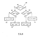
- Fig. 6 is a flowchart showing a second example method for altering the set time T SUS of the suspend timer (i.e., the example of the procedure at step S30 in Fig. 4).
- the set time T SUS is updated in consonance with time interval ⁇ T 2 (i.e., a period for one input job by a user) that extends from when the power supply starts to when the system 100 enters the suspend mode.
- ⁇ T 2 can be acquired as the difference between real time T 2,i , the point at which the system 100 is resumed at the ith time, and real time T 1,(i+1) , the point at which the system 100 enters the suspend mode at the (i+1)th time.
- a check is performed to determine whether or not the time T 2 , which extends from the point at which the system 100 resumes from the suspend mode to the point at which the system 100 enters the suspend mode again, is greater than a given reference value T th2 .
- the reference value T th2 is an average period of time that is required for a sequence of user input operation, and may be a value that is obtained according to the empirical rule.
- the time predetermined as the suspend timer is altered to a smaller value to obtain a greater power management effect while preventing the degrading of useability.
- the T SUS is compared with T min (step S62).
- the T min is allowable the minimum value for the time interval that is predetermined as the suspend timer (as described above).
- the T SUS is not updated (step S64).
- the T SUS is decremented by a predetermined value ⁇ (step S66).
- the time predetermined as the suspend timer is altered to a relatively greater value to prevent the degrading of useability.
- the T SUS is compared with T max (step S68).
- the T max is the allowable maximum value for the time interval that is predetermined as the suspend timer (as described above) .
- the T SUS is not updated (step S70).
- the T SUS is incremented by a predetermined value ⁇ (step S72).
- the increment value ⁇ and the decrement value ⁇ in section D-3 are acquired according to the empirical rule, as in section D-2. To obtain greater effects, these values are set according to a delay time caused by power management operation.
- the dynamic alteration of the power management timer can be applied for other power management operations, such as the LCD-off or the MPU speed slow-down operation.
- a PM program that executes the series of power management operations is included in the operating system.
- the present invention is not limited to this mode, and a software module that has an equivalent function as that of the PM program may be included in a different mode.
- a program may be coded and stored in the ROM 15.
- the present invention has been described in detail with reference to a specific embodiment. However, it should be obvious to one having ordinary skill in the art that various modifications or revisions of the embodiment are possible within the scope of the present invention.
- the present invention can be applied for a variety of electric/electronic systems that require power management: facsimile machines; various cordless devices, such as portable radio terminals, cordless telephones, electronic notebooks and video cameras; and word processors. That is, although the present invention has been disclosed by using an example, it should not be limited to that example. To understand the subject of the present invention, the claims should be referred to.
- an information processing system that has a power management function, such as suspend, and that learns the work habits of a user and dynamically alters a power management timer, and a control method therefor. It is therefore possible to maintain a balance between useability and power management, and to substantially increase the total performance of the system.
- the present invention is based on the observation of the common mentality that indicates that when the mode transition to the power management mode is against a user's will, the user wishes to recover the normal operation within a relatively short period of time after entering the power management mode. That is, according to an information processing system and a control method therefor, when user input or the system operation of the system 100 is resumed relatively early after entering the power management mode, it is assumed that a user probably feels that the time interval that is predetermined as a power management timer is so short that it provides inferior operability, and the time interval for the power management timer should be altered so that the next time it is longer.
- the mode transition to the power management mode is assumed to be appropriate for the needs of a user, or a system, and since the mode transition should be occurred rather earlier to increase the power management effect, the predetermined time interval for the power management timer is shortened the next time. As the power management timer is altered dynamically, the user operation is not unwillingly interrupted, and the power management effect can be increased.
Landscapes
- Engineering & Computer Science (AREA)
- Theoretical Computer Science (AREA)
- Physics & Mathematics (AREA)
- General Engineering & Computer Science (AREA)
- General Physics & Mathematics (AREA)
- Power Sources (AREA)
Applications Claiming Priority (2)
| Application Number | Priority Date | Filing Date | Title |
|---|---|---|---|
| JP155708/95 | 1995-06-22 | ||
| JP15570895A JP3213208B2 (ja) | 1995-06-22 | 1995-06-22 | 情報処理装置及びその制御方法 |
Publications (2)
| Publication Number | Publication Date |
|---|---|
| EP0750248A2 true EP0750248A2 (fr) | 1996-12-27 |
| EP0750248A3 EP0750248A3 (fr) | 1998-02-25 |
Family
ID=15611779
Family Applications (1)
| Application Number | Title | Priority Date | Filing Date |
|---|---|---|---|
| EP96304496A Withdrawn EP0750248A3 (fr) | 1995-06-22 | 1996-06-17 | Système de traitement d'information ayant une fonction d'économie d'énergie et méthode de contrÔle associée |
Country Status (4)
| Country | Link |
|---|---|
| US (1) | US5822597A (fr) |
| EP (1) | EP0750248A3 (fr) |
| JP (1) | JP3213208B2 (fr) |
| KR (1) | KR100241981B1 (fr) |
Cited By (4)
| Publication number | Priority date | Publication date | Assignee | Title |
|---|---|---|---|---|
| DE19703388C1 (de) * | 1997-01-30 | 1998-07-23 | Ibm | Verfahren und Vorrichtung zur Steuerung eines elektronischen Systems zum Zwecke der Energieeinsparung |
| WO2000026756A1 (fr) * | 1998-11-04 | 2000-05-11 | Phoenix Technologies Ltd. | Procede et appareil permettant d'obtenir une gestion intelligente de la consommation |
| WO2010103352A1 (fr) * | 2009-03-12 | 2010-09-16 | Sony Ericsson Mobile Communications Ab | Economie d'énergie adaptative |
| CN107506018A (zh) * | 2017-07-05 | 2017-12-22 | 深圳天珑无线科技有限公司 | 移动终端及其分级省电的方法、具有存储功能的装置 |
Families Citing this family (37)
| Publication number | Priority date | Publication date | Assignee | Title |
|---|---|---|---|---|
| KR100272163B1 (ko) * | 1997-12-30 | 2000-11-15 | 윤종용 | 대기용어레이전압발생기를갖는반도체메모리장치 |
| US6903835B1 (en) * | 1998-09-18 | 2005-06-07 | Canon Kabushiki Kaisha | Communication apparatus |
| US6038673A (en) * | 1998-11-03 | 2000-03-14 | Intel Corporation | Computer system with power management scheme for DRAM devices |
| US6539485B1 (en) * | 1999-05-24 | 2003-03-25 | Jonathan Liu | Intelligent sleep mode indicator |
| JP2001318742A (ja) * | 2000-05-08 | 2001-11-16 | Mitsubishi Electric Corp | コンピュータシステムおよびコンピュータ読み取り可能な記録媒体 |
| US20030074590A1 (en) * | 2001-10-12 | 2003-04-17 | Fogle Steven L. | Computer system with improved entry into powersave and lock modes and method of use therefor |
| US6816977B2 (en) * | 2001-12-03 | 2004-11-09 | Hewlett-Packard Development Company, L.P. | Power reduction in computing devices using micro-sleep intervals |
| US7055046B2 (en) * | 2002-06-28 | 2006-05-30 | Microsoft Corporation | Power management architecture for defining component power states under a global power state and applying a new component power state when a new component power state is greater than a registered power state floor |
| US7065659B2 (en) * | 2002-06-28 | 2006-06-20 | Microsoft Corporation | Power management architecture for defining component power states under a global power state and maintaining a power state floor for a specified component if a power state for the specified component under a new global power state is below the power state floor |
| US6885974B2 (en) * | 2003-01-31 | 2005-04-26 | Microsoft Corporation | Dynamic power control apparatus, systems and methods |
| JP4061492B2 (ja) | 2003-02-10 | 2008-03-19 | ソニー株式会社 | 情報処理装置および消費電力制御方法 |
| JP4295204B2 (ja) | 2004-12-16 | 2009-07-15 | インターナショナル・ビジネス・マシーンズ・コーポレーション | 磁気ディスク装置の電力制御方法、プログラム、電力制御装置、および電子情報機器 |
| US7386747B2 (en) * | 2005-05-10 | 2008-06-10 | Qualcomm Incorporated | Method and system for reducing power consumption of a programmable processor |
| US20060265617A1 (en) * | 2005-05-18 | 2006-11-23 | Priborsky Anthony L | Power management in a system having multiple power modes |
| JP4341594B2 (ja) * | 2005-06-30 | 2009-10-07 | セイコーエプソン株式会社 | 情報処理装置及び電力制御方法をコンピュータに実行させるためのプログラム |
| KR100726442B1 (ko) | 2006-01-02 | 2007-06-11 | 삼성전자주식회사 | 영상기기의 전원공급장치 및 전원공급방법 |
| US20090138133A1 (en) * | 2006-01-06 | 2009-05-28 | Wms Gaming Inc. | Power management in wagering game machines |
| JP2008022669A (ja) * | 2006-07-14 | 2008-01-31 | Nec Computertechno Ltd | 電源制御システムおよび電源制御方法 |
| US7743267B2 (en) * | 2006-11-08 | 2010-06-22 | Xerox Corporation | System and method for reducing power consumption in a device |
| US8487918B1 (en) * | 2008-03-07 | 2013-07-16 | Google Inc. | Context sensitive back light |
| JP2009239476A (ja) * | 2008-03-26 | 2009-10-15 | Nec Electronics Corp | 出力制御システム及びその制御方法 |
| KR101474315B1 (ko) * | 2009-04-14 | 2014-12-18 | 시게이트 테크놀로지 엘엘씨 | 스핀 업 오류를 방지하기 위한 하드디스크 드라이브 |
| JP5353508B2 (ja) * | 2009-07-15 | 2013-11-27 | 沖電気工業株式会社 | 電力制御装置及びプログラム |
| US9275690B2 (en) | 2012-05-30 | 2016-03-01 | Tahoe Rf Semiconductor, Inc. | Power management in an electronic system through reducing energy usage of a battery and/or controlling an output power of an amplifier thereof |
| KR101963589B1 (ko) * | 2012-06-18 | 2019-03-29 | 삼성전자주식회사 | 휴대단말기에서 RCS(Rich Communication Suite)의 Capability Discovery 수행 방법 및 장치 |
| US9043619B2 (en) * | 2012-06-19 | 2015-05-26 | Getac Technology Corporation | Method and apparatus for power management according to a situation mode |
| US9509351B2 (en) | 2012-07-27 | 2016-11-29 | Tahoe Rf Semiconductor, Inc. | Simultaneous accommodation of a low power signal and an interfering signal in a radio frequency (RF) receiver |
| US9837714B2 (en) | 2013-03-15 | 2017-12-05 | Integrated Device Technology, Inc. | Extending beamforming capability of a coupled voltage controlled oscillator (VCO) array during local oscillator (LO) signal generation through a circular configuration thereof |
| US9531070B2 (en) | 2013-03-15 | 2016-12-27 | Christopher T. Schiller | Extending beamforming capability of a coupled voltage controlled oscillator (VCO) array during local oscillator (LO) signal generation through accommodating differential coupling between VCOs thereof |
| US9716315B2 (en) | 2013-03-15 | 2017-07-25 | Gigpeak, Inc. | Automatic high-resolution adaptive beam-steering |
| US9780449B2 (en) | 2013-03-15 | 2017-10-03 | Integrated Device Technology, Inc. | Phase shift based improved reference input frequency signal injection into a coupled voltage controlled oscillator (VCO) array during local oscillator (LO) signal generation to reduce a phase-steering requirement during beamforming |
| US9722310B2 (en) | 2013-03-15 | 2017-08-01 | Gigpeak, Inc. | Extending beamforming capability of a coupled voltage controlled oscillator (VCO) array during local oscillator (LO) signal generation through frequency multiplication |
| US9184498B2 (en) | 2013-03-15 | 2015-11-10 | Gigoptix, Inc. | Extending beamforming capability of a coupled voltage controlled oscillator (VCO) array during local oscillator (LO) signal generation through fine control of a tunable frequency of a tank circuit of a VCO thereof |
| US9666942B2 (en) | 2013-03-15 | 2017-05-30 | Gigpeak, Inc. | Adaptive transmit array for beam-steering |
| KR102108839B1 (ko) | 2013-06-12 | 2020-05-29 | 삼성전자주식회사 | 불휘발성 메모리 장치를 포함하는 사용자 장치 및 그것의 데이터 쓰기 방법 |
| JP6410253B2 (ja) * | 2014-09-18 | 2018-10-24 | 東芝メモリ株式会社 | 電子機器 |
| US12554307B2 (en) * | 2022-12-30 | 2026-02-17 | Microsoft Technology Licensing, Llc | Presence detection power efficiency improvements |
Family Cites Families (6)
| Publication number | Priority date | Publication date | Assignee | Title |
|---|---|---|---|---|
| US5396635A (en) * | 1990-06-01 | 1995-03-07 | Vadem Corporation | Power conservation apparatus having multiple power reduction levels dependent upon the activity of the computer system |
| US5504907A (en) * | 1991-02-14 | 1996-04-02 | Dell Usa, L.P. | Power management system with adaptive control parameters for portable computer |
| WO1993007557A1 (fr) * | 1991-10-02 | 1993-04-15 | Kabushiki Kaisha Toshiba | Appareil electronique controlant automatiquement le courant electrique consomme par des composants en reaction a une duree de fonctionnement introduite par l'utilisateur |
| JPH05224787A (ja) * | 1992-02-12 | 1993-09-03 | Hitachi Ltd | 省電力制御方式 |
| US5416726A (en) * | 1992-10-06 | 1995-05-16 | Microsoft Corporation | Method and system for placing a computer in a reduced power state |
| US5617572A (en) * | 1995-01-31 | 1997-04-01 | Dell Usa, L.P. | System for reducing power consumption in computers |
-
1995
- 1995-06-22 JP JP15570895A patent/JP3213208B2/ja not_active Expired - Lifetime
-
1996
- 1996-05-23 US US08/652,201 patent/US5822597A/en not_active Expired - Lifetime
- 1996-06-17 KR KR1019960021753A patent/KR100241981B1/ko not_active Expired - Lifetime
- 1996-06-17 EP EP96304496A patent/EP0750248A3/fr not_active Withdrawn
Cited By (8)
| Publication number | Priority date | Publication date | Assignee | Title |
|---|---|---|---|---|
| DE19703388C1 (de) * | 1997-01-30 | 1998-07-23 | Ibm | Verfahren und Vorrichtung zur Steuerung eines elektronischen Systems zum Zwecke der Energieeinsparung |
| US6282664B1 (en) | 1997-01-30 | 2001-08-28 | International Business Machines Corporation | Method and apparatus for switching an electronic system between an operating mode and stand-by mode |
| WO2000026756A1 (fr) * | 1998-11-04 | 2000-05-11 | Phoenix Technologies Ltd. | Procede et appareil permettant d'obtenir une gestion intelligente de la consommation |
| US6347377B2 (en) | 1998-11-04 | 2002-02-12 | Phoenix Technologies Ltd. | Method and apparatus for providing intelligent power management |
| US6523123B2 (en) | 1998-11-04 | 2003-02-18 | Phoenix Technologies Ltd. | Method and apparatus for providing intelligent power management |
| WO2010103352A1 (fr) * | 2009-03-12 | 2010-09-16 | Sony Ericsson Mobile Communications Ab | Economie d'énergie adaptative |
| US8078896B2 (en) | 2009-03-12 | 2011-12-13 | Sony Ericsson Mobile Communications Ab | Adaptive power saving |
| CN107506018A (zh) * | 2017-07-05 | 2017-12-22 | 深圳天珑无线科技有限公司 | 移动终端及其分级省电的方法、具有存储功能的装置 |
Also Published As
| Publication number | Publication date |
|---|---|
| JPH096465A (ja) | 1997-01-10 |
| KR970002550A (ko) | 1997-01-28 |
| KR100241981B1 (ko) | 2000-02-01 |
| US5822597A (en) | 1998-10-13 |
| EP0750248A3 (fr) | 1998-02-25 |
| JP3213208B2 (ja) | 2001-10-02 |
Similar Documents
| Publication | Publication Date | Title |
|---|---|---|
| US5822597A (en) | Power management apparatus and method for an information processing system | |
| US5875345A (en) | Information processing system having dual power saving modes | |
| US5729061A (en) | Over discharge protection circuit for a rechargeable battery | |
| US6775784B1 (en) | Power supply control circuit and method for cutting off unnecessary power to system memory in the power-off state | |
| EP1141812B1 (fr) | Appareil et procede de commande automatique de vitesse d'unite centrale (uc) | |
| US5167024A (en) | Power management for a laptop computer with slow and sleep modes | |
| KR950004206B1 (ko) | 배터리로 작동되는 컴퓨터의 파워 관리 시스템 | |
| US6065122A (en) | Smart battery power management in a computer system | |
| US6266776B1 (en) | ACPI sleep control | |
| US9383813B2 (en) | Dynamic control of reduced voltage state of graphics controller component of memory controller | |
| US7117377B2 (en) | Computer apparatus, power supply control method and program for reducing the standby power requirement in a computer supporting a wake-up function | |
| JP3974510B2 (ja) | コンピュータ装置、電力管理方法、およびプログラム | |
| US6362980B1 (en) | Active filter for computer, filter module, power module and computer | |
| US20030159076A1 (en) | Keyboard controller providing power management for a portable computer system | |
| EP0770952B1 (fr) | Gestion de l'énergie dans un système de traitement d'information | |
| EP2843502A1 (fr) | Dispositif de traitement d'informations, procédé de traitement d'informations, et programme | |
| JP2003150281A (ja) | 電気機器、コンピュータ装置、および電力供給方法 | |
| GB2458805A (en) | Generating a power management policy for components of a system based on data from other components | |
| JPH04333119A (ja) | 情報処理装置 | |
| US5515539A (en) | Apparatus and method for reducing power consumption by peripheral devices after downloading a program therefrom | |
| US5978924A (en) | Computer system with an advanced power saving function and an operating method therefor | |
| US20050120256A1 (en) | Windows-driven power management for peripheral devices in a computer system | |
| US7257721B2 (en) | System and method of power management | |
| US6408397B1 (en) | Using RTC wake-up to enable recovery from power failures | |
| EP0560510A1 (fr) | Ordinateur opérant à piles et méthode de gestion d'alimentation de piles pour un tel ordinateur |
Legal Events
| Date | Code | Title | Description |
|---|---|---|---|
| PUAI | Public reference made under article 153(3) epc to a published international application that has entered the european phase |
Free format text: ORIGINAL CODE: 0009012 |
|
| AK | Designated contracting states |
Kind code of ref document: A2 Designated state(s): DE FR GB |
|
| 17P | Request for examination filed |
Effective date: 19970419 |
|
| PUAL | Search report despatched |
Free format text: ORIGINAL CODE: 0009013 |
|
| AK | Designated contracting states |
Kind code of ref document: A3 Designated state(s): DE FR GB |
|
| 17Q | First examination report despatched |
Effective date: 20021210 |
|
| STAA | Information on the status of an ep patent application or granted ep patent |
Free format text: STATUS: THE APPLICATION IS DEEMED TO BE WITHDRAWN |
|
| 18D | Application deemed to be withdrawn |
Effective date: 20030423 |