EP0750323A1 - Kontaktlose übertragungsanordnung und trägerstruktur zu deren anwendung - Google Patents
Kontaktlose übertragungsanordnung und trägerstruktur zu deren anwendung Download PDFInfo
- Publication number
- EP0750323A1 EP0750323A1 EP95910781A EP95910781A EP0750323A1 EP 0750323 A1 EP0750323 A1 EP 0750323A1 EP 95910781 A EP95910781 A EP 95910781A EP 95910781 A EP95910781 A EP 95910781A EP 0750323 A1 EP0750323 A1 EP 0750323A1
- Authority
- EP
- European Patent Office
- Prior art keywords
- electric power
- coupler
- fluid
- electric
- secondary side
- Prior art date
- Legal status (The legal status is an assumption and is not a legal conclusion. Google has not performed a legal analysis and makes no representation as to the accuracy of the status listed.)
- Granted
Links
Images

Classifications
-
- H—ELECTRICITY
- H01—ELECTRIC ELEMENTS
- H01F—MAGNETS; INDUCTANCES; TRANSFORMERS; SELECTION OF MATERIALS FOR THEIR MAGNETIC PROPERTIES
- H01F38/00—Adaptations of transformers or inductances for specific applications or functions
- H01F38/14—Inductive couplings
-
- Y—GENERAL TAGGING OF NEW TECHNOLOGICAL DEVELOPMENTS; GENERAL TAGGING OF CROSS-SECTIONAL TECHNOLOGIES SPANNING OVER SEVERAL SECTIONS OF THE IPC; TECHNICAL SUBJECTS COVERED BY FORMER USPC CROSS-REFERENCE ART COLLECTIONS [XRACs] AND DIGESTS
- Y10—TECHNICAL SUBJECTS COVERED BY FORMER USPC
- Y10T—TECHNICAL SUBJECTS COVERED BY FORMER US CLASSIFICATION
- Y10T29/00—Metal working
- Y10T29/49—Method of mechanical manufacture
- Y10T29/49002—Electrical device making
Definitions
- This invention relates to an FA connector for contactless transmission of electric power and signals which minimizes, in a machine tool working preparation system wherein a clamping or chucking operation of an object work is performed not manually but automatically using a fluid pressure such as a hydraulic pressure or a pneumatic pressure on a rotary member such as a circular table or a body which separately moves such as a work pallet for a machining center, the numbers of automatic couplings and external pipes for supply of fluid and allows fully automated remote control of solenoid valves.
- a fluid pressure such as a hydraulic pressure or a pneumatic pressure on a rotary member such as a circular table or a body which separately moves such as a work pallet for a machining center
- a connector for automatically connecting or disconnecting a hydraulic pressure or a pneumatic pressure has been recently developed, and this facilitates supply of power for clamping or chucking a work on a rotary member or an autonomous movable body.
- a connector for automatically connecting or disconnecting a hydraulic pressure or a pneumatic pressure
- a work clamp on a rotary table or a movable pallet in almost all cases includes a plurality of hydraulic (or pneumatic) actuators which operate independently of each other for one work and besides includes a plurality of works.
- actuators involved increases in this manner, also the number of automatic couplings and the number of pipes on the fixed side increase.
- An increase of the number of automatic couplings not only makes positioning for fitting difficult but also results in increase of the size of the coupling section and in deterioration of the reliability, and an increase in number of pipes gives rise to a problem in regard to an equipment arrangement.
- the number of fluid supply paths between the rotary member or movable body and the fixed section must be minimized by mounting a plurality of solenoid valves for controlling the individual actuators independently of each other on the rotary member or movable body.
- the point is how signals are communicated with power supplies for driving those solenoid valves.
- the conventional multiple contact type connector does not allow stable power supply, signal transmission and control for a long period of time because of presence of oil for generation of a hydraulic pressure, cutting oil, water, swarf and so forth.
- a contact type power feeder apparatus which is formed integrally with a manifold in which hydraulic pipes are arranged is disclosed in Japanese Patent Laid-open Application No. 290113/87. While this apparatus is constructed such that hydraulic pipes are joined together by a magnetic attracting force which is generated when power is supplied, it is dangerous in bad environment since it is of the contact type. Further, since a valve of a hydraulic apparatus must be operated on the fixed side (primary side), an autonomous operation of the movable side (secondary side) is impossible.
- Japanese Patent Laid-open Application No. 6993/94 proposed previously by the present applicant discloses details of a contactless feeder apparatus itself, it does not disclose an apparatus formed integrally with a coupling apparatus for fluid pipes.
- an FA connector for transmitting electric power, electric signals and fluid between a primary side and a secondary side, comprising:
- a rotary member for example, a multiple rotation circular table
- a movable body for example, a work pallet for a machining center
- electric power can be transmitted from the primary side, that is, the fixed side, by high frequency electromagnetic induction without electrode contacts and also signal communication is performed in a contactless way
- high frequency electric power is rectified, smoothed and stabilized to produce a solenoid valve driving power supply, a sensor power supply, and a CPU circuit control power supply.
- Transmission of on/off control signals for the solenoid valves is performed by serial communication via a high frequency split transformer of a small size which forms a magnetic path different from that of a split transformer for transmission of electric power, and a CPU mounted on the secondary side sequentially provides signals to solenoid driving elements to control the plurality of solenoid valves.
- contact information of the hydraulic and pneumatic apparatus mounted on the secondary side is transmitted by serial transmission by high frequency electromagnetic induction reversely from the secondary side to the primary side.
- analog instruction signals necessary for controlling servo valves and so forth and analog feedback signals such as detection values of the clamping forces or chucking forces are transmitted from the primary side to the secondary side or from the secondary side to the primary side by the same serial communication.
- the FA connector of the present invention even if clamping of a work by a fluid pressure (hydraulic pressure or pneumatic pressure) on a rotary table or a movable pallet is performed using a plurality of actuators or a plurality of works are to be clamped, control can be performed without increasing the number of automatic fluid couplings or the number of pipes on the fixed side, and as a result, the problems of increase of the size and deterioration of the reliability of the coupling section and increase of the size of a pipe equipment can be eliminated.
- a fluid pressure hydraulic pressure or pneumatic pressure
- the FA connector does not suffer from deterioration by bad environment at a working site of the machine tool (that is, presence of oil for generation of a hydraulic pressure, cutting oil, water, swarf or the like) and allows stable power supply and control for a long period of time.
- a working site of the machine tool that is, presence of oil for generation of a hydraulic pressure, cutting oil, water, swarf or the like
- the effect that strict alignment for fitting need not be performed is obtained. Consequently, the FA connector contributes very much to realization of full automation of the preparation process prior to the working process by a machine tool.
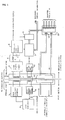
- FIG. 1 is a view showing a concept block diagram of the present invention
- FIG. 2 is a view showing an electromagnetic coupling
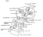
- FIG. 3 is a view showing an example of a concrete application of the present invention.
- FIG. 1 shows a construction of an FA connector according to the present invention.
- High frequency invertor 1 is provided on the primary side (fixed side) and generates a sine-wave or rectangular wave high frequency voltage higher than 10 kHz.
- the high frequency voltage is applied to the primary side of high frequency split transformer 2 as shown in FIG. 2.
- the secondary side of high frequency split transformer 2 is mounted on a rotary member or separate movable body side and is opposed to the primary side in a contactless way across a narrow gap left therebetween.
- a split transformer in the form of a pot is arranged concentrically with a rotary shaft in such a manner as shown in FIG. 2 so as to establish electromagnetic coupling irrespective of the angle of rotation.
- a high frequency voltage is generated in the secondary winding arranged close to the primary side (fixed side) with the narrow gap left therebetween, and this voltage is rectified and smoothed by diode bridge 3 and LC filter 4 mounted on the rotary member or movable body so that it is converted into a dc voltage. Then, the dc voltage is stabilized by stabilization circuit 5 and serves as power supply to solenoid valve control circuit 6, sensors not shown and parallel-serial conversion circuit 7.
- transmission of on/off signals for solenoid valves is performed by serial communication by high frequency electromagnetic induction by means of split transformer 10 of a small size which forms a magnetic path separately from high frequency split transformer 2 for power transmission after serial information from host controller 8 is modulated into a high frequency signal by high frequency modem 9.
- the modulated high frequency signal is received by the secondary side (rotary or movable side) and demodulated by high frequency modem 11 mounted on the secondary side, whereafter it is inputted in the form of serial data to parallel-serial conversion circuit 7.
- Parallel-serial conversion circuit 7 has also an operation processing function and sequentially provides signals to solenoid valve control circuit 6 to control a plurality of solenoid valves 13 of fluid branching section 12.
- pressure or contact information 14 of a plurality of hydraulic or pneumatic sensor apparatus mounted on the secondary side is fetched conversely to parallel-serial conversion circuit 7 and is fed back by serial transmission from the secondary side to the primary side similarly by high frequency electromagnetic induction.
- analog instruction signals necessary for controlling hydraulic and/or pneumatic servo valves and analog feedback signals such as detection values of clamping forces and chucking forces are transmitted from the primary side to the secondary side or from the secondary side to the primary side by the same serial communication.
- FIG. 3 shows an example wherein the present invention is applied to a pallet.
- Pallet 31 has a built-in secondary side circuit of an FA connector of the present invention built therein and has work clampers 33 for fixing work 32 using a hydraulic pressure of the secondary side circuit.
- a primary side circuit of the FA connector of the present invention is attached to an end of each of fitting cylinders 34 such that electromagnetic coupler 37 and fluid couplers 38 and 39 are coupled between the primary side and the secondary side by fitting guide pins 35 into guide holes 36.
- the electromagnetic coupler feeds power in a contactless way while it keeps an electrically isolated condition. This eliminates the possibility that an electric spark may be produced.
- Electromagnetic coupler 37 includes a coaxial arrangement of split transformers 2 and 10 for electric power and electric signals, respectively.
- each of work clampers 33 which fix works using fluid pressures is hydraulically controlled, there is no problem in using a hydraulic pressure to fix a work because a pressure keeping function can be achieved readily using a check valve or a like element, but where each of work clampers 33 is pneumatically controlled, consideration is needed because, different from a hydraulic pressure, it is difficult to keep a pressure by pneumatic control.
- a CPU is mounted on the secondary side (on the rotary member or separate movable body) and serial communication is performed, then the number of couplings for signals can be reduced remarkably and the number of informations such as seating of a mounted and fixed work and feedback of sensor signals for confirmation of clamping forces can be increased.
- the CPU is provided on the movable body, also communication of IDs of a work and the pallet and working information can be performed by a backing up memory.
- the connector according to the present invention is effective not only for machine tools, but also for control of a plurality of hydraulic or pneumatic actuators attached to an end of a robot arm. Particularly where a plurality of air supply and discharge paths are involved like a pneumatically driven tool exchange of the turret type, a connector of the rotary type is effective.
- the present invention is available for a work pallet used for a machine tool or a like machine and peripheral apparatus of the work pallet.
Landscapes
- Engineering & Computer Science (AREA)
- Power Engineering (AREA)
- Feeding Of Workpieces (AREA)
- Jigs For Machine Tools (AREA)
- Quick-Acting Or Multi-Walled Pipe Joints (AREA)
- Dc-Dc Converters (AREA)
- Machine Tool Units (AREA)
- Details Of Connecting Devices For Male And Female Coupling (AREA)
- Fittings On The Vehicle Exterior For Carrying Loads, And Devices For Holding Or Mounting Articles (AREA)
Applications Claiming Priority (3)
| Application Number | Priority Date | Filing Date | Title |
|---|---|---|---|
| JP67749/94 | 1994-03-11 | ||
| JP06067749A JP3116715B2 (ja) | 1994-03-11 | 1994-03-11 | Faコネクタおよびそれを用いたワークパレット |
| PCT/JP1995/000392 WO1995024722A1 (en) | 1994-03-11 | 1995-03-09 | Fa connector and work pallet using it |
Publications (3)
| Publication Number | Publication Date |
|---|---|
| EP0750323A1 true EP0750323A1 (de) | 1996-12-27 |
| EP0750323A4 EP0750323A4 (de) | 1997-06-04 |
| EP0750323B1 EP0750323B1 (de) | 1999-01-13 |
Family
ID=13353910
Family Applications (1)
| Application Number | Title | Priority Date | Filing Date |
|---|---|---|---|
| EP95910781A Expired - Lifetime EP0750323B1 (de) | 1994-03-11 | 1995-03-09 | Kontaktlose übertragungsanordnung und trägerstruktur zu deren anwendung |
Country Status (6)
| Country | Link |
|---|---|
| US (1) | US5747894A (de) |
| EP (1) | EP0750323B1 (de) |
| JP (1) | JP3116715B2 (de) |
| KR (1) | KR100328010B1 (de) |
| DE (1) | DE69507288T2 (de) |
| WO (1) | WO1995024722A1 (de) |
Cited By (3)
| Publication number | Priority date | Publication date | Assignee | Title |
|---|---|---|---|---|
| EP0867899A3 (de) * | 1997-03-26 | 1999-07-21 | Matsushita Electric Works, Ltd. | Kontaktlose Energieübertragungseinrichtung |
| EP1591670A3 (de) * | 2004-04-28 | 2006-01-25 | Bosch Rexroth AG | Pneumatische Baugruppe mit drahtloser Energieversorgung |
| CN102611207A (zh) * | 2012-03-14 | 2012-07-25 | 邹磊 | 射频供能便携式设备的电源管理模块 |
Families Citing this family (31)
| Publication number | Priority date | Publication date | Assignee | Title |
|---|---|---|---|---|
| JP3456093B2 (ja) * | 1996-06-25 | 2003-10-14 | 松下電工株式会社 | 非接触電力伝達装置 |
| US6430069B1 (en) * | 1999-05-14 | 2002-08-06 | Intel Corporation | Contactless connectors for use in a high frequency alternating current power distribution system |
| US7612528B2 (en) | 1999-06-21 | 2009-11-03 | Access Business Group International Llc | Vehicle interface |
| ES2171097B1 (es) * | 1999-06-21 | 2003-11-01 | Univ Sevilla | Sensor electronico para la medida de la posicion angular de un objeto luminiscente. |
| US6825620B2 (en) * | 1999-06-21 | 2004-11-30 | Access Business Group International Llc | Inductively coupled ballast circuit |
| US7126450B2 (en) * | 1999-06-21 | 2006-10-24 | Access Business Group International Llc | Inductively powered apparatus |
| US7385357B2 (en) | 1999-06-21 | 2008-06-10 | Access Business Group International Llc | Inductively coupled ballast circuit |
| DE10115535A1 (de) * | 2001-03-28 | 2002-10-10 | Walter Holzer | DC/AC WANDLER mit kontaktloser, induktiver Energieübertragung |
| JP4811624B2 (ja) * | 2001-07-31 | 2011-11-09 | ソニー株式会社 | 流体コネクタおよび流体コネクタ装置 |
| US6733411B1 (en) | 2002-01-31 | 2004-05-11 | Dana Corporation | Electronically controlled hydraulic actuator for limited slip differential assembly |
| DE10203765B4 (de) * | 2002-01-31 | 2006-11-30 | Rexroth Mecman Gmbh | Elektromagnetisches Mehrwegeventil mit einer kontaktfreien elektrischen Leistungsübertragung |
| US7462951B1 (en) | 2004-08-11 | 2008-12-09 | Access Business Group International Llc | Portable inductive power station |
| US7408324B2 (en) * | 2004-10-27 | 2008-08-05 | Access Business Group International Llc | Implement rack and system for energizing implements |
| US20080181316A1 (en) * | 2007-01-25 | 2008-07-31 | Philip John Crawley | Partitioned Signal and Power Transfer Across an Isolation Barrier |
| JP4924122B2 (ja) * | 2007-03-16 | 2012-04-25 | 富士ゼロックス株式会社 | 非接触伝送装置 |
| US8215004B2 (en) | 2007-07-30 | 2012-07-10 | Sintokogio, Ltd. | Fabrication line |
| GB2464945B (en) * | 2008-10-29 | 2013-07-10 | Wfs Technologies Ltd | Electrical connector system |
| US20120007442A1 (en) * | 2009-02-06 | 2012-01-12 | Mark Rhodes | Rotary data and power transfer system |
| GB2483374A (en) * | 2010-09-03 | 2012-03-07 | Wfs Technologies Ltd | Transferring power between a fixed unit and a rotating unit using a rotary transformer, and also transferring data |
| JP2015500746A (ja) * | 2011-12-09 | 2015-01-08 | ダイムラー・アクチェンゲゼルシャフトDaimler AG | 製造プラントの運転方法 |
| JP5884698B2 (ja) * | 2012-09-28 | 2016-03-15 | トヨタ自動車株式会社 | 非接触受電装置 |
| CN102921839A (zh) * | 2012-11-19 | 2013-02-13 | 无锡九条龙汽车设备有限公司 | 一种三极管模切定位板 |
| EP3081314A1 (de) * | 2015-04-16 | 2016-10-19 | Eftec Europe Holding AG | Vorrichtung zum auftragen von fluiden |
| WO2017151433A1 (en) * | 2016-02-29 | 2017-09-08 | Moldman Systems Llc | Mechanisms and methods for mixing and/or dispensing multi-part materials |
| WO2017154174A1 (ja) * | 2016-03-10 | 2017-09-14 | 株式会社日立製作所 | 無線給電システム、給電側装置、および受電側装置 |
| JP6444940B2 (ja) * | 2016-05-17 | 2018-12-26 | ファナック株式会社 | 被加工物保持システム |
| DE102017131101B4 (de) * | 2017-12-22 | 2023-04-20 | Bürkert Werke GmbH & Co. KG | Ventilbaugruppe |
| JP7344658B2 (ja) | 2019-03-18 | 2023-09-14 | コマツNtc株式会社 | ワーク支持装置 |
| US11443889B2 (en) | 2019-06-24 | 2022-09-13 | Texas Instruments Incorporated | Data and power isolation barrier |
| EP4585361B1 (de) * | 2021-09-13 | 2026-05-13 | SMW-AUTOBLOK Spannsysteme GmbH | Spannvorrichtung |
| WO2025226211A1 (en) * | 2024-04-26 | 2025-10-30 | Teinspace Pte. Ltd. | An apparatus for fluid delivery |
Family Cites Families (10)
| Publication number | Priority date | Publication date | Assignee | Title |
|---|---|---|---|---|
| JPS4932578B1 (de) * | 1970-02-23 | 1974-08-31 | ||
| US4837556A (en) * | 1985-04-15 | 1989-06-06 | Kabushiki Kaisha Nihon Denzai Kogyo Kenkyusho | Signal transmission device |
| JPS62120945A (ja) * | 1985-11-20 | 1987-06-02 | Tokyo Keiki Co Ltd | 工具ホルダ |
| US4855982A (en) * | 1987-05-18 | 1989-08-08 | Eastman Kodak Company | Lens position-sensing apparatus for optical recording system |
| FR2640415B1 (fr) * | 1988-12-13 | 1994-02-25 | Schlumberger Prospection Electr | Connecteur a accouplement inductif destine a equiper les installations de surface d'un puits |
| GB9011970D0 (en) * | 1990-05-29 | 1990-07-18 | Leigh Stewart Prod | Electrical control system for,for example,an air spa bath |
| JPH05111845A (ja) * | 1991-06-19 | 1993-05-07 | Hitachi Seiki Co Ltd | 工作機械の電気、油空圧供給装置 |
| JP2648542B2 (ja) * | 1992-03-13 | 1997-09-03 | 株式会社安川電機 | 油圧発生装置および該装置を備えた作業機械 |
| US5229652A (en) * | 1992-04-20 | 1993-07-20 | Hough Wayne E | Non-contact data and power connector for computer based modules |
| JP2589836Y2 (ja) * | 1993-05-28 | 1999-02-03 | 株式会社森精機製作所 | 工作機械のパレット給電構造 |
-
1994
- 1994-03-11 JP JP06067749A patent/JP3116715B2/ja not_active Expired - Fee Related
-
1995
- 1995-03-09 KR KR1019960705010A patent/KR100328010B1/ko not_active Expired - Fee Related
- 1995-03-09 EP EP95910781A patent/EP0750323B1/de not_active Expired - Lifetime
- 1995-03-09 US US08/704,543 patent/US5747894A/en not_active Expired - Fee Related
- 1995-03-09 WO PCT/JP1995/000392 patent/WO1995024722A1/ja not_active Ceased
- 1995-03-09 DE DE69507288T patent/DE69507288T2/de not_active Expired - Fee Related
Cited By (3)
| Publication number | Priority date | Publication date | Assignee | Title |
|---|---|---|---|---|
| EP0867899A3 (de) * | 1997-03-26 | 1999-07-21 | Matsushita Electric Works, Ltd. | Kontaktlose Energieübertragungseinrichtung |
| EP1591670A3 (de) * | 2004-04-28 | 2006-01-25 | Bosch Rexroth AG | Pneumatische Baugruppe mit drahtloser Energieversorgung |
| CN102611207A (zh) * | 2012-03-14 | 2012-07-25 | 邹磊 | 射频供能便携式设备的电源管理模块 |
Also Published As
| Publication number | Publication date |
|---|---|
| JPH07249531A (ja) | 1995-09-26 |
| JP3116715B2 (ja) | 2000-12-11 |
| KR100328010B1 (ko) | 2002-04-17 |
| WO1995024722A1 (en) | 1995-09-14 |
| EP0750323B1 (de) | 1999-01-13 |
| DE69507288D1 (de) | 1999-02-25 |
| EP0750323A4 (de) | 1997-06-04 |
| DE69507288T2 (de) | 1999-05-27 |
| US5747894A (en) | 1998-05-05 |
| KR970701913A (ko) | 1997-04-12 |
Similar Documents
| Publication | Publication Date | Title |
|---|---|---|
| US5747894A (en) | Factory automation connector and work pallet | |
| KR100309240B1 (ko) | 무접촉전력전송장치,무접촉신호전송장치및이들을사용한분리형기계장치와그제어방법 | |
| US5887430A (en) | Hydraulic source and hydraulic machine | |
| US4676142A (en) | Adapter with modular components for a robot end-of-arm interchangeable tooling system | |
| CN105312729B (zh) | 焊接系统以及焊接系统的通信方法 | |
| EP0722811A1 (de) | Robot ohne kabelverbindung | |
| US12030146B2 (en) | Transmission arrangement and method for transmitting energy and signals between a control unit of a machine tool and electronic components | |
| WO1997026118A1 (en) | Integrated stud welding robotic tool changing system | |
| CN111844109A (zh) | 一种工业机器人智能手腕装备系统及其操作方法 | |
| US6914790B2 (en) | Motor driving controller | |
| CN206825016U (zh) | 被加工物保持系统 | |
| CN106736193A (zh) | 一种管接头全自动焊接定位设备 | |
| JPH066993A (ja) | 電動機の無接触給電制御方法、該方法による分離型制御電動機、及び該分離型制御電動機を用いた機械装置 | |
| JPH05253776A (ja) | 油圧発生装置および該装置を備えた作業機械 | |
| WO2010111159A2 (en) | Welding apparatus and methods | |
| US20020118098A1 (en) | System for a machine or plant having a large number of sensors and/or actuators | |
| JPH0730489A (ja) | 多回転テーブル | |
| JPH0865926A (ja) | 自律式空圧発生装置 | |
| CN218776614U (zh) | 一种机器人取件快速更换装置 | |
| CN117062688A (zh) | 用于加工工件的系统、机床、支撑装置和工件支撑件 | |
| CN213562670U (zh) | 在机器人与端拾器之间的无线感应系统及机器人总成 | |
| CN220841334U (zh) | 一种注塑机机械手电气调试治具及装置 | |
| KR100299702B1 (ko) | 다회전형 액튜에이터 제어장치 | |
| CN116587269B (zh) | 快换式氩气管自动插拔设备及方法 | |
| CN121535574A (zh) | 基于多源快插技术的机床自动化加工托盘及交互方法 |
Legal Events
| Date | Code | Title | Description |
|---|---|---|---|
| PUAI | Public reference made under article 153(3) epc to a published international application that has entered the european phase |
Free format text: ORIGINAL CODE: 0009012 |
|
| 17P | Request for examination filed |
Effective date: 19961009 |
|
| AK | Designated contracting states |
Kind code of ref document: A1 Designated state(s): DE GB SE |
|
| A4 | Supplementary search report drawn up and despatched | ||
| AK | Designated contracting states |
Kind code of ref document: A4 Designated state(s): DE GB SE |
|
| 17Q | First examination report despatched |
Effective date: 19970619 |
|
| GRAG | Despatch of communication of intention to grant |
Free format text: ORIGINAL CODE: EPIDOS AGRA |
|
| GRAG | Despatch of communication of intention to grant |
Free format text: ORIGINAL CODE: EPIDOS AGRA |
|
| GRAH | Despatch of communication of intention to grant a patent |
Free format text: ORIGINAL CODE: EPIDOS IGRA |
|
| GRAH | Despatch of communication of intention to grant a patent |
Free format text: ORIGINAL CODE: EPIDOS IGRA |
|
| GRAA | (expected) grant |
Free format text: ORIGINAL CODE: 0009210 |
|
| AK | Designated contracting states |
Kind code of ref document: B1 Designated state(s): DE GB SE |
|
| PG25 | Lapsed in a contracting state [announced via postgrant information from national office to epo] |
Ref country code: SE Free format text: THE PATENT HAS BEEN ANNULLED BY A DECISION OF A NATIONAL AUTHORITY Effective date: 19990113 |
|
| REF | Corresponds to: |
Ref document number: 69507288 Country of ref document: DE Date of ref document: 19990225 |
|
| PLBE | No opposition filed within time limit |
Free format text: ORIGINAL CODE: 0009261 |
|
| STAA | Information on the status of an ep patent application or granted ep patent |
Free format text: STATUS: NO OPPOSITION FILED WITHIN TIME LIMIT |
|
| 26N | No opposition filed | ||
| PGFP | Annual fee paid to national office [announced via postgrant information from national office to epo] |
Ref country code: GB Payment date: 20010307 Year of fee payment: 7 |
|
| REG | Reference to a national code |
Ref country code: GB Ref legal event code: IF02 |
|
| PG25 | Lapsed in a contracting state [announced via postgrant information from national office to epo] |
Ref country code: GB Free format text: LAPSE BECAUSE OF NON-PAYMENT OF DUE FEES Effective date: 20020309 |
|
| PGFP | Annual fee paid to national office [announced via postgrant information from national office to epo] |
Ref country code: DE Payment date: 20020327 Year of fee payment: 8 |
|
| GBPC | Gb: european patent ceased through non-payment of renewal fee |
Effective date: 20020309 |
|
| PG25 | Lapsed in a contracting state [announced via postgrant information from national office to epo] |
Ref country code: DE Free format text: LAPSE BECAUSE OF NON-PAYMENT OF DUE FEES Effective date: 20031001 |