EP0750376B1 - Presse-étoupe de terminaison pour câble électrique - Google Patents
Presse-étoupe de terminaison pour câble électrique Download PDFInfo
- Publication number
- EP0750376B1 EP0750376B1 EP96304585A EP96304585A EP0750376B1 EP 0750376 B1 EP0750376 B1 EP 0750376B1 EP 96304585 A EP96304585 A EP 96304585A EP 96304585 A EP96304585 A EP 96304585A EP 0750376 B1 EP0750376 B1 EP 0750376B1
- Authority
- EP
- European Patent Office
- Prior art keywords
- continuity member
- gland
- cable
- bridge portions
- sheathing
- Prior art date
- Legal status (The legal status is an assumption and is not a legal conclusion. Google has not performed a legal analysis and makes no representation as to the accuracy of the status listed.)
- Expired - Lifetime
Links
- 210000004907 gland Anatomy 0.000 title claims description 69
- 229910052751 metal Inorganic materials 0.000 claims description 54
- 239000002184 metal Substances 0.000 claims description 54
- 238000005253 cladding Methods 0.000 claims description 35
- 239000004020 conductor Substances 0.000 claims description 9
- 238000000034 method Methods 0.000 claims description 7
- 230000006835 compression Effects 0.000 claims description 6
- 238000007906 compression Methods 0.000 claims description 6
- RYGMFSIKBFXOCR-UHFFFAOYSA-N Copper Chemical compound [Cu] RYGMFSIKBFXOCR-UHFFFAOYSA-N 0.000 claims description 5
- 229910052802 copper Inorganic materials 0.000 claims description 5
- 239000010949 copper Substances 0.000 claims description 5
- 238000006073 displacement reaction Methods 0.000 claims description 4
- 230000002093 peripheral effect Effects 0.000 claims description 4
- 229910000831 Steel Inorganic materials 0.000 claims description 2
- 239000004411 aluminium Substances 0.000 claims description 2
- 229910052782 aluminium Inorganic materials 0.000 claims description 2
- XAGFODPZIPBFFR-UHFFFAOYSA-N aluminium Chemical compound [Al] XAGFODPZIPBFFR-UHFFFAOYSA-N 0.000 claims description 2
- 239000010959 steel Substances 0.000 claims description 2
- 238000005096 rolling process Methods 0.000 claims 2
- 229910000881 Cu alloy Inorganic materials 0.000 claims 1
- 230000004888 barrier function Effects 0.000 description 22
- 150000001875 compounds Chemical class 0.000 description 16
- 239000000463 material Substances 0.000 description 4
- 238000010276 construction Methods 0.000 description 3
- 125000006850 spacer group Chemical group 0.000 description 3
- PXHVJJICTQNCMI-UHFFFAOYSA-N Nickel Chemical compound [Ni] PXHVJJICTQNCMI-UHFFFAOYSA-N 0.000 description 2
- 239000000956 alloy Substances 0.000 description 2
- 229910045601 alloy Inorganic materials 0.000 description 2
- 238000011065 in-situ storage Methods 0.000 description 2
- BGAJNPLDJJBRHK-UHFFFAOYSA-N 3-[2-[5-(3-chloro-4-propan-2-yloxyphenyl)-1,3,4-thiadiazol-2-yl]-3-methyl-6,7-dihydro-4h-pyrazolo[4,3-c]pyridin-5-yl]propanoic acid Chemical compound C1=C(Cl)C(OC(C)C)=CC=C1C1=NN=C(N2C(=C3CN(CCC(O)=O)CCC3=N2)C)S1 BGAJNPLDJJBRHK-UHFFFAOYSA-N 0.000 description 1
- 239000004593 Epoxy Substances 0.000 description 1
- HCHKCACWOHOZIP-UHFFFAOYSA-N Zinc Chemical compound [Zn] HCHKCACWOHOZIP-UHFFFAOYSA-N 0.000 description 1
- 230000004323 axial length Effects 0.000 description 1
- 230000015572 biosynthetic process Effects 0.000 description 1
- 238000001816 cooling Methods 0.000 description 1
- 230000018109 developmental process Effects 0.000 description 1
- 239000000945 filler Substances 0.000 description 1
- 239000007789 gas Substances 0.000 description 1
- 231100001261 hazardous Toxicity 0.000 description 1
- 239000012943 hotmelt Substances 0.000 description 1
- 239000007788 liquid Substances 0.000 description 1
- 239000007937 lozenge Substances 0.000 description 1
- 239000000203 mixture Substances 0.000 description 1
- 229910052759 nickel Inorganic materials 0.000 description 1
- 238000012856 packing Methods 0.000 description 1
- 238000002360 preparation method Methods 0.000 description 1
- 230000001681 protective effect Effects 0.000 description 1
- 239000012858 resilient material Substances 0.000 description 1
- 239000011347 resin Substances 0.000 description 1
- 229920005989 resin Polymers 0.000 description 1
- 239000007787 solid Substances 0.000 description 1
- 229910052725 zinc Inorganic materials 0.000 description 1
- 239000011701 zinc Substances 0.000 description 1
Images


Classifications
-
- H—ELECTRICITY
- H02—GENERATION; CONVERSION OR DISTRIBUTION OF ELECTRIC POWER
- H02G—INSTALLATION OF ELECTRIC CABLES OR LINES, OR OF COMBINED OPTICAL AND ELECTRIC CABLES OR LINES
- H02G15/00—Cable fittings
- H02G15/02—Cable terminations
- H02G15/04—Cable-end sealings
-
- H—ELECTRICITY
- H01—ELECTRIC ELEMENTS
- H01R—ELECTRICALLY-CONDUCTIVE CONNECTIONS; STRUCTURAL ASSOCIATIONS OF A PLURALITY OF MUTUALLY-INSULATED ELECTRICAL CONNECTING ELEMENTS; COUPLING DEVICES; CURRENT COLLECTORS
- H01R4/00—Electrically-conductive connections between two or more conductive members in direct contact, i.e. touching one another; Means for effecting or maintaining such contact; Electrically-conductive connections having two or more spaced connecting locations for conductors and using contact members penetrating insulation
- H01R4/58—Electrically-conductive connections between two or more conductive members in direct contact, i.e. touching one another; Means for effecting or maintaining such contact; Electrically-conductive connections having two or more spaced connecting locations for conductors and using contact members penetrating insulation characterised by the form or material of the contacting members
- H01R4/64—Connections between or with conductive parts having primarily a non-electric function, e.g. frame, casing, rail
- H01R4/646—Connections between or with conductive parts having primarily a non-electric function, e.g. frame, casing, rail for cables or flexible cylindrical bodies
Definitions
- This invention relates to an electric cable termination gland and to a method of assembling same.
- the invention has particular application to glands for electric cables that have metallic sheathing or armour metal cladding and that require to be assembled and fitted to ensure electrical continuity for earthing (grounding) between the sheathing or cladding and the electrical equipment at which the cable terminates.
- cables are made to various sizes and types, and there are different forms and configurations of the metal claddings and/or armour sheathings that have to be accommodated in the assembly and use of cable glands.
- metal claddings or armour sheathings of various types including continuous, convoluted, corrugated, interlocking, woven or helically wound.
- these types of cables are referred to as metal clad, but it should be appreciated that such cables also commonly have an outer protective covering or jacket to protect the cable, and such jackets or covering may be of any suitable material.
- the cables are made to different sizes with different numbers of conductor cores, and termination glands have to be made to a range of different sizes. In addition, there are different types of such cable glands.
- Some cable glands used for termination of electric cables are of the type including a barrier which prevents the ingress of liquid, gas or solids into the interstices of the cable and the space between the cable cores when the cable sheathing has been removed to allow connection of the cable conductors to some electrical equipment.
- the barrier is commonly provided by a compound which is used to fill the interstices and space between the cable cores within the gland assembly.
- the filler compound can be a hot melt composition which sets on cooling or it can be a an epoxy or like resin that is mixed or used when having a "putty" consistency and which hardens later when the gland is assembled.
- the gland may be designed especially for such use of the compound to provide the barrier, and we have developed such glands previously, such as described in our UK Patents Nos.1528347 and 1528348.
- FR-A-2 339 977 discloses an electric cable termination gland having a first component, a middle component to engage with the first component and a third component to engage with the middle component.
- a continuity member is located inside the middle component and engages internal abutments associated with the first component and the middle component.
- the continuity member comprises a series of axially extending contact fingers connected at one end to a ring and separated by apertures. The free ends of the fingers are displaced radially inwards towards exposed metal cladding of a cable extending through the gland when the middle component is tightened on the first component and, on engagement with the metal cladding, provide at least one electrical continuity contact.
- FR-A-2 630 577 discloses an electric cable termination gland having a first component and a second component to engage with the first component.
- a continuity member is located within the gland between internal abutments associated with the first and second components.
- the continuity member comprises a split ring arranged to contract radially inwards towards exposed metal cladding of a cable extending through the gland when the first and second components are tightened and, on engagement with the metal cladding, provides an electrical continuity contact.
- Another objects of this invention are to provide a method of assembling an electric termination gland to ensure electrical continuity as well as providing an improved electric termination gland which is of simple construction and easy to use in hazardous or difficult site locations.
- an electric cable termination gland comprising an entry component for connection to electrical equipment, a middle nut to engage with the entry component and a tail nut to engage with the middle nut, a continuity member located inside the middle nut and engaging an abutment therein, and the entry component having an end abutment received inside that end of the middle nut remote from the tail nut with the continuity member also engaging said end abutment, the continuity member having a middle region of reduced strength provided by a series discrete bridge portions separated by spaced apart apertures, the arrangement being such that on tightening the middle nut on the entry component when an electric cable extends through the gland with a metal cladding or sheathing being exposed within the middle nut, the continuity member is subject to axial pressure and the region of reduced strength folds inwardly whereby the bridge portions are displaced towards the metal cladding or sheathing and, on engagement with the metal cladding or sheathing, provide at least one electrical continuity contact.
- the gland has the special arrangement with the continuity member which is seated within the middle nut, and on tightening the assembly of the middle nut onto the entry component, the continuity member reacts to the axial pressure so that contact with the metal cladding is produced by the displacement of the bridge portions.
- the continuity member is made of a high conductive metal such as copper or an alloy thereof.
- the metal may also be steel or aluminium.
- the metal may be plated or coated such as with zinc, nickel or copper.
- the continuity member is formed from a strip which is rolled to form a sleeve or ring-like continuity member.
- the continuity member is of high electrical conductivity, and can be made in a simple manner to fit a wide range of gland sizes.
- the apertures may be of different shapes and configurations and designed so that the discrete bridge portions are arranged to provide a plurality of spaced apart contacts to engage the metal cladding of the cable in use.
- the strip is provided with a central creasing about which the bridge portions are designed to fold when the axial force is applied to the opposed ends of the member.
- the apertures may be elongate so as to extend between opposed ends of the continuity member.
- Each end of the continuity member may be strengthened by a peripheral upstand or rolled edge.
- This invention is also directed to the continuity member for use in an electric cable termination gland for a cable having an exposed metal sheathing or cladding, the contacts member comprising a hollow sleeve through which a cable extending through a gland in which the continuity member is located can pass the continuity member having a zone of reduced strength formed by spaced apart apertures that extend generally in the axial direction of the hollow sleeve to create a series of discrete bridge portions providing a plurality of spaced apart contacts for engagement with the exposed metal cladding or sheathing and the bridge portions are formed with a crease to cause the bridge portions to fold inwardly to contact the exposed metal cladding or sheathing in response to the continuity member being subjected to axial compression.
- the cable gland may be of the barrier type with a compound pot received within the entry component and a rear pot also located in the entry component with the cores extending through the entry component with the barrier compound being received within the compound pot and rear pot.
- the cable gland may be of the non-barrier type with the entry component locating a stop washer and spacer sleeve with which the exposed end of the metal cladding of the cable are engaged.
- a continuity member for an electric cable termination gland comprising a hollow sleeve having a zone of reduced strength formed by spaced apart apertures that extend generally in the axial direction of the hollow sleeve to create a series of discrete bridge portions providing a plurality of spaced apart contacts for engagement with exposed metal cladding or sheathing of a cable extending through a gland in which the continuity member is located, and the bridge portions are formed with a crease to cause the bridge portions to fold inwardly to contact the exposed metal cladding or sheathing(in response to the continuity member (6;106) being subjected to axial compression.
- a method of assembling an electric cable termination gland comprising the steps of locating a tail nut and associated seal and washer on a cable, mounting a middle nut on the cable in a region where metal cladding or sheathing of the cable is exposed, locating a continuity member inside the middle nut, locating an entry component on the cable in a region where at least one conductor core of the cable is exposed and engaging the middle nut with the entry component so that the continuity member engages respective internal abutments on the entry component and the middle nut, tightening the middle nut on the entry component to subject the continuity member to axial forces causing folding displacement of a middle region of the continuity member of reduced strength formed by a series of discrete bridge portions separated by spaced apart apertures to bring the bridge portions into electrical contact with the exposed metal cladding or sheathing of the cable.
- This method of assembly is simple and safe and can be completed easily and quickly.
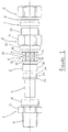
- the component parts of the cable gland termination comprise an entry component 1, a middle nut 2 and a tail nut 3.
- the gland further comprises a compound pot 4 and a rear pot 5 which provide the enclosure for confining the barrier compound as explained later and as shown Figures 3 and 3A.
- a grounding member 6 is associated with the entry component 1 and the middle nut 2.
- a rear seal 7 and washer 8 are associated with the tail nut 3.
- the metal clad cable 9 comprises a plurality of conductor cores 10, an armoured metal sheath 11 of the helically wound type and an outer jacket 12 of any suitable material.
- the terminal end of the cable 9 is prepared so that the conductor cores 10 can be connected to electrical equipment (not shown).
- the ends of the cores 10 are exposed and cut to the required length by removal of a length of the jacket 12 and armour sheath 11, a prescribed length of the armour sheath 11 is exposed by further removal of the covering jacket 12.
- the cores 10 are separated and freed with any other packing or material being removed from around the cores 10.
- the entry component 1 comprises a hollow body having an outer flatted flange 13 for gripping the entry component in use, and the outer end portion 14 of the entry component 1 has an external thread for connection, for example, to the housing of the electrical equipment (not shown).
- the other end portion 15 of the entry component 1 also has an external thread for engagement with the middle nut 2.
- the entry component 1 has a through bore 16 and there is a counter bore 17 at the inner end portion 15 providing an annular shoulder 18.
- the end face of the inner end portion 15 of the entry component 1 is stepped providing an inner annular abutment 19 and an outer annular rib 20.
- the compound pot 4 is arranged to be seated within the entry component 1 to co-operate with the rear pot 5 also seated within the entry component 1 with the exposed cores 10 extending through the pots 4 and 5.
- the compound pot 4 has a through bore 21 with the inner end portion 22 having an annular outer flange 23 arranged to abut the shoulder 18 of the entry component 1. Extending from the flange 23 there is a tapering inner end portion having a relieved outer annular face 24 and an inner taper face 25.
- the relieved annular face 24 of the pot 4 provides, in the assembly, an annular clearance between the inner end of the entry component 1 and the compound pot 4 for receiving one annular end portion 26 of the rear pot 5.
- the other end of the rear pot 5 has a inwardly directed flange 27 having a taper face 28 and a radial end face 29 with a small peripheral relief groove 30. Generally, the radial end face 29 of the rear pot 5 is aligned with the inner abutment 19 on the end face of the entry component 1.
- the middle nut 2 has a hollow body having a through bore with an external flatted flange 31 for use in gripping the middle nut.
- One end portion 32 nearest the entry component 1 is internally threaded to engage the externally threaded end portion 15 of the entry component 1.
- the other end portion 33 extending from the flange 31 has an external thread for engagement with the tail nut 3.
- the end portion 32 is counter-bored along a substantial axial length of the nut body providing an inner shoulder abutment 34.
- the tail nut 3 is of hexagonal or like nut form with flats externally, and has an inner annular recess 35 in which are seated the rear seal 7 and washer 8.
- the tail nut 3 has an internal threaded end portion 36 arranged to engage over the externally threaded end of the middle nut 2.
- the rear seal 7 is of suitable resilient material and is arranged to engage the outer jacket 12 of the cable. The seal 7 is arranged to be engaged by the extreme end face of the end portion 33 of the middle nut 2.
- the grounding member 6 is the component in the gland arranged to provide the electrical continuity from the metallic armoured metal sheath 11 and the gland to the electrical equipment.
- the member 6 comprises a conductive metal ring-like sleeve made of sheet or relatively thin material with the sleeve having a major external diameter to fit inside the middle nut counter bore.
- the grounding member 6 is made of copper or a highly conductive copper based alloy.
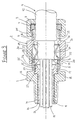
- the grounding member 6 has axially opposed circular abutment ends 37, 38 which are respectively arranged to engage the inner abutment 19 of the entry component 1 and the opposed axially spaced inner shoulder abutment 34 of the middle nut 2 so that the member 6 is trapped there between and on relative threaded engagement and tightening of the middle nut 2 on the entry component 1, the member 6 is squeezed and subject to axial pressure.
- the grounding member 6 has a middle portion 39 which is formed with a series of radially spaced apart elongate apertures 40 that extend generally in an axial or longitudinal direction and which are designed to locally reduce the strength of the middle portion 39 by leaving a series of bridge portions 41 that extend across the middle portion whilst being anchored respectively to the opposed abutment ends 37, 38.
- the central part of the middle portion 39 is formed with a part fold crease 42 extending around the member 6 across all of the bridge portions to create a central zone about which the member 6 will initially fold or collapse when axial pressure is applied to the respective abutment ends 37,38. On such axial pressure, the bridge portions 41 will be displaced inwardly towards the metal sheath 11 and provide one or more discrete contact points engaging and in electrical contact with the metal sheath 11.
- the bridge portions 41 will be displaced on the axial compression of the grounding member until brought into engagement with the surface of the metal sheath 11, but by applying slightly more axial compression by rotating the middle nut slightly more on the entry component 1, further compression will ensure that the bridge portions are extended inwards to be brought into full contact with the metal clad surface at areas where irregularities or non-conformities arise.
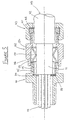
- this shows the barrier gland assembly as just described including the barrier compound 43 in situ being within the compound pot 4 and the co-operating rear pot 5 with the compound filling all of the space and interstices between the conductor cores 10 and filling such space up to the end face of the armoured metal sheath 11 which lies closely to the radial end face 29 of the rear pot 5.
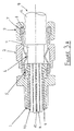
- the gland comprises an entry component 101, a middle nut 102, a tail nut 103 with associated seal 107 and washer 108.
- the entry component 101 and the middle nut 102 are of the same design as in the first embodiment, and a ground member 106 is seated within the middle nut being located on the inner shoulder abutment 134 and engages the inner annular abutment 119 of the entry component 101.
- a stop washer 104 seating against the inner annular shoulder 118 of the entry component 101 with a spacer sleeve 105 extending internally of the inner end portion 115 of the entry component 101.
- the stop washer 104 engages with the cut end of the armour sheath 111 so to prevent this being pulled through the gland.
- the conductor cores 110 extend from and through the stop washer 104 through the open inner end of the entry component 101 for connection to electrical equipment (not shown).
- the cable gland of this embodiment is used after the preparation of the terminal end of the cable 109 by which the jacket 112 is removed to expose the metal cladding 111 and this is then cut back to leave the lengths of conductor cores 110 free and separated for connection.
- the tail nut assembly 103 with washer 108 and seal 107 is slid over the cable 109 followed by the middle nut 102, and the entry component 101 may be fitted to the electrical equipment with the armour stop washer 104 and spacer sleeve 105 received within the counter bored inner end 115 of the entry component.
- the continuity member 106 is pushed over the exposed armour sheath 111 so one abutment end engages with the internal abutment 134 of the middle nut 102.
- the cable 109 is pushed through the entry component 101 until the cut end of the armour sheath is brought into engagement with the stop washer 104.
- the other abutment end of the continuity member 106 engages with the annular abutment face 119 of the entry component.
- the grounding member 106 is subject to axial compressive forces causing the middle portion 139 of reduced strength to fold inwardly so that the bridge portions engage with the outer surface of the armour sheath 111 to ensure electrical contact.
- the tail nut assembly 103 is engaged with the middle nut 102 and tightened so that the seal 107 is brought into firm engagement with the jacket 112 of the cable.
- the deformed bridge portions of the continuity member make more than one good firm electrical contact with the external surface of the armour sheath despite the non-conformities in the surface of the metal cladding.
- grounding member is the same but other forms of grounding members can be provided.
- the apertures which are spaced around the member can be of different shapes, and the spacing to define the bridge portions can be varied depending on the thickness and/or strength of the metal used and the degree of reduced strength required to obtain the required folding and deformation on axially applied loads.
- the continuity member is preferably made from a strip of metal which is stamped and creased as required, and then rolled to form the ring-like grounding member of the required diameter for a particular size of gland.
- FIG. 6 shows the strip development (in plan view) for forming a continuity member as just described.
- View 6A shows the form of the apertures 40 for the continuity member shown and described in the two embodiments previously described.
- the apertures 40 are regularly spaced apart and are of elongate form with part-circular ends leaving the bridge portions 41 of strap-like form extending between the edges 44 of the strip. These edges 44 provide the opposed abutment ends of the continuity member and may be rolled or upset to increase their strength.
- the linear creasing 42 defining the centre zone about which the bridge portions 41 are designed to fold.
- View 6B shows a strip in which the apertures 40B are of long oval form.
- View 6C shows a strip in which the apertures 40C are of lozenge shape and
- View 6D shows another variant in which the apertures 40D have a generally rectangular shape with opposed part-circular extensions in the central region.
- the creasing extends along the centre-line of the strip so that the bridge portions will fold along such crease line.
- apertures may be provided whilst not departing from the concept of providing these spaced apart plurality of bridge portions that are deformed to provide the plurality of discrete contacts to engage with the metal sheath.
- the continuity member can be made to a wide range of sizes to suit different sizes of glands as are required for different sizes of cables.
- the same type of continuity member can be used for a wide range of metal clad cables whilst still ensuring proper electrical contact for grounding (earthing) requirements.
Landscapes
- Cable Accessories (AREA)
- Insulated Conductors (AREA)
Claims (9)
- Presse-étoupe de terminaison pour câble électrique comprenant un composant d'entrée (1 ; 101) pour la connexion à un équipement électrique, un écrou central (2 ; 102) pour s'engager avec le composant d'entrée (1 ; 101) et un écrou arrière (3 ; 103) pour s'engager avec l'écrou central (2 ; 102), un élément de continuité (6 ; 106) situé à l'intérieur de l'écrou central (2 ; 102) et engageant une butée (34 ; 134) dans celui-ci, le composant d'entrée (1 ; 101) ayant une butée d'extrémité (19 ; 119) logée à l'intérieur de l'extrémité de l'écrou central (2 ; 102) éloignée de l'écrou arrière (3 ; 103) avec l'élément de continuité (6 ; 106) engageant également ladite butée d'extrémité (19 ; 119), l'élément de continuité (6 ; 106) ayant une zone centrale (39 ; 139) de résistance réduite pourvue d'une série de portions pleines discrètes (41) séparées par des ouvertures espacées (40), l'agencement étant tel qu'au serrage de l'écrou central (2 ; 102) sur le composant d'entrée (1 ; 101) quand un câble électrique (9 ; 109) s'étend au travers du presse-étoupe avec un placage ou gainage métallique (11 ; 111) exposé à l'intérieur de l'écrou central (2 ; 102), l'élément de continuité (6 ; 106) est soumis à une pression axiale et la zone (39 ; 139) de résistance réduite se plie vers l'intérieur moyennant quoi les portions pleines (41) sont déplacées vers le placage ou gainage métallique (11 ; 111) et à l'engagement avec le placage ou gainage métallique (11 ; 111) fournissent au moins un contact de continuité électrique.
- Presse-étoupe selon la revendication 1, caractérisé en ce que l'élément de continuité (6 ; 106) est réalisé en un métal hautement conducteur, de préférence sélectionné dans le groupe comprenant le cuivre, les alliages de cuivre, l'acier et l'aluminium, et en option galvanisé ou enrobé.
- Presse-étoupe selon l'une quelconque des revendications précédentes, caractérisé en ce que l'élément de continuité (6 ; 106) est formé à partir d'une bande qui est roulée pour former un manchon pourvu d'un pli central (42) autour duquel les portions pleines (41) sont destinées à se plier lorsque la force axiale est appliquée aux extrémités opposées (37, 38) de l'élément de continuité (6).
- Presse-étoupe selon l'une quelconque des revendications précédentes, caractérisé en ce que les ouvertures (40) sont allongées (40 ; 40B ; 40C ; 40D) de manière à s'étendre entre les extrémités opposées (37, 38) de l'élément de continuité (6) et chaque extrémité (37, 38) de l'élément de continuité (6) est de préférence renforcée par un bord périphérique droit ou roulé (44).
- Presse-étoupe de terminaison pour câble électrique comprenant un élément de continuité (6 ; 106) situé dans le presse-étoupe entre des butées internes espacées selon la direction axiale (19, 34 ; 119, 134), l'élément de continuité comprenant un manchon creux ayant une zone (39 ; 139) de résistance réduite formée par des ouvertures espacées (40) qui s'étendent généralement dans la direction axiale du manchon creux pour créer une série de portions pleines discrètes (41) fournissant une pluralité de contacts espacés pour l'engagement avec un placage ou gainage métallique exposé (11 ; 111) d'un câble s'étendant au travers du presse-étoupe, et les parties pleines étant formées avec un pli (42) tel que les parties pleines (41) se plient vers l'intérieur pour être en contact avec le placage ou gainage métallique exposé (11 ;111) du câble (9 ; 109) en réponse à un mouvement axial relatif des butées (19, 34 ; 119, 134) pour appliquer une pression sur l'élément de continuité (6 ; 106).
- Elément de continuité (6 ; 106) pour un presse-étoupe de terminaison pour câble électrique, l'élément de continuité (6 ; 106) comprenant un manchon creux ayant une zone (39 ; 139) de résistance réduite formée par des ouvertures espacées (40) qui s'étendent généralement selon la direction axiale du manchon creux pour créer une série de portions pleines discrètes (41) fournissant une pluralité de contacts espacés pour l'engagement avec un placage ou gainage métallique exposé (11 ; 111) d'un câble (9 ; 109) s'étendant au travers du presse-étoupe dans lequel l'élément de continuité (6 ; 106) est situé, et les portions pleines (41) sont formées avec un pli (42) pour forcer les portions pleines (41) à se plier vers l'intérieur pour entrer en contact avec le placage ou gainage métallique (1 ; 111) en réponse lorsque l'élément de continuité (6 ; 106) est soumis à une compression axiale.
- Procédé d'assemblage d'un presse-étoupe de terminaison pour câble électrique comprenant les étapes consistant à positionner un écrou arrière (3 ; 103) et le joint (7 ; 107) et la rondelle (8 ; 108) associés sur un câble (9 ; 109), monter un écrou central (2 ; 102) sur le câble (9 ; 109) dans une zone où un placage ou gainage métallique (11 ; 111) du câble (9 ; 109) est exposé, positionner un élément de continuité (6 ; 106) à l'intérieur de l'écrou central (2 ; 102), positionner un composant d'entrée (1 ; 101) sur le câble (9 ; 109) dans une zone où au moins une âme conductrice (10 ; 110) du câble (9 ; 109) est exposée et engager l'écrou central (2 ; 102) avec le composant d'entrée (1 ; 101) de manière que l'élément de continuité (6 ; 106) engage des butées internes respectives (19, 34 ; 119, 134) sur le composant d'entrée (1 ; 101) et l'écrou central (2 ; 102), serrer l'écrou central (2 ; 102) sur le composant d'entrée (1 ; 101) pour soumettre l'élément de continuité (6 ; 106) à des forces axiales provoquant un déplacement d'une zone centrale (39 ; 139) de l'élément de continuité (6 ; 106) de résistance réduite formée par une série de portions pleines discrètes (41) séparées par des ouvertures (40) pour amener les portions pleines (41) en contact électrique avec le placage ou gainage métallique (11 ; 111) du câble (9 ; 109) .
- Procédé selon la revendication 7, caractérisé par l'étape consistant à former les portions pleines (41) dans une bande de métal et rouler la bande en un manchon de forme annulaire du diamètre nécessaire pour une taille donnée de presse-étoupe.
- Procédé selon la revendication 8, caractérisé par l'étape consistant à former un pli linaire (42) en travers des portions pleines (41) avant de rouler la bande en manchon.
Applications Claiming Priority (2)
| Application Number | Priority Date | Filing Date | Title |
|---|---|---|---|
| GB9512939A GB2302618B (en) | 1995-06-24 | 1995-06-24 | Electric cable termination gland |
| GB9512939 | 1995-06-24 |
Publications (3)
| Publication Number | Publication Date |
|---|---|
| EP0750376A2 EP0750376A2 (fr) | 1996-12-27 |
| EP0750376A3 EP0750376A3 (fr) | 1998-06-03 |
| EP0750376B1 true EP0750376B1 (fr) | 2004-01-28 |
Family
ID=10776657
Family Applications (1)
| Application Number | Title | Priority Date | Filing Date |
|---|---|---|---|
| EP96304585A Expired - Lifetime EP0750376B1 (fr) | 1995-06-24 | 1996-06-20 | Presse-étoupe de terminaison pour câble électrique |
Country Status (6)
| Country | Link |
|---|---|
| US (1) | US5691505A (fr) |
| EP (1) | EP0750376B1 (fr) |
| AU (1) | AU694356B2 (fr) |
| CA (1) | CA2179568C (fr) |
| DE (1) | DE69631397T2 (fr) |
| GB (1) | GB2302618B (fr) |
Families Citing this family (43)
| Publication number | Priority date | Publication date | Assignee | Title |
|---|---|---|---|---|
| US6682355B1 (en) * | 1998-01-15 | 2004-01-27 | Arlington Industries, Inc. | Electrical fitting for easy snap engagement of cables |
| GB2336041B (en) * | 1998-03-27 | 2002-03-13 | Hawke Cable Glands Ltd | Cable gland |
| DE19848216C2 (de) * | 1998-10-20 | 2001-09-20 | Kleinhuis Hermann Gmbh | Verschraubung zur Ein- und Durchführung sowie Abdichtung von Kabeln, Leitungen, Schläuchen und dergleichen |
| US6254403B1 (en) | 1999-07-30 | 2001-07-03 | Litton Systems, Inc. | Assembly for and method of selectively grounding contacts of a connector to a rear portion of the connector |
| SE515160C2 (sv) * | 1999-10-08 | 2001-06-18 | Roxtec Ab | Kabelgenomföring |
| DE19951455C1 (de) * | 1999-10-25 | 2001-10-25 | Phoenix Contact Gmbh & Co | Kabelanschluss- oder -verbindungseinrichtung |
| ES2225387T3 (es) * | 2000-11-22 | 2005-03-16 | PHOENIX CONTACT GMBH & CO. KG | Dispositivo para conexion o para union de cables. |
| US6796821B2 (en) * | 2002-06-06 | 2004-09-28 | Ocean Design, Inc. | Field installable cable termination assembly |
| US6897383B2 (en) * | 2002-09-19 | 2005-05-24 | Westek Electronics, Inc. | Electrical cable moisture barrier |
| US6878882B2 (en) * | 2002-09-19 | 2005-04-12 | Kevin B. Larkin | Electrical cable moisture barrier with strain relief bridge |
| US7429193B2 (en) * | 2005-12-30 | 2008-09-30 | Ocean Design, Inc. | Harsh environment connector including single-level or dual-level bladder and associated methods |
| US7182617B1 (en) | 2005-12-30 | 2007-02-27 | Ocean Design, Inc. | Harsh environment sealing apparatus for a cable end and cable termination and associated methods |
| ES2334066T3 (es) * | 2007-04-17 | 2010-03-04 | Schlemmer Gmbh | Racor atornillado para cable. |
| AU2007231850B2 (en) * | 2007-11-06 | 2011-02-10 | Ccg Australasia Pty Ltd | Termination Gland for a Shielded Electrical Cable |
| DK2113978T3 (da) * | 2008-04-30 | 2012-09-10 | Abb Technology Ltd | Beskyttelsesindkapsling til et højspændingskabel |
| GB0809953D0 (en) * | 2008-05-31 | 2008-07-09 | Cmp Products Ltd | Cable gland seal |
| AU2009202472A1 (en) * | 2009-06-18 | 2011-01-13 | Ccg Australasia Pty Ltd | A Termination Gland For Shielded Electrical Cables |
| US10193321B2 (en) | 2009-08-21 | 2019-01-29 | Cmp Products Limited | Filler assembly for cable gland |
| SG178839A1 (en) * | 2009-08-21 | 2012-04-27 | Cmp Products Ltd | Filler assembly for cable gland |
| DE202009013522U1 (de) | 2009-10-07 | 2009-12-24 | Hummel Ag | Kabelverschraubung für ein abgeschirmtes Kabel |
| EP2556565B1 (fr) * | 2010-04-09 | 2018-10-03 | Delphi International Operations Luxembourg S.à r.l. | Dispositif de blindage électromagnétique |
| US9123453B2 (en) * | 2010-12-17 | 2015-09-01 | Huber+Suhner Ag | Cable gland |
| DE102010064071B3 (de) * | 2010-12-23 | 2012-05-24 | Tyco Electronics Amp Gmbh | Klemmring, Kabelverschraubung und Verfahren zum Montieren einer Kabelverschraubung |
| US8366459B2 (en) | 2011-03-31 | 2013-02-05 | John Mezzalingua Associates, Inc. | Compression style mid-span ground clamp |
| US20120246920A1 (en) | 2011-03-31 | 2012-10-04 | John Mezzalingua Associates, Inc. | Split compression mid-span ground clamp |
| US8152537B1 (en) | 2011-03-31 | 2012-04-10 | John Mezzalingua Associates, Inc. | Split conductive mid-span ground clamp |
| US8636524B2 (en) | 2011-03-31 | 2014-01-28 | John Mezzalingua Associates, LLC | Split conductive mid-span ground clamp |
| US9696509B2 (en) * | 2011-09-26 | 2017-07-04 | Afl Telecommunications Llc | High reliability armored termination/epoxy gland |
| US8513543B1 (en) * | 2012-02-21 | 2013-08-20 | Asia Tai Technology Co., Ltd. | Water-proofing cable connector |
| BR112013024020B1 (pt) * | 2012-06-15 | 2022-06-28 | João Martins Neto | Prensa-cabo com indicador de aperto |
| DE102012107406A1 (de) * | 2012-08-10 | 2014-05-15 | Endress + Hauser Gmbh + Co. Kg | Anschlussvorrichtung mit Schirmungskontakt |
| DE102015001389B4 (de) | 2014-02-17 | 2023-05-04 | Lear Corporation | Endenabschluss-Vorrichtung für elektromagnetische Abschirmung |
| GB201420990D0 (en) | 2014-11-26 | 2015-01-07 | Rolls Royce Plc | Minerally insulated cable connector |
| US11600976B2 (en) | 2016-10-18 | 2023-03-07 | CAPE Industries, LLC | Cable gland for grounding a cable and method of use |
| US10090653B2 (en) | 2016-10-18 | 2018-10-02 | CAPE Industries, LLC | Cable gland and method and apparatus for earthing a cable |
| US11011896B2 (en) | 2016-10-18 | 2021-05-18 | CAPE Industries, LLC | Cable gland for grounding a cable |
| US10923897B2 (en) * | 2017-03-20 | 2021-02-16 | Pentair Flow Services Ag | Cable sealing gland |
| WO2020096241A1 (fr) * | 2018-11-07 | 2020-05-14 | 엘에스전선 주식회사 | Système de jonction de câble d'alimentation |
| US11018447B2 (en) * | 2019-06-11 | 2021-05-25 | Service Wire Company | Transition coupling for terminating connector and liquidtight conduit fitting |
| US11631971B2 (en) * | 2020-10-19 | 2023-04-18 | CCG International Holdings Limited | Cable gland for armored electrical or fiber optic cables |
| US12308140B2 (en) * | 2020-12-30 | 2025-05-20 | Eaton Intelligent Power Limited | Additively manufactured cable gland |
| WO2023034105A1 (fr) * | 2021-08-30 | 2023-03-09 | Hubbell Incorporated | Joint adaptatif pour presse-étoupe de câble |
| EP4293846A1 (fr) * | 2022-06-13 | 2023-12-20 | NKT HV Cables AB | Dispositif d'étanchéité d'extrémité de câble pour un câble et procédé de connexion d'une gaine metallique d'une extrémité du câble a une enveloppe metallique du dispositif d'étanchéité d'extrémité de câble |
Family Cites Families (16)
| Publication number | Priority date | Publication date | Assignee | Title |
|---|---|---|---|---|
| US1345473A (en) * | 1918-10-18 | 1920-07-06 | Benjamin Electric Mfg Co | Water-tight connection for electrical conductors |
| US1699690A (en) * | 1926-02-08 | 1929-01-22 | Pyle National Co | Connecter |
| GB430356A (en) * | 1933-12-18 | 1935-06-18 | George Arthur Hinds | Improvements relating to flexible pipe connections |
| GB1361492A (en) * | 1972-04-12 | 1974-07-24 | Hawke Cable Glands Ltd | Electrical cable glands |
| US3985418A (en) * | 1974-07-12 | 1976-10-12 | Georg Spinner | H.F. cable socket |
| DE2703306A1 (de) * | 1976-01-29 | 1977-08-04 | Bicc Ltd | Stopfbuchse fuer elektrische kabelanschluesse |
| US4198537A (en) * | 1978-08-21 | 1980-04-15 | Thomas & Betts Corporation | Connector |
| US4273405A (en) * | 1979-08-13 | 1981-06-16 | Thomas & Betts Corporation | Jacketed metal clad cable connector |
| CA1179029A (fr) * | 1982-04-22 | 1984-12-04 | John B. Hutchison | Raccord etanche pour cables electriques |
| US4692562A (en) * | 1985-09-26 | 1987-09-08 | Commander Electrical Materials, Inc. | Seal for a cable connector |
| US4739126A (en) * | 1987-01-16 | 1988-04-19 | Amp Incorporated | Panel mount ground termination apparatus |
| DE3730431A1 (de) * | 1987-09-10 | 1989-03-30 | Amphenol Corp | Kabelverschraubung mit schirmanschluss |
| US4814547A (en) * | 1987-10-06 | 1989-03-21 | Cooper Industries, Inc. | Cable connector |
| FR2630577B1 (fr) * | 1988-04-20 | 1994-03-11 | Capri Codec Sa | Dispositif de mise a la masse de l'armure de cables electriques |
| GB2234306A (en) * | 1989-07-25 | 1991-01-30 | Sergio Marius Julius Meli | Pipe fittings |
| US5278352A (en) * | 1991-07-03 | 1994-01-11 | The United States Of America As Represented By The Secretary Of The Navy | Grounding ring for ground adapters |
-
1995
- 1995-06-24 GB GB9512939A patent/GB2302618B/en not_active Revoked
-
1996
- 1996-06-20 DE DE69631397T patent/DE69631397T2/de not_active Expired - Lifetime
- 1996-06-20 EP EP96304585A patent/EP0750376B1/fr not_active Expired - Lifetime
- 1996-06-20 CA CA002179568A patent/CA2179568C/fr not_active Expired - Lifetime
- 1996-06-21 US US08/667,440 patent/US5691505A/en not_active Expired - Lifetime
- 1996-06-24 AU AU56157/96A patent/AU694356B2/en not_active Expired
Also Published As
| Publication number | Publication date |
|---|---|
| GB2302618B (en) | 1998-11-04 |
| DE69631397T2 (de) | 2004-12-02 |
| US5691505A (en) | 1997-11-25 |
| GB2302618A (en) | 1997-01-22 |
| CA2179568A1 (fr) | 1996-12-25 |
| EP0750376A3 (fr) | 1998-06-03 |
| DE69631397D1 (de) | 2004-03-04 |
| AU694356B2 (en) | 1998-07-16 |
| EP0750376A2 (fr) | 1996-12-27 |
| AU5615796A (en) | 1997-01-09 |
| GB9512939D0 (en) | 1995-08-30 |
| CA2179568C (fr) | 2007-06-19 |
Similar Documents
| Publication | Publication Date | Title |
|---|---|---|
| EP0750376B1 (fr) | Presse-étoupe de terminaison pour câble électrique | |
| EP0093524B1 (fr) | Presse-étoupes pour câble électrique | |
| US5362250A (en) | Coaxial cable connection method and device using oxide inhibiting sealant | |
| EP2774223B1 (fr) | Contact électrique qui présente un motif moleté rhombique | |
| EP3047539B1 (fr) | Ensemble et procédé de connexion de câbles par raccord électrique | |
| EP0468378B1 (fr) | Connexion de terre à plusieurs raccordements | |
| US4415223A (en) | Interlocking crimp sleeve and method of securing to connector | |
| EP2839543B1 (fr) | Systèmes et méthode de connexion de cable | |
| US3992773A (en) | Magnetic forming process for joining electrical connectors and cables | |
| US4921449A (en) | Shield connections for electrical cable connector | |
| CN110582894B (zh) | 用于使屏蔽织物和接触元件接触的接触系统 | |
| EP2115828B1 (fr) | Gaine intérieure moletée pour un connecteur de câble | |
| CA2137413C (fr) | Methode pour la fabrication d'un connecteur de mise a la terre et connecteur de mise a la terre amelioree | |
| EP1206024B1 (fr) | Jonction de câbles utilisant un ensemble tubulaire semi-conducteur et procédé d'obtention d'un connecteur à blindage lisse | |
| US4015329A (en) | Termination of electric cables | |
| US3296363A (en) | Crimped coaxial cable connection with knurled extension | |
| US5646370A (en) | Permanent attachment of grounding wire | |
| EP0008603B1 (fr) | Couplage de ligne pour connecter deux lignes électriques | |
| EP3787119B1 (fr) | Terminal équipé de fils électriques et son procédé de fabrication | |
| CA1239677A (fr) | Epissure de deux conducteurs aluminium de cables electriques, et raccord ainsi faconne | |
| EP2899810A1 (fr) | Cosse | |
| GB2308239A (en) | Lockable insulation piercing connectors | |
| CA2118640C (fr) | Raccord a compression en forme de h | |
| JP2928017B2 (ja) | 扇形導体のスリーブ接続方法 | |
| JPH037891Y2 (fr) |
Legal Events
| Date | Code | Title | Description |
|---|---|---|---|
| PUAI | Public reference made under article 153(3) epc to a published international application that has entered the european phase |
Free format text: ORIGINAL CODE: 0009012 |
|
| AK | Designated contracting states |
Kind code of ref document: A2 Designated state(s): BE DE FR GB |
|
| PUAL | Search report despatched |
Free format text: ORIGINAL CODE: 0009013 |
|
| AK | Designated contracting states |
Kind code of ref document: A3 Designated state(s): BE DE FR GB |
|
| 17P | Request for examination filed |
Effective date: 19981127 |
|
| 17Q | First examination report despatched |
Effective date: 20010514 |
|
| GRAH | Despatch of communication of intention to grant a patent |
Free format text: ORIGINAL CODE: EPIDOS IGRA |
|
| GRAS | Grant fee paid |
Free format text: ORIGINAL CODE: EPIDOSNIGR3 |
|
| GRAA | (expected) grant |
Free format text: ORIGINAL CODE: 0009210 |
|
| AK | Designated contracting states |
Kind code of ref document: B1 Designated state(s): BE DE FR GB |
|
| REG | Reference to a national code |
Ref country code: GB Ref legal event code: FG4D |
|
| REF | Corresponds to: |
Ref document number: 69631397 Country of ref document: DE Date of ref document: 20040304 Kind code of ref document: P |
|
| ET | Fr: translation filed | ||
| PLBE | No opposition filed within time limit |
Free format text: ORIGINAL CODE: 0009261 |
|
| STAA | Information on the status of an ep patent application or granted ep patent |
Free format text: STATUS: NO OPPOSITION FILED WITHIN TIME LIMIT |
|
| 26N | No opposition filed |
Effective date: 20041029 |
|
| BECA | Be: change of holder's address |
Owner name: *HUBBELL LTDMITRE HOUSE, 160 ALDERSGATE STREET, LO Effective date: 20050218 |
|
| REG | Reference to a national code |
Ref country code: FR Ref legal event code: TP |
|
| BECA | Be: change of holder's address |
Owner name: *HUBBELL LTDMITRE HOUSE, 160 ALDERSGATE STREET, LO Effective date: 20050218 |
|
| REG | Reference to a national code |
Ref country code: FR Ref legal event code: PLFP Year of fee payment: 20 |
|
| PGFP | Annual fee paid to national office [announced via postgrant information from national office to epo] |
Ref country code: DE Payment date: 20150630 Year of fee payment: 20 Ref country code: GB Payment date: 20150625 Year of fee payment: 20 |
|
| PGFP | Annual fee paid to national office [announced via postgrant information from national office to epo] |
Ref country code: BE Payment date: 20150629 Year of fee payment: 20 Ref country code: FR Payment date: 20150630 Year of fee payment: 20 |
|
| REG | Reference to a national code |
Ref country code: DE Ref legal event code: R082 Ref document number: 69631397 Country of ref document: DE Representative=s name: WEICKMANN & WEICKMANN PATENT- UND RECHTSANWAEL, DE Ref country code: DE Ref legal event code: R082 Ref document number: 69631397 Country of ref document: DE Representative=s name: WEICKMANN & WEICKMANN PATENTANWAELTE - RECHTSA, DE |
|
| REG | Reference to a national code |
Ref country code: DE Ref legal event code: R071 Ref document number: 69631397 Country of ref document: DE |
|
| REG | Reference to a national code |
Ref country code: GB Ref legal event code: PE20 Expiry date: 20160619 |
|
| PG25 | Lapsed in a contracting state [announced via postgrant information from national office to epo] |
Ref country code: GB Free format text: LAPSE BECAUSE OF EXPIRATION OF PROTECTION Effective date: 20160619 |