EP0750377A1 - Canalisation de montage - Google Patents
Canalisation de montage Download PDFInfo
- Publication number
- EP0750377A1 EP0750377A1 EP96810390A EP96810390A EP0750377A1 EP 0750377 A1 EP0750377 A1 EP 0750377A1 EP 96810390 A EP96810390 A EP 96810390A EP 96810390 A EP96810390 A EP 96810390A EP 0750377 A1 EP0750377 A1 EP 0750377A1
- Authority
- EP
- European Patent Office
- Prior art keywords
- channel
- longitudinal
- guides
- mounting channel
- assembly
- Prior art date
- Legal status (The legal status is an assumption and is not a legal conclusion. Google has not performed a legal analysis and makes no representation as to the accuracy of the status listed.)
- Granted
Links
Images



Classifications
-
- H—ELECTRICITY
- H02—GENERATION; CONVERSION OR DISTRIBUTION OF ELECTRIC POWER
- H02G—INSTALLATION OF ELECTRIC CABLES OR LINES, OR OF COMBINED OPTICAL AND ELECTRIC CABLES OR LINES
- H02G3/00—Installations of electric cables or lines or protective tubing therefor in or on buildings, equivalent structures or vehicles
- H02G3/02—Details
- H02G3/08—Distribution boxes; Connection or junction boxes
- H02G3/10—Distribution boxes; Connection or junction boxes for surface mounting on a wall
- H02G3/105—Distribution boxes; Connection or junction boxes for surface mounting on a wall in association with a plinth, channel, raceway or similar
-
- G—PHYSICS
- G02—OPTICS
- G02B—OPTICAL ELEMENTS, SYSTEMS OR APPARATUS
- G02B6/00—Light guides; Structural details of arrangements comprising light guides and other optical elements, e.g. couplings
- G02B6/44—Mechanical structures for providing tensile strength and external protection for fibres, e.g. optical transmission cables
- G02B6/4439—Auxiliary devices
- G02B6/4459—Ducts; Conduits; Hollow tubes for air blown fibres
-
- G—PHYSICS
- G02—OPTICS
- G02B—OPTICAL ELEMENTS, SYSTEMS OR APPARATUS
- G02B6/00—Light guides; Structural details of arrangements comprising light guides and other optical elements, e.g. couplings
- G02B6/46—Processes or apparatus adapted for installing or repairing optical fibres or optical cables
- G02B6/50—Underground or underwater installation; Installation through tubing, conduits or ducts
- G02B6/508—Fixation devices in ducts for drawing cables
-
- H—ELECTRICITY
- H02—GENERATION; CONVERSION OR DISTRIBUTION OF ELECTRIC POWER
- H02G—INSTALLATION OF ELECTRIC CABLES OR LINES, OR OF COMBINED OPTICAL AND ELECTRIC CABLES OR LINES
- H02G3/00—Installations of electric cables or lines or protective tubing therefor in or on buildings, equivalent structures or vehicles
- H02G3/02—Details
- H02G3/04—Protective tubing or conduits, e.g. cable ladders or cable troughs
- H02G3/0431—Wall trunking
Definitions
- the invention relates to an assembly channel with removable connection elements in a distribution system for electrical cables or optical fibers, in particular for telecommunications and data technology.
- the invention further relates to a spacer for connecting assembly channels.
- connection element In CH, A5 641294, the basic principle of a connection element is described, which has changed little in recent years.
- An insulated wire is electrically conductively connected to a two-leg connection element made of a leaf-shaped, resilient contact material which has a slot.
- the insulated wire is placed in an enlarged insertion opening and pressed into the slot with a suitable tool.
- This slot is bordered by sharp edges and somewhat narrower than the thickness of the metal core of the wire, so that the insulation jacket is cut through when pressed in and a contact connection between the wire and the connecting element is produced.
- insulated wires, cables or fibers can be connected, routed and removed with minimal effort, depending on requirements and coordinated with the cabling of the corresponding connector.
- connection elements for telecommunications and data technology are described in EP, Al 0382322 and 0446572, which also work with insulation displacement contacts.
- A1 0382322 a shield connection element made of a U-shaped sheet metal part is provided for connecting shielded cables.
- the second EP, A1 0446572 discloses a connection element with two strip bodies, at least one strip body being provided with an axis of rotation. The strip body can be swiveled out of the connection strip, making the assembly duct partially accessible.
- the present invention has for its object to provide a mounting channel of the type mentioned, which facilitates the connection, maneuvering and removal of insulated electrical cables or optical fibers on connection elements and in particular allows quick, complete access with easy handling without the use of other aids. Furthermore, spacers are to be created which allow a problem-free, train-safe assembly of several assembly channels.
- the object is achieved according to the invention in that the assembly channel, which is essentially U-shaped in cross section, has longitudinally extending guides with cylindrical jacket-shaped guides on both sides of the longitudinal opening Has surface, and the connection elements are pivotally mounted on the guides.
- connection elements All products available on the market, in particular also those described in the prior art mentioned in the introduction, can be used as connection elements, provided they have means for pivoting on at least one longitudinal guide and preferably for shifting in the longitudinal direction.
- connection elements preferably have two pairs of spring legs, which can be plugged onto the longitudinal guides of the mounting channel with their cylindrical jacket-shaped surface.
- the pairs of spring legs On the inside, the pairs of spring legs have a rounding corresponding to the radius of the guides.
- the spring legs are spread slightly and snap into the end position with the curves.
- the spring legs are simultaneously used as a means for pivoting.
- the connection element can optionally be pivoted to both sides by loosening one or the other clip connection, while the other clip connection still comprises the longitudinal guide, which forms an axis of rotation.
- the longitudinal guides of the mounting channel and the spring legs of a connecting element are expediently designed such that it can be turned off by at least 90 ° to one side or the other.
- the entire assembly channel is exposed in sections or completely, depending on the number of pivoted connection elements. Each individual twisted connection element is in turn easily accessible.
- a round tube or a round rod is fastened on the opening edge forming the longitudinal opening in the assembly channel. This can be done with a continuous weld seam or with individual weld spots at a distance of, for example, 10 to 20 cm.
- the round bar or the round tube lies approximately tangentially in the plane of the adjacent inner surface of the assembly channel. On the one hand, this enables a pivoting range of the connecting element of at least 90 ° to be achieved without problems, and on the other hand, the longitudinal opening in the assembly channel is retained over its full width.
- this longitudinal guide can be attached by spot welding according to a second variant at a distance from the assembly channel.
- the connecting element can thus enter the space between the round rod or round tube and the mounting channel when swinging out with a spring leg, thus increasing the swing-out angle to well over 90 °. This improves access to the assembly channel, but disadvantages also have to be accepted.
- the connecting element can only be displaced longitudinally in the closed or slightly opened state; when swung out fully, the longitudinal displaceability is limited to the area between two welding points. If the round rod or the round tube is not welded tangentially to the inner surface of the assembly channel, the accessibility of this channel is restricted with respect to the width.
- the ends of the side wall can be bent outwards in accordance with a third variant in such a way that a round tubular flare arises.
- This solution is functionally equivalent to a welded-in round tube according to the first variant.
- a round tube is preferred over a corresponding rod because it has less weight with practically the same mechanical strength, which means cost savings and easier handling. Furthermore, rolls with cable reserve, tools or the like can be inserted into tubular, longitudinal guides.
- the rear wall and / or at least one side wall preferably has hooks punched out for easy hanging of insulated wires, cables or fibers, it also being possible, of course, to hang in cable ties.
- the mounting channels have oval and rear holes on the side for fastening the channels, which holes are also provided for the internal mounting of the installation cables and wires.
- the necessary looping through is tedious and time-consuming, in contrast to the mentioned further development of the assembly channel according to the invention, which only requires simple hooking.
- the hooks are T-shaped, L-shaped, mushroom-shaped or hat-shaped, for example, preventing slipping out is essential.
- lateral recesses for fastening spacers which also serve as cable carriers, are preferably punched out in the form of a regular polygon, each with two parallel sides, expediently as a square, but also as a hexagon. Such recesses are suitable for receiving a spacer which can be clamped with one of the systems described below.
- the object is achieved according to the invention in that the two end areas correspond in cross-section to the recesses in the channel side walls and have at least one circumferential groove corresponding to the thickness of these walls, which forms a clamp or snap connection when the spacer is rotated over the lateral surface of the groove web.
- the depth of the groove is determined by the lateral surface of a groove web. When inserting the spacer, this groove bar is exposed over the entire circumference. When the spacer is rotated, the lateral surface of the groove web approaches the edge of the recess in the channel side wall and finally forms a snap or clamp closure.
- the spacers can be quickly inserted and removed without tools and without complicated screw connections.
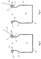
- FIG. 1 shows an assembly channel 10 which is essentially U-shaped and has a longitudinal opening 12. This longitudinal opening 12 is somewhat narrowed by an obliquely angled step 14 relative to the interior 16 of the mounting channel.
- Two parallel longitudinal guides 18 with a cylindrical jacket-shaped surface, in the present example in the form of round tubes, are welded along the longitudinal opening 12. The two round tubes lie approximately tangentially on the inner surface 20 of the mounting channel 10 in the region of the longitudinal opening 12.
- connection element 22 is shown, which is designed in a manner known per se, for example according to EP, A1 0382322 or 0446572
- Connection element 22 preferably comprises insulation displacement contact elements known to the person skilled in the art for connecting, marshalling or removing insulated, electrically conductive wires, cables or optical fibers.
- a connector also known per se, not shown
- a connector can be attached, also using a coding system according to EP, A1 0573396.
- the connecting element 22 now comprises two pairs of spring legs 26 which are clipped onto the longitudinally running tubes 18.
- the side of the spring legs 26 facing the tube 18 is rounded off accordingly.
- FIG. 2 shows the connecting element 22 pivoted by a little more than 90 °.
- the pair of spring legs 26 on the left in the drawing is disengaged, the connecting element 22 can now pivot about the axis R of the tube 18 using the spring legs 26.
- connection element 22 could also be clipped out on the right and pivoted around the left tube 18. In principle, the two solutions are equivalent. However, the connection element 22 is cabled such that both the input and the output connections run adjacent to a selected axis of rotation R.
- the round tubular guides 18 are welded at a distance from the opening edge 28 of the assembly channel 10. This is done via welding spots arranged at a distance of 10 to 20 cm, of which on the left side one is indicated by a dashed line, it lies outside the cutting plane.
- An open connection element 22 is partially shown on the right side. It can be clearly seen how a spring leg 26 extends through the space between an opening edge 28 of the longitudinal opening 12 and the tube 18. Therefore, the connection element 22 can be opened further, namely a little over 120 °.
- the completely opened connection element can only be moved between two welding points 30 in the longitudinal direction of the axis R. For larger longitudinal displacements, the connection element 22 must be closed at least partially.
- the end of the side walls 40 of the mounting channel 10 with the opening edge 28 (FIG. 3) is bent in a circle and thus forms a flange which forms the longitudinal guide 18.
- the connecting element 22 can be pivoted around this functionally equivalent flanging with a tube.
- a rear wall 32 of an assembly channel 10 shown in FIG. 5 shows, in addition to the usual punched-outs in the form of elongated holes 34 which are also referred to as oval, hooks 36 punched out in rows, in the present case T-shaped, which leads to undercut spaces 38. Cable loops or the like can be inserted into these without having to laboriously and time-consuming having to loop through several openings corresponding to the elongated holes 34.
- a side wall 40 of an assembly channel 10 shown in FIG. 6 shows the obliquely angled step 14.
- notches 42 are cut out at regular intervals, they are used for spot welding for fastening a longitudinal guide 18 (FIGS. 1 to 4).
- Extending over the entire length of the side wall 40 are square-shaped recesses 44 of a side length b, which are the anchorage of spacers.
- hooks 36 can also be punched out analogously to the rear wall 32 (FIG. 5).
- a spacer 48 shown in FIGS. 7 to 9 is, viewed from the side, a superscript square with vertical and horizontal diagonals of length d.
- the end regions each comprise two circumferential grooves 50 and a long, relatively narrow central web 52.
- the outer walls of the grooves 50 do not run parallel, but are slightly open towards the outside, which is shown in FIG. 9 with an angle a of approximately 5 °. This facilitates anchoring after insertion of a spacer 48 into a square recess 44 (FIG. 6) of the channel side wall 40.
- a groove web 54 with a circumferential groove jacket 58, the groove bottom, is the means for forming the clamp or snap connection.
- the spacer 48 is rotated until it jams or snaps into place.
- the thickness of the metallic side wall 40 in the present example corresponds to the width of the grooves 50 of the spacer 48 made of plastic.
- the snap-in can take place thanks to the square shape of the recess 44 (FIG. 6) and the octagonal design of the groove webs 54.
- the lateral surface 58 of the groove web 54 has, in section according to FIG. 10, two parallel longer side pairs and two shorter side pairs.
- the shorter side pairs arranged in the corner regions of the square at an angle of 45 ° have a distance b, corresponding to the side length of the square recess 44 (FIG. 6).
- All edges 62 of the octagonal groove web 54 are rounded, their apex must lie a little further, for example 0.5-1 mm, from its longitudinal center axis L than half the side length b of the square recess 44 (FIG. 6).
- the lateral surface 58 of the groove web 54 is increasingly approaching the square border of the recess 44 until it rests at two diagonally opposite locations.
- at least the diagonal apex 60 must be further away from the center of the square than its half side length b.
- the depth t of the groove 50 in the diagonal direction must not be greater than half the diagonal d, reduced by half the side length b of the square.
- the grooves 50 of a spacer 48 are formed in pairs at both ends, because the distance between the mounting channels can be varied.
Landscapes
- Physics & Mathematics (AREA)
- Engineering & Computer Science (AREA)
- Architecture (AREA)
- Civil Engineering (AREA)
- Structural Engineering (AREA)
- General Physics & Mathematics (AREA)
- Optics & Photonics (AREA)
- Light Guides In General And Applications Therefor (AREA)
- Sewage (AREA)
- Vehicle Body Suspensions (AREA)
- Coupling Device And Connection With Printed Circuit (AREA)
- Piezo-Electric Or Mechanical Vibrators, Or Delay Or Filter Circuits (AREA)
Applications Claiming Priority (3)
| Application Number | Priority Date | Filing Date | Title |
|---|---|---|---|
| CH01848/95A CH689848A5 (de) | 1995-06-23 | 1995-06-23 | Montagekanal. |
| CH184895 | 1995-06-23 | ||
| CH1848/95 | 1995-06-23 |
Publications (2)
| Publication Number | Publication Date |
|---|---|
| EP0750377A1 true EP0750377A1 (fr) | 1996-12-27 |
| EP0750377B1 EP0750377B1 (fr) | 2001-01-24 |
Family
ID=4220028
Family Applications (1)
| Application Number | Title | Priority Date | Filing Date |
|---|---|---|---|
| EP96810390A Expired - Lifetime EP0750377B1 (fr) | 1995-06-23 | 1996-06-13 | Canalisation de montage |
Country Status (4)
| Country | Link |
|---|---|
| EP (1) | EP0750377B1 (fr) |
| AT (1) | ATE198955T1 (fr) |
| CH (1) | CH689848A5 (fr) |
| DE (1) | DE59606362D1 (fr) |
Cited By (1)
| Publication number | Priority date | Publication date | Assignee | Title |
|---|---|---|---|---|
| WO2025125701A1 (fr) * | 2023-12-12 | 2025-06-19 | Unex Aparellaje Electrico S.L. | Ensemble formant porte-câbles, et composant porte-câbles correspondant |
Families Citing this family (1)
| Publication number | Priority date | Publication date | Assignee | Title |
|---|---|---|---|---|
| ES2413564B1 (es) * | 2011-12-14 | 2014-03-05 | Simon, S.A. | Sistema de anclaje de un bastidor a una envolvente para mecanismos eléctricos |
Citations (3)
| Publication number | Priority date | Publication date | Assignee | Title |
|---|---|---|---|---|
| EP0446572A1 (fr) * | 1990-03-13 | 1991-09-18 | KRONE Aktiengesellschaft | Bloc de connexion pour technique des télécommunications et de l'informatique |
| DE9406359U1 (de) * | 1994-04-16 | 1994-06-16 | Albert Ackermann Gmbh & Co Kg, 51643 Gummersbach | Installationsgehäuse |
| DE9406088U1 (de) * | 1994-04-13 | 1994-06-16 | Hermann Kleinhuis GmbH & Co KG, 58507 Lüdenscheid | Kabelkanal, insbesondere Sockelleistenkanal |
-
1995
- 1995-06-23 CH CH01848/95A patent/CH689848A5/de not_active IP Right Cessation
-
1996
- 1996-06-13 DE DE59606362T patent/DE59606362D1/de not_active Expired - Lifetime
- 1996-06-13 AT AT96810390T patent/ATE198955T1/de not_active IP Right Cessation
- 1996-06-13 EP EP96810390A patent/EP0750377B1/fr not_active Expired - Lifetime
Patent Citations (3)
| Publication number | Priority date | Publication date | Assignee | Title |
|---|---|---|---|---|
| EP0446572A1 (fr) * | 1990-03-13 | 1991-09-18 | KRONE Aktiengesellschaft | Bloc de connexion pour technique des télécommunications et de l'informatique |
| DE9406088U1 (de) * | 1994-04-13 | 1994-06-16 | Hermann Kleinhuis GmbH & Co KG, 58507 Lüdenscheid | Kabelkanal, insbesondere Sockelleistenkanal |
| DE9406359U1 (de) * | 1994-04-16 | 1994-06-16 | Albert Ackermann Gmbh & Co Kg, 51643 Gummersbach | Installationsgehäuse |
Cited By (1)
| Publication number | Priority date | Publication date | Assignee | Title |
|---|---|---|---|---|
| WO2025125701A1 (fr) * | 2023-12-12 | 2025-06-19 | Unex Aparellaje Electrico S.L. | Ensemble formant porte-câbles, et composant porte-câbles correspondant |
Also Published As
| Publication number | Publication date |
|---|---|
| CH689848A5 (de) | 1999-12-15 |
| EP0750377B1 (fr) | 2001-01-24 |
| ATE198955T1 (de) | 2001-02-15 |
| DE59606362D1 (de) | 2001-03-01 |
Similar Documents
| Publication | Publication Date | Title |
|---|---|---|
| DE60019037T2 (de) | Erdungsfeder und Erdungssystem | |
| DE2730980C3 (de) | Verankerungsvorrichtung für elektrische Verbindungsteile | |
| DE69517476T2 (de) | Verkabelungsvorrichtung eines elektrischen Anschlusskasten, Verfahren und Vorrichtung zur Bildung der Verkabelung | |
| EP2176931B1 (fr) | Rigole grillagée et raccord pour rigole grillagée, ainsi que procédé de fabrication de cette rigole grillagée | |
| DE2301625A1 (de) | Die isolierung und das oxid durchstossendes kontaktelement | |
| DE1575315A1 (de) | Aufhaenger | |
| DE69427781T2 (de) | Miteinander verbundene elektrische Anschlussklemmenanordnung | |
| DE69507583T2 (de) | Elektrisches Kabel zur Verwendung mit Schneidklemmen und elektrische Verbindungselemente | |
| DE69505593T2 (de) | Schneidklemmverbinder | |
| DE1993998U (de) | Elektrischer klemmenblock. | |
| DE60310773T2 (de) | Mehrfachabzweigpressverbinder | |
| DE7137853U (de) | Federklammer fur elektrische Flach Steckerverbindungen | |
| EP1376795A2 (fr) | Dispositif d'installation de conducteurs d'énergie | |
| DE2427444C2 (de) | Bauwerksknoten | |
| EP0617493A1 (fr) | Dispositif de liaison pour gouttieres en grille | |
| DE8704051U1 (de) | Vorrichtung zum nachträglichen Einziehen von Kabeln in Kabelschutzrohre | |
| EP0750377B1 (fr) | Canalisation de montage | |
| DE10035795B4 (de) | Klemmschuhanordnung | |
| DE2714158C2 (de) | Anschlußvorrichtung für ein vieladriges Kabel | |
| EP0809325B1 (fr) | Dispositif d'installation électrique et borne de connexion pour le dispositif | |
| AT409564B (de) | Anschlussdose für ein datennetz | |
| DE3782485T2 (de) | Isolierender abstandshalter fuer gasisoliertes elektrisches geraet. | |
| DE1907950B2 (de) | Isolationsauftrennende kontaktklemme | |
| EP0294680B1 (fr) | Boîtier avec bornes de connexion | |
| DE2551300B2 (de) | Klemmhuelse einer schraubklemme fuer elektrische leitungen |
Legal Events
| Date | Code | Title | Description |
|---|---|---|---|
| PUAI | Public reference made under article 153(3) epc to a published international application that has entered the european phase |
Free format text: ORIGINAL CODE: 0009012 |
|
| AK | Designated contracting states |
Kind code of ref document: A1 Designated state(s): AT BE CH DE LI LU NL |
|
| 17P | Request for examination filed |
Effective date: 19970610 |
|
| RAP1 | Party data changed (applicant data changed or rights of an application transferred) |
Owner name: DRAHTEX AG |
|
| 17Q | First examination report despatched |
Effective date: 19990930 |
|
| GRAG | Despatch of communication of intention to grant |
Free format text: ORIGINAL CODE: EPIDOS AGRA |
|
| GRAG | Despatch of communication of intention to grant |
Free format text: ORIGINAL CODE: EPIDOS AGRA |
|
| GRAH | Despatch of communication of intention to grant a patent |
Free format text: ORIGINAL CODE: EPIDOS IGRA |
|
| GRAH | Despatch of communication of intention to grant a patent |
Free format text: ORIGINAL CODE: EPIDOS IGRA |
|
| GRAA | (expected) grant |
Free format text: ORIGINAL CODE: 0009210 |
|
| AK | Designated contracting states |
Kind code of ref document: B1 Designated state(s): AT BE CH DE LI LU NL |
|
| PG25 | Lapsed in a contracting state [announced via postgrant information from national office to epo] |
Ref country code: NL Free format text: LAPSE BECAUSE OF FAILURE TO SUBMIT A TRANSLATION OF THE DESCRIPTION OR TO PAY THE FEE WITHIN THE PRESCRIBED TIME-LIMIT Effective date: 20010124 |
|
| REF | Corresponds to: |
Ref document number: 198955 Country of ref document: AT Date of ref document: 20010215 Kind code of ref document: T |
|
| REG | Reference to a national code |
Ref country code: CH Ref legal event code: EP |
|
| REG | Reference to a national code |
Ref country code: CH Ref legal event code: NV Representative=s name: PATENTANWAELTE BREITER + WIEDMER AG |
|
| REF | Corresponds to: |
Ref document number: 59606362 Country of ref document: DE Date of ref document: 20010301 |
|
| PG25 | Lapsed in a contracting state [announced via postgrant information from national office to epo] |
Ref country code: LU Free format text: LAPSE BECAUSE OF NON-PAYMENT OF DUE FEES Effective date: 20010613 |
|
| EN | Fr: translation not filed | ||
| PG25 | Lapsed in a contracting state [announced via postgrant information from national office to epo] |
Ref country code: BE Free format text: LAPSE BECAUSE OF NON-PAYMENT OF DUE FEES Effective date: 20010630 |
|
| NLV1 | Nl: lapsed or annulled due to failure to fulfill the requirements of art. 29p and 29m of the patents act | ||
| PLBE | No opposition filed within time limit |
Free format text: ORIGINAL CODE: 0009261 |
|
| STAA | Information on the status of an ep patent application or granted ep patent |
Free format text: STATUS: NO OPPOSITION FILED WITHIN TIME LIMIT |
|
| BERE | Be: lapsed |
Owner name: DRAHTEX A.G. Effective date: 20010630 |
|
| 26N | No opposition filed | ||
| REG | Reference to a national code |
Ref country code: CH Ref legal event code: PUE Owner name: FRIDOLIN ALOIS FRECH Free format text: DRAHTEX AG#SCHOENTALSTRASSE 23#8486 RIKON (CH) -TRANSFER TO- FRIDOLIN ALOIS FRECH#IM RAIN 5#8488 TURBENTHAL (CH) Ref country code: CH Ref legal event code: NV Representative=s name: BREITER + PARTNER AG PATENT - UND MARKENBUERO |
|
| REG | Reference to a national code |
Ref country code: CH Ref legal event code: PFA Owner name: FRIDOLIN ALOIS FRECH Free format text: FRIDOLIN ALOIS FRECH#IM RAIN 5#8488 TURBENTHAL (CH) -TRANSFER TO- FRIDOLIN ALOIS FRECH#IM RAIN 5#8488 TURBENTHAL (CH) |
|
| PGFP | Annual fee paid to national office [announced via postgrant information from national office to epo] |
Ref country code: CH Payment date: 20080620 Year of fee payment: 13 |
|
| PGFP | Annual fee paid to national office [announced via postgrant information from national office to epo] |
Ref country code: AT Payment date: 20080626 Year of fee payment: 13 |
|
| PGFP | Annual fee paid to national office [announced via postgrant information from national office to epo] |
Ref country code: DE Payment date: 20080710 Year of fee payment: 13 |
|
| PG25 | Lapsed in a contracting state [announced via postgrant information from national office to epo] |
Ref country code: DE Free format text: LAPSE BECAUSE OF THE APPLICANT RENOUNCES Effective date: 20090606 |
|
| REG | Reference to a national code |
Ref country code: CH Ref legal event code: PL |
|
| PG25 | Lapsed in a contracting state [announced via postgrant information from national office to epo] |
Ref country code: LI Free format text: LAPSE BECAUSE OF NON-PAYMENT OF DUE FEES Effective date: 20090630 Ref country code: CH Free format text: LAPSE BECAUSE OF NON-PAYMENT OF DUE FEES Effective date: 20090630 |
|
| PG25 | Lapsed in a contracting state [announced via postgrant information from national office to epo] |
Ref country code: AT Free format text: LAPSE BECAUSE OF NON-PAYMENT OF DUE FEES Effective date: 20090613 |