EP0750377B1 - Montagekanal - Google Patents
Montagekanal Download PDFInfo
- Publication number
- EP0750377B1 EP0750377B1 EP96810390A EP96810390A EP0750377B1 EP 0750377 B1 EP0750377 B1 EP 0750377B1 EP 96810390 A EP96810390 A EP 96810390A EP 96810390 A EP96810390 A EP 96810390A EP 0750377 B1 EP0750377 B1 EP 0750377B1
- Authority
- EP
- European Patent Office
- Prior art keywords
- duct
- installation
- installation duct
- channel
- longitudinal
- Prior art date
- Legal status (The legal status is an assumption and is not a legal conclusion. Google has not performed a legal analysis and makes no representation as to the accuracy of the status listed.)
- Expired - Lifetime
Links
Images


Classifications
-
- H—ELECTRICITY
- H02—GENERATION; CONVERSION OR DISTRIBUTION OF ELECTRIC POWER
- H02G—INSTALLATION OF ELECTRIC CABLES OR LINES, OR OF COMBINED OPTICAL AND ELECTRIC CABLES OR LINES
- H02G3/00—Installations of electric cables or lines or protective tubing therefor in or on buildings, equivalent structures or vehicles
- H02G3/02—Details
- H02G3/08—Distribution boxes; Connection or junction boxes
- H02G3/10—Distribution boxes; Connection or junction boxes for surface mounting on a wall
- H02G3/105—Distribution boxes; Connection or junction boxes for surface mounting on a wall in association with a plinth, channel, raceway or similar
-
- G—PHYSICS
- G02—OPTICS
- G02B—OPTICAL ELEMENTS, SYSTEMS OR APPARATUS
- G02B6/00—Light guides; Structural details of arrangements comprising light guides and other optical elements, e.g. couplings
- G02B6/44—Mechanical structures for providing tensile strength and external protection for fibres, e.g. optical transmission cables
- G02B6/4439—Auxiliary devices
- G02B6/4459—Ducts; Conduits; Hollow tubes for air blown fibres
-
- G—PHYSICS
- G02—OPTICS
- G02B—OPTICAL ELEMENTS, SYSTEMS OR APPARATUS
- G02B6/00—Light guides; Structural details of arrangements comprising light guides and other optical elements, e.g. couplings
- G02B6/46—Processes or apparatus adapted for installing or repairing optical fibres or optical cables
- G02B6/50—Underground or underwater installation; Installation through tubing, conduits or ducts
- G02B6/508—Fixation devices in ducts for drawing cables
-
- H—ELECTRICITY
- H02—GENERATION; CONVERSION OR DISTRIBUTION OF ELECTRIC POWER
- H02G—INSTALLATION OF ELECTRIC CABLES OR LINES, OR OF COMBINED OPTICAL AND ELECTRIC CABLES OR LINES
- H02G3/00—Installations of electric cables or lines or protective tubing therefor in or on buildings, equivalent structures or vehicles
- H02G3/02—Details
- H02G3/04—Protective tubing or conduits, e.g. cable ladders or cable troughs
- H02G3/0431—Wall trunking
Definitions
- the invention relates to a mounting channel with removable Connection elements in a distribution system for electrical cables or optical fibers, especially for the Telecommunications and data technology.
- the invention further relates to a spacer for connecting assembly channels.
- U1 0406359 describes a wall installation duct with a housing profile open on one side for the in and Expansion of electrical installation equipment and with one Hinged lid on the open side. There is a on one side wall cylindrical bead formed with flats on which with at least one pressure spring a claw of Hinged lid is pressed. So the hinged lid can be hinge-like be opened.
- the electrotechnical installation devices cannot be swiveled.
- connection element In CH, A5 641294 the basic principle of a connection element described what has changed in recent years changed little.
- An insulated wire comes with a two legs having connection element from one leaf-shaped, springy contact material, which a Has slot, electrically connected. This will the insulated wire is placed in an enlarged insertion opening and pressed into the slot with a suitable tool. This slot is bordered by sharp edges and somewhat tighter than the strength of the metal core of the wire, so that cut through when pressing in the insulation jacket and a contact connection between the wire and the connection element will be produced. This results in a quick, easily detachable connection, which also insulation displacement contact is called. With these contacts can be isolated Wires, cables or fibers connected with minimal effort, be shunted and removed as required and coordinates with the cabling of the corresponding connector.
- connection elements for telecommunication and Data technology are described in EP, Al 0382322 and 0446572, which also work with insulation displacement contacts.
- A1 0382322 is shielded for connection Cable a shield connection element from a U-shaped bent sheet metal part provided.
- A1 0446572 is a connection element with two strip bodies discloses, wherein at least one last body with a Axis of rotation is provided. So is the last body from the terminal block can be swung out, creating the mounting channel partially accessible.
- the present invention has for its object a To create mounting channel of the type mentioned, which connecting, maneuvering and removing insulated electrical cables or optical fibers on connection elements relieved and in particular a quick, complete Access with ease of use without use other aids allowed. Spacers should continue be created, which is a problem-free, train-secured Allow assembly of several assembly channels.
- connection elements are all available on the market Products, especially those mentioned in the introduction State of the art described, usable, provided they are means for swiveling on at least one longitudinal guide and preferably for longitudinal displacement.
- connection elements preferably have two pairs of spring legs, which on the longitudinal guides of the Assembly channel with its cylindrical surface are attachable.
- the pair of spring legs point on the inside a rounding corresponding to the radius of the guides.
- clipping also called clipping
- the spring legs slightly spread and snap in the end position with the curves.
- the connection element can optionally be swiveled to both sides be by one or the other clip connection is released while the other clip connection always still includes the longitudinal guide, which has an axis of rotation forms.
- connection element The longitudinal guides of the assembly channel and the spring legs a connection element are expedient designed that this at least 90 ° after the one or other side can be turned off. That's the whole way Assembly channel by sector or completely exposed, each according to the number of connecting elements swung out. Each individual twisted connection element is in turn easily accessible.
- the longitudinal opening in the A round tube or a mounting channel forming the opening edge Round bar attached can be done with a continuous Weld seam or with individual welding points in one Distance of 10 to 20 cm, for example.
- the round rod lies in a particularly advantageous embodiment or the round tube approximately tangentially in the plane of the adjacent one Inner surface of the assembly channel. This will on the one hand a pivoting range of the connection element of at least 90 ° easily reached, on the other hand, the longitudinal opening remains preserved in their full width in the assembly channel.
- connection element can only be moved longitudinally when closed or slightly open, when swung out fully, the Longitudinal displacement on the area between two Welding spots. If the round bar or the round tube is not welded tangential to the inner surface of the assembly channel is the accessibility of this channel with respect to the Limited width.
- a round tube is opposed to a corresponding one Rod preferred because it is practically the same mechanical Strength has less weight, which is a Cost savings and easier handling means.
- tubular, longitudinal guides Rolls with cable reserve, tools or the like can be inserted.
- the rear wall and / or at least one Side wall punched out hooks for easy hanging of insulated wires, cables or fibers, where Of course, cable ties can also be attached.
- the mounting channels oval and rear holes for fastening of the channels on which holes also for internal attachment the installation cables and wires are provided. The looping through is tedious and time-consuming Contrary to the mentioned training of the inventive Mounting channel, which is only a simple hook makes necessary.
- the hooks are, for example T, L, mushroom or hat-shaped, essential is a prevention of slipping out.
- lateral recesses for fastening of spacers which also serve as cable carriers preferably in the form of a regular polygon with each punched out two parallel sides, practical as a square, but also as a hexagon.
- Such recesses are suitable for holding a spacer, which with one of the systems described below can be clamped is.
- the task according to the invention is to connect assembly channels solved in that both forehead areas cross-section correspond to the recesses in the channel side walls and at least one corresponding to the thickness of these walls have circumferential groove, which when turning the spacer a clamping or over the lateral surface of the groove web Snap connection forms.
- the depth of the groove is determined by the lateral surface of a groove web certainly. When inserting the spacer this slot bar is free over the entire circumference. When turning the Spacer approaches the lateral surface of the grooved web more and more the border of the recess in the channel side wall and finally forms a snap or clamp closure.
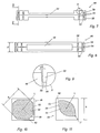
- Fig. 1 shows a mounting channel 10, which is essentially Is U-shaped and has a longitudinal opening 12. This longitudinal opening 12 is angled at an angle Level 14 compared to the interior 16 of the mounting channel somewhat constricted. Two are parallel along the longitudinal opening 12 longitudinal guides 18 with a cylindrical surface, in the present example in the form of round tubes, welded on. The two round tubes are approximately tangential on the inner surface 20 of the mounting channel 10 in the area of Longitudinal opening 12.
- connection element 22 which is designed in a manner known per se, for example according to EP, A1 0382322 or 0446572.
- Das Connection element 22 preferably comprises those known to the person skilled in the art Insulation displacement contact elements for connection, Maneuvering or removing insulated, electrically conductive Wires, cables or optical fibers.
- Towards the Arrow 24 can also be a known one, not shown Plugs can be put on, also using a coding system according to EP, A1 0573396.
- the connecting element 22 now comprises two pairs of spring legs 26, which are clipped onto the longitudinal tubes 18.
- the side of the spring leg facing the tube 18 is 26 rounded accordingly.
- Fig. 2 shows the connection element pivoted by a little more than 90 ° 22.
- the pair of spring legs 26 on the left in the drawing is disengaged, the connecting element 22 can now be used the spring leg 26 about the axis R of the tube 18th swing.
- connection element 22 On the left side of Fig. 2 it is indicated that the connection element 22 also clipped out on the right and around the left Tube 18 could be pivoted.
- the two solutions are in Equivalent principle.
- the wiring of the connection element 22, however, is such that both the input and the output ports adjacent a selected axis of rotation R run.
- connection element 22 is the round tubular guides 18 welded at a distance from the opening edge 28 of the assembly channel 10. This is done at a distance of 10 to 20 cm arranged welding spots, of which on the left side one is indicated by dashed lines, it lies outside the Cutting plane.
- On the right side is an open connection element 22 partially shown. It is clear to see like a spring leg 26 the space between an opening edge 28 of the longitudinal opening 12 and the tube 18th reaches through. Therefore, the connection element 22 can continue be opened, namely a little over 120 °.
- the connecting element 22 must at least have longitudinal displacements partially closed.
- a rear wall 32 of an assembly channel shown in FIG. 5 10 shows in addition to the usual punched-outs in the form of as oval slots 34 punched out in a row Hooks 36, in the present case T-shaped, which leads to undercut rooms 38.
- these cable loops or the like can be inserted without tedious and time-consuming several corresponding to the elongated holes 34 Openings have to be looped through.
- a side wall 40 of an assembly channel shown in FIG. 6 10 shows the obliquely angled step 14. At the Opening edge 28 are notches at regular intervals 42 recessed, they are used for spot welding for fastening a longitudinal guide 18 (Fig. 1 to 4). About the entire length of the side wall 40 extend square Recesses 44 of a side length b, which the anchorage of spacers.
- Holes 46 are provided for press-in nuts. Of course can, similarly to the rear wall 32 (FIG. 5), hooking 36 be punched out.
- a spacer 48 shown in FIGS. 7 to 9 is from viewed from the side, a superscript square with vertical and horizontal diagonal of length d.
- the front Areas each include two circumferential grooves 50 and a long, relatively narrow central web 52 Outer walls of the grooves 50 do not run parallel, but instead are slightly open to the outside, which in Fig. 9 with a Angle ⁇ of about 5 ° is shown. This eases after inserting a spacer 48 into a square Recess 44 (Fig. 6) of the channel side wall 40 anchoring.
- a groove web 54 with a circumferential groove jacket 58, the Groove bottom, is the means to form the clamping or Snap connection.
- the lateral surface 58 of the groove web 54 shows in section according to FIG. 10 two parallel longer ones Side pairs and two shorter side pairs each.
- the in the Corner areas of the square arranged at an angle of 45 ° shorter side pairs have a distance b, accordingly the side length of the square recess 44 (Fig. 6).
- All edges 62 of the octagonal groove web 54 are rounded, their apex needs little further, e.g. 0.5 - lmm, from the longitudinal center axis L of which are half the side length b of the square recess 44 (Fig. 6).
- the self-locking jamming according to Fig. 11 can thanks to also square shape of the recess 44 (Fig. 6) and the elongated shape of the groove webs 54 in the diagonal direction respectively.
- a face plate 56 and the surface area approaches the rotation of the spacer 48 58 of the groove web 54 more and more of the square border the recess 44 until they are on two diagonally opposite Positions.
- at least the diagonal vertex 60 further from the center of the square be removed as half its side length b.
- Words may say the depth t of the groove 50 in the diagonal direction not be larger than half the diagonal d, minus half the side length b of the square.
- This variant includes the risk that the clamp connection may become Actions, e.g. Vibrations, can loosen.
- the grooves 50 of a spacer 48 are on both ends Ends formed in pairs because of the distance between the mounting channels can be varied.
Landscapes
- Physics & Mathematics (AREA)
- General Physics & Mathematics (AREA)
- Optics & Photonics (AREA)
- Engineering & Computer Science (AREA)
- Architecture (AREA)
- Civil Engineering (AREA)
- Structural Engineering (AREA)
- Light Guides In General And Applications Therefor (AREA)
- Coupling Device And Connection With Printed Circuit (AREA)
- Piezo-Electric Or Mechanical Vibrators, Or Delay Or Filter Circuits (AREA)
- Vehicle Body Suspensions (AREA)
- Sewage (AREA)
Description
- Der Montagekanal erlaubt ein Aufstecken von Anschlusselementen mit zwei Federschenkelpaaren, wobei wahlweise das eine oder andere Federschenkelpaar gleichzeitig als Drehachse zum Ausschwenken des Anschlusselementes verwendet werden kann. Dieses wird derart leicht zugänglich und lässt die ganze Oeffnung des Kanals frei.
- Reserven von Installationsdrähten, -kabeln und/oder Fasern können im Kanal einfach eingehängt werden, ein Durchschlaufen ist nicht mehr notwendig.
- Distanzhalter zwischen Montagekanälen, welche auch als Kabelträger dienen, können einfach montiert und demontiert werden, wobei eine mechanisch feste Klemmverbindung entsteht.
- Fig. 1 einen Querschnitt durch einen Montagekanal mit aufgecliptem Anschlusselement,
- Fig. 2 einen Montagekanal gemäss Fig. 1 mit geöffnetem Anschlusselement,
- Fig. 3 eine Variante von Fig. 1, 2,
- Fig. 4 eine weitere Variante von Fig. 1, 2,
- Fig. 5 eine Ansicht eines Montagekanals von hinten,
- Fig. 6 eine Seitenansicht eines Montagekanals,
- Fig. 7 eine Ansicht eines Distanzhalters,
- Fig. 8 eine Draufsicht auf einen Distanzhalter gemäss Fig. 7,
- Fig. 9 ein Detail A gemäss Fig. 7,
- Fig. 10 eine aufgeschnittene Ansicht gemäss X-X in Fig. 7, und
- Fig. 11 eine Variante von Fig. 10.
Claims (10)
- Montagekanal (10) mit entfernbaren Anschlusselementen (22) in einem Verteilersystem für elektrische Kabel oder optische Fasern, insbesondere für die Fernmelde- und Datentechnik,
dadurch gekennzeichnet, dass
der querschnittlich im wesentlichen U-förmig ausgebildete Montagekanal (10) beidseits der Längsöffnung (12) längslaufende Führungen (18) mit zylindermantelförmiger Oberfläche aufweist, welche im Bereich der Längsöffnung (12) etwa tangential der Innenfläche (20) des Kanals (10) anliegen und die Längsöffnung (12) vollflächig freilassen, und dass die Anschlusselemente (22) selbsttätig auf den Führungen (18) gehaltert und schwenkbar sind. - Montagekanal (10) nach Anspruch 1, dadurch gekennzeichnet, dass die Seitenwände (40) in Richtung der Längsöffnung (12) eingeengt sind, vorzugsweise durch je eine schräg abgewinkelte Stufe (14).
- Montagekanal (10) nach Anspruch 1 oder 2, dadurch gekennzeichnet, dass die längslaufenden Führungen (18) Rundrohre oder Rundstäbe sind, welche vorzugsweise mit dem Kanal (10) verschweisst sind.
- Montagekanal (10) nach Anspruch 3, dadurch gekennzeichnet, dass die Rundrohre oder Rundstäbe (18) über eine durchgehende Schweissnaht mit dem Kanal verbunden sind.
- Montagekanal (10) nach Anspruch 3, dadurch gekennzeichnet, dass die Rundrohre oder Rundstäbe (18) mit einigen Schweisspunkten (30) am oder in Abstand vom Oeffnungsrand (28) des Kanals (10) verlaufen.
- Montagekanal (10) nach Anspruch 1 oder 2, dadurch gekennzeichnet, dass das Ende der Seitenwände (40) zylindermantelförmig nach aussen umgebördelt ist.
- Montagekanal (10) nach einem der Ansprüche 1 bis 6, dadurch gekennzeichnet, dass die Rückwand (32) und/oder wenigstens eine Seitenwand (40) ausgestanzte Verhakungen (36) hat, welche vorzugsweise T-, L-, pilz- oder hutförmig ausgebildet sind.
- Montagekanal (10) nach wenigstens einem der Ansprüche 1 bis 7, dadurch gekennzeichnet, dass die Anschlusselemente (22) über zwei Federschenkelpaare (26) auf die längslaufenden Führungen (18) aufgeclipt sind.
- Montagekanal (10) nach wenigstens einem der Ansprüche 1 bis 8, dadurch gekennzeichnet, dass die Seitenwände (40) quadratische oder hexagonale Aussparungen (44) für Distanzhalter (48) mit einem Dreh-Klemm-Verschluss aufweisen.
- Distanzhalter (48) zum parallelen Verbinden von Montagekanälen (10) nach Anspruch 9, dadurch gekennzeichnet, dass beide Stirnbereiche querschnittlich den Aussparungen (44) in den Kanalseitenwänden (40) entsprechen und wenigstens eine der Dicke der dieser Wände entsprechende umlaufende Nut (50) aufweisen, welche beim Drehen des Distanzhalters über die Mantelfläche (58) des Nutenstegs (54) eine Klemm- oder Schnappverbindung bildet.
Applications Claiming Priority (3)
| Application Number | Priority Date | Filing Date | Title |
|---|---|---|---|
| CH1848/95 | 1995-06-23 | ||
| CH184895 | 1995-06-23 | ||
| CH01848/95A CH689848A5 (de) | 1995-06-23 | 1995-06-23 | Montagekanal. |
Publications (2)
| Publication Number | Publication Date |
|---|---|
| EP0750377A1 EP0750377A1 (de) | 1996-12-27 |
| EP0750377B1 true EP0750377B1 (de) | 2001-01-24 |
Family
ID=4220028
Family Applications (1)
| Application Number | Title | Priority Date | Filing Date |
|---|---|---|---|
| EP96810390A Expired - Lifetime EP0750377B1 (de) | 1995-06-23 | 1996-06-13 | Montagekanal |
Country Status (4)
| Country | Link |
|---|---|
| EP (1) | EP0750377B1 (de) |
| AT (1) | ATE198955T1 (de) |
| CH (1) | CH689848A5 (de) |
| DE (1) | DE59606362D1 (de) |
Cited By (1)
| Publication number | Priority date | Publication date | Assignee | Title |
|---|---|---|---|---|
| CN103975495A (zh) * | 2011-12-14 | 2014-08-06 | 西蒙股份公司 | 用于固定支架到电机构的外壳的系统 |
Families Citing this family (1)
| Publication number | Priority date | Publication date | Assignee | Title |
|---|---|---|---|---|
| ES1308416Y (es) * | 2023-12-12 | 2024-09-18 | Unex Aparellaje Electrico Sl | Conjunto de canal portacables, y componente portacables correspondiente |
Family Cites Families (3)
| Publication number | Priority date | Publication date | Assignee | Title |
|---|---|---|---|---|
| EP0446572B1 (de) * | 1990-03-13 | 1995-01-11 | KRONE Aktiengesellschaft | Anschlussleiste für die Fernmelde- und Datentechnik |
| DE9406088U1 (de) * | 1994-04-13 | 1994-06-16 | Hermann Kleinhuis GmbH & Co KG, 58507 Lüdenscheid | Kabelkanal, insbesondere Sockelleistenkanal |
| DE9406359U1 (de) * | 1994-04-16 | 1994-06-16 | Albert Ackermann Gmbh & Co Kg, 51643 Gummersbach | Installationsgehäuse |
-
1995
- 1995-06-23 CH CH01848/95A patent/CH689848A5/de not_active IP Right Cessation
-
1996
- 1996-06-13 DE DE59606362T patent/DE59606362D1/de not_active Expired - Lifetime
- 1996-06-13 AT AT96810390T patent/ATE198955T1/de not_active IP Right Cessation
- 1996-06-13 EP EP96810390A patent/EP0750377B1/de not_active Expired - Lifetime
Cited By (2)
| Publication number | Priority date | Publication date | Assignee | Title |
|---|---|---|---|---|
| CN103975495A (zh) * | 2011-12-14 | 2014-08-06 | 西蒙股份公司 | 用于固定支架到电机构的外壳的系统 |
| CN103975495B (zh) * | 2011-12-14 | 2016-12-21 | 西蒙股份公司 | 用于固定支架到电机构的外壳的系统 |
Also Published As
| Publication number | Publication date |
|---|---|
| EP0750377A1 (de) | 1996-12-27 |
| DE59606362D1 (de) | 2001-03-01 |
| ATE198955T1 (de) | 2001-02-15 |
| CH689848A5 (de) | 1999-12-15 |
Similar Documents
| Publication | Publication Date | Title |
|---|---|---|
| DE69300362T2 (de) | Trag-und stromeinspeisungsvorrichtung fuer niedervoltbeleuchtung. | |
| DE69324174T2 (de) | Kabelhalterungs- und Aufnahmevorrichtung in einem Kabelkanal | |
| DE3239708C2 (de) | ||
| DE1640482A1 (de) | Elektrisches Verteilungssystem | |
| DE4434202A1 (de) | Kabeldurchführungsleiste | |
| DE2317040A1 (de) | Schraubenlose anschluss- oder verbindungsklemme fuer elektrische leitungen | |
| DE2449042A1 (de) | Elektrischer verbinder | |
| DE29613832U1 (de) | Bindeeinrichtung | |
| DE69505593T2 (de) | Schneidklemmverbinder | |
| DE1130492B (de) | Leitungskanal | |
| DE69504216T2 (de) | Bimetall-Verbinder | |
| EP0750377B1 (de) | Montagekanal | |
| EP1376795A2 (de) | Vorrichtung zum Installieren von Energieleitungen | |
| EP0297631B1 (de) | Vorrichtung zum nachträglichen Einziehen von Kabeln in Kabelschutzrohre | |
| DE2625321C2 (de) | ||
| DE10035795B4 (de) | Klemmschuhanordnung | |
| AT409564B (de) | Anschlussdose für ein datennetz | |
| DE10232256B4 (de) | Klemmfedervorichtung für eine Federkraftklemme | |
| EP0809325B1 (de) | Elektrisches Installationsgerät und Anschlussklemme für das Installationsgerät | |
| DE19628461A1 (de) | Bolzenclip | |
| DE2551300C3 (de) | Klemmhülse einer Schraubklemme für elektrische Leitungen | |
| DE69509275T2 (de) | Rohraufhängevorrichtung | |
| DE29509987U1 (de) | Bausatz von Steckverbindern | |
| DE2201883A1 (de) | Kontaktbuchse fuer elektrische installationsgeraete | |
| DE20019236U1 (de) | Clip-in-Aufhängesystem für Metallpaneele |
Legal Events
| Date | Code | Title | Description |
|---|---|---|---|
| PUAI | Public reference made under article 153(3) epc to a published international application that has entered the european phase |
Free format text: ORIGINAL CODE: 0009012 |
|
| AK | Designated contracting states |
Kind code of ref document: A1 Designated state(s): AT BE CH DE LI LU NL |
|
| 17P | Request for examination filed |
Effective date: 19970610 |
|
| RAP1 | Party data changed (applicant data changed or rights of an application transferred) |
Owner name: DRAHTEX AG |
|
| 17Q | First examination report despatched |
Effective date: 19990930 |
|
| GRAG | Despatch of communication of intention to grant |
Free format text: ORIGINAL CODE: EPIDOS AGRA |
|
| GRAG | Despatch of communication of intention to grant |
Free format text: ORIGINAL CODE: EPIDOS AGRA |
|
| GRAH | Despatch of communication of intention to grant a patent |
Free format text: ORIGINAL CODE: EPIDOS IGRA |
|
| GRAH | Despatch of communication of intention to grant a patent |
Free format text: ORIGINAL CODE: EPIDOS IGRA |
|
| GRAA | (expected) grant |
Free format text: ORIGINAL CODE: 0009210 |
|
| AK | Designated contracting states |
Kind code of ref document: B1 Designated state(s): AT BE CH DE LI LU NL |
|
| PG25 | Lapsed in a contracting state [announced via postgrant information from national office to epo] |
Ref country code: NL Free format text: LAPSE BECAUSE OF FAILURE TO SUBMIT A TRANSLATION OF THE DESCRIPTION OR TO PAY THE FEE WITHIN THE PRESCRIBED TIME-LIMIT Effective date: 20010124 |
|
| REF | Corresponds to: |
Ref document number: 198955 Country of ref document: AT Date of ref document: 20010215 Kind code of ref document: T |
|
| REG | Reference to a national code |
Ref country code: CH Ref legal event code: EP |
|
| REG | Reference to a national code |
Ref country code: CH Ref legal event code: NV Representative=s name: PATENTANWAELTE BREITER + WIEDMER AG |
|
| REF | Corresponds to: |
Ref document number: 59606362 Country of ref document: DE Date of ref document: 20010301 |
|
| PG25 | Lapsed in a contracting state [announced via postgrant information from national office to epo] |
Ref country code: LU Free format text: LAPSE BECAUSE OF NON-PAYMENT OF DUE FEES Effective date: 20010613 |
|
| EN | Fr: translation not filed | ||
| PG25 | Lapsed in a contracting state [announced via postgrant information from national office to epo] |
Ref country code: BE Free format text: LAPSE BECAUSE OF NON-PAYMENT OF DUE FEES Effective date: 20010630 |
|
| NLV1 | Nl: lapsed or annulled due to failure to fulfill the requirements of art. 29p and 29m of the patents act | ||
| PLBE | No opposition filed within time limit |
Free format text: ORIGINAL CODE: 0009261 |
|
| STAA | Information on the status of an ep patent application or granted ep patent |
Free format text: STATUS: NO OPPOSITION FILED WITHIN TIME LIMIT |
|
| BERE | Be: lapsed |
Owner name: DRAHTEX A.G. Effective date: 20010630 |
|
| 26N | No opposition filed | ||
| REG | Reference to a national code |
Ref country code: CH Ref legal event code: PUE Owner name: FRIDOLIN ALOIS FRECH Free format text: DRAHTEX AG#SCHOENTALSTRASSE 23#8486 RIKON (CH) -TRANSFER TO- FRIDOLIN ALOIS FRECH#IM RAIN 5#8488 TURBENTHAL (CH) Ref country code: CH Ref legal event code: NV Representative=s name: BREITER + PARTNER AG PATENT - UND MARKENBUERO |
|
| REG | Reference to a national code |
Ref country code: CH Ref legal event code: PFA Owner name: FRIDOLIN ALOIS FRECH Free format text: FRIDOLIN ALOIS FRECH#IM RAIN 5#8488 TURBENTHAL (CH) -TRANSFER TO- FRIDOLIN ALOIS FRECH#IM RAIN 5#8488 TURBENTHAL (CH) |
|
| PGFP | Annual fee paid to national office [announced via postgrant information from national office to epo] |
Ref country code: CH Payment date: 20080620 Year of fee payment: 13 |
|
| PGFP | Annual fee paid to national office [announced via postgrant information from national office to epo] |
Ref country code: AT Payment date: 20080626 Year of fee payment: 13 |
|
| PGFP | Annual fee paid to national office [announced via postgrant information from national office to epo] |
Ref country code: DE Payment date: 20080710 Year of fee payment: 13 |
|
| PG25 | Lapsed in a contracting state [announced via postgrant information from national office to epo] |
Ref country code: DE Free format text: LAPSE BECAUSE OF THE APPLICANT RENOUNCES Effective date: 20090606 |
|
| REG | Reference to a national code |
Ref country code: CH Ref legal event code: PL |
|
| PG25 | Lapsed in a contracting state [announced via postgrant information from national office to epo] |
Ref country code: LI Free format text: LAPSE BECAUSE OF NON-PAYMENT OF DUE FEES Effective date: 20090630 Ref country code: CH Free format text: LAPSE BECAUSE OF NON-PAYMENT OF DUE FEES Effective date: 20090630 |
|
| PG25 | Lapsed in a contracting state [announced via postgrant information from national office to epo] |
Ref country code: AT Free format text: LAPSE BECAUSE OF NON-PAYMENT OF DUE FEES Effective date: 20090613 |