EP0750445A2 - Bedienungsschalter für Mikrowellenofen - Google Patents
Bedienungsschalter für Mikrowellenofen Download PDFInfo
- Publication number
- EP0750445A2 EP0750445A2 EP96300656A EP96300656A EP0750445A2 EP 0750445 A2 EP0750445 A2 EP 0750445A2 EP 96300656 A EP96300656 A EP 96300656A EP 96300656 A EP96300656 A EP 96300656A EP 0750445 A2 EP0750445 A2 EP 0750445A2
- Authority
- EP
- European Patent Office
- Prior art keywords
- gear
- switch
- knob
- controlling
- power
- Prior art date
- Legal status (The legal status is an assumption and is not a legal conclusion. Google has not performed a legal analysis and makes no representation as to the accuracy of the status listed.)
- Granted
Links
- 230000008878 coupling Effects 0.000 claims description 4
- 238000010168 coupling process Methods 0.000 claims description 4
- 238000005859 coupling reaction Methods 0.000 claims description 4
- 238000010586 diagram Methods 0.000 description 15
- 238000010411 cooking Methods 0.000 description 4
- 235000013305 food Nutrition 0.000 description 4
- 238000004519 manufacturing process Methods 0.000 description 3
- 230000005684 electric field Effects 0.000 description 2
- 238000010438 heat treatment Methods 0.000 description 2
- 230000006698 induction Effects 0.000 description 2
- 230000001678 irradiating effect Effects 0.000 description 2
- 238000000926 separation method Methods 0.000 description 2
- 241000251468 Actinopterygii Species 0.000 description 1
- 241000287828 Gallus gallus Species 0.000 description 1
- 235000015895 biscuits Nutrition 0.000 description 1
- 235000008429 bread Nutrition 0.000 description 1
- 235000019688 fish Nutrition 0.000 description 1
- 235000013611 frozen food Nutrition 0.000 description 1
- 238000012986 modification Methods 0.000 description 1
- 230000004048 modification Effects 0.000 description 1
- 238000013021 overheating Methods 0.000 description 1
- 230000002035 prolonged effect Effects 0.000 description 1
- 238000010257 thawing Methods 0.000 description 1
Images




Classifications
-
- F—MECHANICAL ENGINEERING; LIGHTING; HEATING; WEAPONS; BLASTING
- F24—HEATING; RANGES; VENTILATING
- F24C—DOMESTIC STOVES OR RANGES ; DETAILS OF DOMESTIC STOVES OR RANGES, OF GENERAL APPLICATION
- F24C7/00—Stoves or ranges heated by electric energy
- F24C7/02—Stoves or ranges heated by electric energy using microwaves
-
- H—ELECTRICITY
- H05—ELECTRIC TECHNIQUES NOT OTHERWISE PROVIDED FOR
- H05B—ELECTRIC HEATING; ELECTRIC LIGHT SOURCES NOT OTHERWISE PROVIDED FOR; CIRCUIT ARRANGEMENTS FOR ELECTRIC LIGHT SOURCES, IN GENERAL
- H05B6/00—Heating by electric, magnetic or electromagnetic fields
- H05B6/64—Heating using microwaves
- H05B6/66—Circuits
- H05B6/68—Circuits for monitoring or control
-
- H—ELECTRICITY
- H01—ELECTRIC ELEMENTS
- H01H—ELECTRIC SWITCHES; RELAYS; SELECTORS; EMERGENCY PROTECTIVE DEVICES
- H01H3/00—Mechanisms for operating contacts
- H01H3/32—Driving mechanisms, i.e. for transmitting driving force to the contacts
- H01H3/40—Driving mechanisms, i.e. for transmitting driving force to the contacts using friction, toothed, or screw-and-nut gearing
-
- H—ELECTRICITY
- H01—ELECTRIC ELEMENTS
- H01H—ELECTRIC SWITCHES; RELAYS; SELECTORS; EMERGENCY PROTECTIVE DEVICES
- H01H19/00—Switches operated by an operating part which is rotatable about a longitudinal axis thereof and which is acted upon directly by a solid body external to the switch, e.g. by a hand
- H01H19/02—Details
- H01H19/03—Means for limiting the angle of rotation of the operating part
-
- H—ELECTRICITY
- H01—ELECTRIC ELEMENTS
- H01H—ELECTRIC SWITCHES; RELAYS; SELECTORS; EMERGENCY PROTECTIVE DEVICES
- H01H19/00—Switches operated by an operating part which is rotatable about a longitudinal axis thereof and which is acted upon directly by a solid body external to the switch, e.g. by a hand
- H01H19/54—Switches operated by an operating part which is rotatable about a longitudinal axis thereof and which is acted upon directly by a solid body external to the switch, e.g. by a hand the operating part having at least five or an unspecified number of operative positions
- H01H19/60—Angularly-movable actuating part carrying no contacts
- H01H19/62—Contacts actuated by radial cams
Definitions
- the present invention relates to an operational switch for a microwave oven.
- An electric field room of a microwave oven has a magnetron for generating high frequencies and an electric heater.
- the high frequency which is generated by high voltage is generated by the mutual induction of a first and a second induction coil disposed on the lower surface of the electric field room is safely applied to the magnetron.
- Such a high frequency is irradiated into a cooking chamber of a microwave oven through an irradiating tube.
- food placed in the cooking chamber is heated and cooked.
- a microwave oven In such a microwave oven, the operating time and the strength of the power should be adjusted in dependence upon the type of food being cooked. Accordingly, a microwave oven generally has a timer for controlling the time period during which the microwaves are generated, and a power control device for controlling the on/off operation period of the magnetron. That is, adjusting the period of on/off operation of the magnetron controls the power of the microwave oven.
- a timer and a power controlling device are installed at the rear portion of a control panel.
- the control panel for controlling the overall operation of the microwave oven is provided at one side of a front panel of the microwave oven.
- an electric heater may be provided for heating food thereby, for example, fish, bread or biscuits to be grilled or baked.
- the electric heater may be operated, for example, by a cam installed within the power controlling device.
- a control knob for the power control device various positions, such as “BROWNER”, “DEFROST”, “COMBI”, “MEDIUM-HIGH” and “HIGH” for controlling the power may be provided.
- the "BROWNER” position it is required that only the electric heater operates so that the food can be grilled or baked.
- the "DEFROST” position requires the magnetron to operate with weak or lower power to defrost frozen foods.
- the "COMBI” position is selected when it is required to operate both the electric heater and the magnetron with a medium power so that a roast chicken or a roast turkey may be cooked.
- the "MEDIUM-HIGH” position requires the electric heater to be turned off and the magnetron to be operated with medium power.
- the “HIGH” position requires the magnetron to be operated with maximum power and with the electric heater turned off.
- a microwave oven having such a variety of functions is disclosed in US-A-5445403 which has a timer and a power control device installed at the rear portion of a control panel by the use of a separate bracket for the timer.
- the user must manually operate both a power controlling knob and a time controlling knob 20.
- Operation of the power controlling knob is effective to rotate a cam to operate the electric heater.
- the cam is effective, by way of interengaged gear means and power controlling gear means to control the on and off time of the magnetron.
- the microwave oven described above requires many interengaged components in order to operate the magnetron and the electric heater. As the number of the components is increased the manufacturing cost becomes high. Further, the structure is complex and so the manufacture and assembling thereof is difficult.
- a control device for a microwave oven comprising a control knob, and gear means engaged with said control knob, said control device further comprising a first switch for coupling a magnetron to a power supply, and a second switch for coupling an electric heater to the power supply, said gear means being arranged to operate said first and second switches, wherein said control knob is selectively positionable in a plurality of positions whereby said gear means are arranged to operate said first and second switches individually or in combination.
- said gear means comprises a first gear for controlling the position of the first switch, and a second gear for controlling the position of said second switch, wherein said first and second gears are coupled together.
- control further comprises power controlling means for adjusting the power of the magnetron, said power controlling means adjustable in dependence upon the position of said control knob.
- the invention also extends to an operational switch for a microwave oven comprising a power controlling knob of a magnetron, a first gear, a shaft of the knob being inserted into the centre thereof, and a pair of pushing pieces being projected on one side thereof; a first switch for controlling the magnetron by means of the pushing pieces; a second gear meshed with the first gear by teeth, a pair of pushing pieces being projected on one side thereof, and a small sized gear meshed with a power controlling gear of the magnetron is provided on the other side thereof; and a second switch for controlling an electric heater by means of the pushing pieces of the second gear, whereby the rotation of the knob is transmitted to the first gear, the rotation of the first gear controls the first switch, the rotation of the first gear is transmitted to the second gear, and the rotation of the second gear controls the second switch and simultaneously rotates the power controlling gear.
- the first gear further comprises means for limiting the range of the rotation for the first gear to rotate within a predetermined angle.
- the rotation range limiting means may comprise a stopper protrudingly formed on one side of the first gear and a pair of impeding pieces protrudingly formed on the control panel supporting the knob shaft thereby to conflict with the stopper.
- the first gear further comprises means for guiding the rotation site of the first gear.
- the rotation guiding means may comprise a pair of elastic pieces protrudingly and opposingly formed on the control panel and a ring type guiding member with plural grooves receiving the elastic pieces provided on one side of the first gear.
- an operational switch for a microwave oven comprising a power controlling knob of the magnetron; a ring-shaped first gear with a plurality of grooves to receive a pair of elastic pieces protrudingly and oppositely formed on the control panel, a shaft of the knob being inserted into the centre thereof, a pair of pushing pieces being protruded on one side thereof, and a stopper being formed at an edge of the pushing piece to conflict with a pair of impeding pieces protrudingly formed on the control panel; a first switch for controlling the magnetron by means of the pushing pieces; a second gear meshed with the first gear by teeth, a pair of pushing pieces being projected on one side thereof, and a small-sized gear meshed with a power controlling gear of the magnetron being provided on the other side thereof; a second switch for controlling an electric heater by means of the pushing pieces of the second gear, whereby the rotation of the knob is transmitted to the first gear, the rotation of the first gear controls the first switch, the rotation
- the first gear assembled with the knob shaft is caused to rotate.
- the rotation of the first gear is transmitted to the second gear to thereby rotate the power controlling gear of the timer.
- the pushing pieces of the first gear control the first switch. Since the first switch is connected to the electric heater, the rotation of the first gear turns the heater on or off.
- the pushing pieces of the second gear turn the second switch on or off. Since the second switch is connected to the magnetron, the rotation of the second gear operates the magnetron.
- Figure 1 shows a side sectional view of an operational switch provided in a substantially conventional microwave oven.
- a control panel 1 has a through hole 12 for a power control knob 10 and a through hole 22 for a timer control knob 20.
- a timer bracket 30 is disposed at the rear side of the control panel 1. At timer bracket 30, a power controlling device and a timer are fixed.
- the power controlling device comprises a power control knob 10, a shaft 14 rotatable by the knob 10, a supporting bracket 50, a cam 40, a rack 70 and a power controlling gear 60.
- Power controlling knob 10 is fitted to one end of the shaft 14, and the other end of the shaft 14 is fixed at a timer bracket 30 by means of the supporting bracket 50.
- the cam 40 which is inserted into shaft 14, is provided.
- the cam 40 operates the electric heater while rotating together with the shaft 14 and limits the range of the rotation of shaft 14. In case of the microwave oven without a heating device, cam 40 only functions to limit the range of the rotation.
- teeth are formed which are then matched with the rack 70.
- a power controlling gear 60 of a timer 80 is combined.
- Timer 80 includes a timer controlling knob 20, a rotable timer shaft 24, and power controlling gear 60. Timer controlling knob 20 is inserted onto one end of the timer shaft 24 and the other end of the timer shaft 24 is fixed inside timer 80.
- the user When the microwave oven constructed as such is operated, the user must manually operate power controlling knob 10 and time controlling knob 20.
- the power controlling knob 10 When the power controlling knob 10 is rotated to the position required by the user, the torque of output controlling knob 10 is transmitted to shaft 14.
- the shaft 14 is rotated through a predetermined angle to thereby rotate cam 40, and the rotation of the cam 40 operates the electric heater.
- rack 70 meshed with cam 40 makes a rectilinear motion.
- the rectilinear motion of rack 70 is transmitted to power controlling gear 60 meshed with rack 70. Accordingly, the power controlling gear 60 is rotated depending upon the rotational position of the power controlling gear 60, the on time and off time of the magnetron within one operating period of the magnetron may be relatively prolonged or shortened.
- timer controlling knob 20 If the timer controlling knob 20 is rotated to a desired extent by a user, the torque of timer controlling knob 20 is transmitted to the timer shaft 24. The rotated angle of timer shaft 24 is transmitted into timer 80 and thereby the magnetron and the electric heater operates for a predetermined period. Thereafter, time 80 terminates the operation of the magnetron and the electric heater.
- the operational switch is composed of the supporting bracket 50, a plate spring (not shown), the cam 40, the rack 70, and the other components in order to operate the magnetron and the electric heater.
- the complicated structure of the rack 70 means that its manufacturing and assembling is difficult.
- FIG. 2 is a perspective view showing the separated state of an operational switch of a microwave oven embodiment of the invention.
- a control panel 100 is disposed at one side portion of the front side of a microwave oven.
- a power controlling knob (not shown) and a timer knob (not shown) are installed and on the rear side thereof gears 110 and 120, switches 130 and 140 and a timer (not shown) are provided.
- a projecting portion 101 in the form of a circle projects towards the back direction of the control panel 101.
- a knob shaft through hole 106 is formed at the centre of the projecting portion 101 .
- a knob shaft 109 of the power controlling knob is rotatably inserted into the knob shaft through hole 106.
- a boss 102 with a predetermined length is protrudingly formed toward the back direction of control panel 100.
- a pair of impeding pieces 105A and 105B are protrudingly formed with a predetermined length in an upper and a lower direction respectively.
- a pair of elastic pieces 103A and 103B are protrudingly formed at opposite sites on projecting portion 101 with a predetermined distance from the centre of projecting portion 101.
- Elastic pieces 103A and 103B can be elastically bent in a right and in a left direction respectively with a fixing end in the centre.
- An engaging jaw 104 is formed on an opposite surface of the elastic piece.
- First switch 130 for operating a heater 153 is fixed.
- First switch 130 has a contact protuberance 132 formed to be pushed in a radial direction of projecting portion 101.
- Second gear boss 144 for fixing the rotating centre of a second gear 120 is protrudingly formed on the rear side of control panel 100.
- Second gear boss 144 is formed in the shape of a cylinder and has a second switch 140 fixed at an edge thereof.
- Second switch 140 is situated at a site separated from second gear boss 144 in a radial direction with a predetermined distance and performs an on/off operation of a magnetron 155.
- Boss 164 receives a timer knob shaft 162 from the front side of control panel 100 and is rotatable.
- First gear 110 is inserted onto power controlling knob shaft 109.
- teeth are formed and the through hole of first gear 110 is formed suitable to be assembled with power controlling knob 109.
- a guiding member 111 On one of the surfaces of first gear 110 which is to meet with projecting portion 101, a guiding member 111, a pushing piece 114 and a stopper 113 are protrudingly formed.
- Guilding member 111 is made in the shape of a ring and has a plurality of grooves 112 formed along the circumference with the same gap. Groove 112 can receive engaging jaw 104 of the elastic piece 103 by elasticity.
- a pair of pushing pieces 114 on guiding member 111 are formed integrally with guiding member 111 toward projecting portion 101.
- a pair of pushing pieces 114 are separated from each other with a predetermined distance on guiding member 111 and each of pushing pieces 114 has slanting parts at both ends thereof for convenient approach to and separation from contact protuberance 132 of first switch 130.
- Stopper 113 is protrudingly formed at a site that first gear 110 interferes with a pair of impeding pieces 105A and 105B during the rotation of first gear 110.
- Second gear 120 is inserted into second gear boss 144 while meshing together with first gear 110.
- a pair of pushing pieces 124 and a gap maintaining portion 122 are formed and on the other surface a small size gear 170 meshing together with power controlling gear 172 of the timer is integrally formed.
- a pair of pushing pieces 124 are opposingly situated at the site capable of contacting a contact protuberance 142 of second switch 140 with gap maintaining portion 122 of second gear 120 in the centre.
- Each of the pushing pieces has slanting parts at both ends thereof for a convenient approach to and separation from contact protuberance 142.
- FIGS 4, 7, 10, 13 and 16 illustrate front views of a power controlling knob 160 installed on the front side of control panel 100 respectively.
- power controlling knob 160 Around power controlling knob 160, five power controlling positions labelled BROWNER, DEFROST, COMBI, MEDIUM-HIGH and HIGH are provided. Accordingly, a user can select the desired power position by manually rotating the power controlling knob 160.
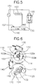
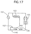
- FIGS 5, 8, 11, 14 and 17 illustrate power circuit diagrams of a microwave oven of the invention.
- An electric heater 153 for generating heat and a magnetron 155 for producing high frequency are connected in parallel with a source 151 of alternating power.
- a second switch 140 is situated between the power source 151 and the magnetron 155.
- a branch terminal between the second switch 140 and the power source 151 is used as a common terminal (COM).
- One end of a first switch 130 is a common terminal and the other end thereof contacts a normally closed terminal (NC) or a normally open terminal (NO) in the alternative.
- the normally open terminal (NO) is connected to a heater 153 and the normally closed terminal (NC) is connected to the magnetron 155.
- An oven thermistor 157 is connected between the power source 151 and the first switch 130 in order to prevent overheating of the microwave oven.
- a timer is connected in series between the power source 151 and the second switch 140 but that is not shown in the drawings.
- the timer operates the heater 153 or the magnetron 155 only for the time period set by the user and after the time period set by the user, the heater 153 and the magnetron 155 are disconnected from the power source 151.
- the operational switch operates as below.
- Figure 3 illustrates a front view of the operational switch when power controlling knob 160 is situated in the position "BROWNER".
- Figure 4 illustrates a front view of the power controlling knob 160 according to Figure 3.
- Figure 5 illustrates the power circuit diagram of the microwave oven for the position of Figure 3.
- Figure 5 illustrates the power circuit of the microwave oven when the power controlling knob 160 is situated at the step of "BROWNER". Since the contact protuberance 132 of the first switch 130 is pressed, the common terminal (COM) is connected to the normally open terminal (NO). Contact protuberance 142 of the second switch 140 is not pressed, and therefore the second switch 140 is open. Accordingly, only the heater 153 is connected to the power source 151. The magnetron 155 is not connected to the power source 151. Thus, only the heater 153 operates for the time period set by the timer. In this manner, the grill function of the microwave oven is accomplished.
- Figure 6 illustrates a front view of the operational switch when the power controlling knob 160 is situated at the position, "DEFROST".
- Figure 7 illustrates a front view of the power controlling knob 160 according to Figure 6.
- Figure 8 illustrates the diagram of the power circuit of a microwave oven for the position of Figure 6.
- the angle through which the second gear 120 has rotated in a clockwise direction is transmitted to power controlling gear 172 of the timer through a small-sized gear 170 integrally formed with the second gear 120. Then the power controlling gear 172 causes the power of magnetron 155 to become a "weak" condition. At this time, pushing piece 124 of second gear 120 does not press contact protuberance 142 of the second switch 140.
- Figure 8 is a diagram of the power circuit of the microwave oven when the power controlling knob 160 is situated in the position "DEFROST". Since the contact protuberance 132 of first switch 130 is not pressed, the common terminal COM is connected to the normally closed terminal. Also the contact protuberance 142 of the second switch 140 is not pressed, and therefore the second switch 140 is open. Accordingly, only the magnetron 155 is connected to the power source 151. The heater 153 is not connected to the power source 151. Thus, only the magnetron 155 is powered for the time period which have been set by the timer. In this manner, microwaves are generated, but at low power, so that the defrosting function of a microwave oven is accomplished.
- Figure 9 illustrates a front view of the operational switch when the power controlling knob 160 is situated at the position "COMBI".
- Figure 10 illustrates a front view of the power controlling knob 160 according to Figure 9.
- Figure 11 is a diagram of the power circuit of a microwave oven with the knob in the position of Figure 9.
- the pair of elastic pieces 103A and 103AB are engaged in a groove 112 of the guiding member 111 as shown in Figure 9.
- Stopper 113 enables the first gear 110 to rotate in a clockwise or counterclockwise direction by further departing from impeding piece 105A. Since the pushing piece 114 has rotated in a counterclockwise direction as compared to the "DEFROST" position, the pushing piece presses the contact protuberance 132 of the first switch 130. At this time, the second gear 120 rotates in a clockwise direction.
- the angle through which the second gear 120 has rotated in a clockwise direction is transmitted to the power controlling gear 172 of the timer through the small-sized gear 170 integrally formed with the second gear 120.
- the power controlling gear 172 causes the power of magnetron 155 to become a "medium” condition.
- the pushing piece 124 of second gear 120 presses contact protuberance 142 of the second switch 140.
- FIG 11 is a diagram of the power circuit of the microwave oven when the power controlling knob 160 is situated in the position "COMBI". Since the contact protuberance 132 of the first switch 130 is under pressure, the common terminal COM is connected to the normally open terminal (NO). Also the contact protuberance 142 of the second switch 140 is pressed, such that the second switch 140 is closed. Accordingly, both the magnetron 155 and the heater 153 are connected to the power source 151. That is, the magnetron 155 operates according to the power and the time period which have been set by the timer, and the heater 153 operates for the time period set by the timer. In this way, the "COMBI" function of the microwave oven, that is, a combination of both the grill function and the application of microwave power, is achieved.
- Figure 12 illustrates a front view of the operational switch when the power controlling knob 160 as shown in Figure 2 is situated at the location "MEDIUM-HIGH".
- Figure 13 illustrates a front view of the power controlling knob 160 according to Figure 12.
- Figure 14 is a diagram of the power circuit of the microwave oven with the knob 160 in the position of Figure 12.
- Figure 14 is a diagram of the power circuit of the microwave oven when the power controlling knob 160 is situated at the position "MEDIUM-HIGH". Since the contact protuberance 132 of the first switch 130 is pressed, the common terminal is connected to the normally closed terminal. Also, the contact protuberance 142 of the second switch 140 is not pressed so that the second switch 140 is open. Accordingly, the magnetron 155 is connected with the power source 151, but the heater 153 is not connected to the power source 151. That is, only the magnetron 155 operates according to the power and the time period which have been set by the timer. The heater 153 does not operate. In this manner, the microwave oven function is accomplished, at medium power.
- Figure 15 illustrates a top view of the operational switch when the power controlling knob 160 is positioned at "HIGH”.
- Figure 16 illustrates a front view of the power controlling knob 160 according to Figure 15.
- Figure 17 is a diagram of the power circuit of the microwave oven when the knob 160 is in the position of Figure 15.
- the pair of elastic pieces 103A and 103B are engaged in a groove 112 of the guiding member 111 as shown in Figure 15.
- Stopper 113 which is in contact with impeding piece 105B prohibits the first gear 110 from rotating in a counterclockwise direction. Since the pushing piece 114 has rotated in a counterclockwise direction as compared to the "MEDIUM-HIGH" position, the pushing piece 114 does not press contact protuberance 132 of the first switch 130. At this time, the second gear 120 rotates in a clockwise direction.
- the angle through which the second gear 120 has rotated in a clockwise direction is transmitted to the power controlling gear 172 of the timer through the small-sized gear 170 integrally formed with the second gear 120.
- the power controlling gear 172 thereby causes the power of the magnetron 155 to become a "strong" condition.
- the pushing piece 124 of the second gear 120 does not press the contact protuberance 142 of the second switch 140.
- Figure 17 is a diagram of the power circuit of the microwave oven when the power controlling knob 160 is situated at "HIGH". Since the contact protuberance 132 of the first switch 130 is not pressed, the common terminal is connected to the normally closed terminal. Also, the contact protuberance 142 of second switch 140 is not pressed, therefore the second switch 140 is open. Accordingly, the magnetron 155 is connected to the power source 151 but, the heater 153 is not connected to the power source 151. Thus, only the magnetron 155 operates according to the power and the time period which have been set by the timer. The heater 153 does not operate. In this way, the function of the microwave oven is performed.
- the operational switch of a microwave oven of the present invention a pair of gears and a pair of micro switches are used in order for a magnetron and an electric heater to operate. Therefore, the number of components of the operational switch for a microwave oven is reduced and thereby poor quality components are avoided from being produced, the assembling time thereof is shortened and the productivity thereof is improved.
Landscapes
- Physics & Mathematics (AREA)
- Electromagnetism (AREA)
- Engineering & Computer Science (AREA)
- Chemical & Material Sciences (AREA)
- Combustion & Propulsion (AREA)
- Mechanical Engineering (AREA)
- General Engineering & Computer Science (AREA)
- Electric Ovens (AREA)
- Constitution Of High-Frequency Heating (AREA)
- Control Of High-Frequency Heating Circuits (AREA)
Applications Claiming Priority (2)
| Application Number | Priority Date | Filing Date | Title |
|---|---|---|---|
| KR9517207 | 1995-06-23 | ||
| KR1019950017207A KR0162241B1 (ko) | 1995-06-23 | 1995-06-23 | 단기능 전자렌지의 콤비겸용 마이크로 스위치 동작장치 |
Publications (3)
| Publication Number | Publication Date |
|---|---|
| EP0750445A2 true EP0750445A2 (de) | 1996-12-27 |
| EP0750445A3 EP0750445A3 (de) | 1997-01-02 |
| EP0750445B1 EP0750445B1 (de) | 2001-12-19 |
Family
ID=19418120
Family Applications (1)
| Application Number | Title | Priority Date | Filing Date |
|---|---|---|---|
| EP96300656A Expired - Lifetime EP0750445B1 (de) | 1995-06-23 | 1996-01-30 | Bedienungsschalter für Mikrowellenofen |
Country Status (6)
| Country | Link |
|---|---|
| US (1) | US5728996A (de) |
| EP (1) | EP0750445B1 (de) |
| JP (1) | JP3795119B2 (de) |
| KR (1) | KR0162241B1 (de) |
| CN (1) | CN1131964C (de) |
| DE (1) | DE69618086T2 (de) |
Family Cites Families (6)
| Publication number | Priority date | Publication date | Assignee | Title |
|---|---|---|---|---|
| SE338797B (de) * | 1968-03-07 | 1971-09-20 | M Aberg | |
| US5134262A (en) * | 1989-05-31 | 1992-07-28 | Goldstar Co., Ltd. | Function control unit with timer for microwave oven |
| FR2670273B1 (fr) * | 1990-12-05 | 1998-03-06 | Moulinex Sa | Dispositif de commande d'un four a micro-ondes. |
| KR0135713B1 (ko) * | 1994-04-11 | 1998-04-23 | 김광호 | 전자레인지의 출력조절장치 |
| US5548104A (en) * | 1994-04-21 | 1996-08-20 | Samsung Electronics Co., Ltd. | Control apparatus of microwave oven having a magnetron and seperate heating element |
| KR200142130Y1 (ko) * | 1994-08-17 | 1999-06-01 | 전주범 | 전자렌지의 타이머장치와 출력조절장치의 설치구조 |
-
1995
- 1995-06-23 KR KR1019950017207A patent/KR0162241B1/ko not_active Expired - Fee Related
-
1996
- 1996-01-30 JP JP01467296A patent/JP3795119B2/ja not_active Expired - Fee Related
- 1996-01-30 DE DE69618086T patent/DE69618086T2/de not_active Expired - Lifetime
- 1996-01-30 EP EP96300656A patent/EP0750445B1/de not_active Expired - Lifetime
- 1996-01-31 CN CN96101474A patent/CN1131964C/zh not_active Expired - Fee Related
- 1996-01-31 US US08/594,970 patent/US5728996A/en not_active Expired - Lifetime
Also Published As
| Publication number | Publication date |
|---|---|
| JP3795119B2 (ja) | 2006-07-12 |
| KR0162241B1 (ko) | 1999-01-15 |
| CN1131964C (zh) | 2003-12-24 |
| US5728996A (en) | 1998-03-17 |
| CN1139191A (zh) | 1997-01-01 |
| JPH0914664A (ja) | 1997-01-17 |
| EP0750445A3 (de) | 1997-01-02 |
| EP0750445B1 (de) | 2001-12-19 |
| KR970002117A (ko) | 1997-01-24 |
| DE69618086T2 (de) | 2002-09-05 |
| DE69618086D1 (de) | 2002-01-31 |
Similar Documents
| Publication | Publication Date | Title |
|---|---|---|
| US4508947A (en) | Microwave ovens and methods of cooking foods | |
| JP2514010Y2 (ja) | タイマを利用した解凍装置 | |
| US4177370A (en) | Variable cooking mode selector in a microwave oven | |
| EP1058482A2 (de) | Mikrowellenofen | |
| EP0750445B1 (de) | Bedienungsschalter für Mikrowellenofen | |
| KR0135713B1 (ko) | 전자레인지의 출력조절장치 | |
| KR200142130Y1 (ko) | 전자렌지의 타이머장치와 출력조절장치의 설치구조 | |
| EP1565039A2 (de) | Mikrowellenofen | |
| KR0121986B1 (ko) | 전자렌지용 버튼식 2단 출력선택장치 | |
| JPS6030418B2 (ja) | 高周波加熱装置 | |
| JPH0112085Y2 (de) | ||
| KR100208571B1 (ko) | 전자렌지의 회동히터 | |
| JPH08322736A (ja) | オーブントースタ | |
| KR960007412Y1 (ko) | 전자렌지의 출력조절장치 | |
| JPS601511Y2 (ja) | 高周波加熱装置 | |
| JPS6322418Y2 (de) | ||
| KR20000075154A (ko) | 전자렌지의 돌입전류 방지용 타이머장치 | |
| JPS6110081Y2 (de) | ||
| JPH0935604A (ja) | 電子レンジの電子制御式タイマ | |
| JPH0228054B2 (de) | ||
| JP3634877B2 (ja) | 加熱調理器 | |
| KR880002400Y1 (ko) | 전자 오븐 렌지의 회전조리구의 축결합장치 | |
| JP2758779B2 (ja) | 加熱調理器 | |
| KR200268851Y1 (ko) | 전자레인지용 타이머 | |
| JPS5984026A (ja) | 加熱調理器 |
Legal Events
| Date | Code | Title | Description |
|---|---|---|---|
| PUAI | Public reference made under article 153(3) epc to a published international application that has entered the european phase |
Free format text: ORIGINAL CODE: 0009012 |
|
| PUAL | Search report despatched |
Free format text: ORIGINAL CODE: 0009013 |
|
| AK | Designated contracting states |
Kind code of ref document: A2 Designated state(s): DE FR GB IT NL |
|
| AK | Designated contracting states |
Kind code of ref document: A3 Designated state(s): DE FR GB IT NL |
|
| 17P | Request for examination filed |
Effective date: 19970627 |
|
| 17Q | First examination report despatched |
Effective date: 19990702 |
|
| GRAG | Despatch of communication of intention to grant |
Free format text: ORIGINAL CODE: EPIDOS AGRA |
|
| GRAG | Despatch of communication of intention to grant |
Free format text: ORIGINAL CODE: EPIDOS AGRA |
|
| GRAH | Despatch of communication of intention to grant a patent |
Free format text: ORIGINAL CODE: EPIDOS IGRA |
|
| GRAH | Despatch of communication of intention to grant a patent |
Free format text: ORIGINAL CODE: EPIDOS IGRA |
|
| GRAA | (expected) grant |
Free format text: ORIGINAL CODE: 0009210 |
|
| AK | Designated contracting states |
Kind code of ref document: B1 Designated state(s): DE FR GB IT NL |
|
| REG | Reference to a national code |
Ref country code: GB Ref legal event code: IF02 |
|
| REF | Corresponds to: |
Ref document number: 69618086 Country of ref document: DE Date of ref document: 20020131 |
|
| ET | Fr: translation filed | ||
| PLBE | No opposition filed within time limit |
Free format text: ORIGINAL CODE: 0009261 |
|
| STAA | Information on the status of an ep patent application or granted ep patent |
Free format text: STATUS: NO OPPOSITION FILED WITHIN TIME LIMIT |
|
| 26N | No opposition filed | ||
| PGFP | Annual fee paid to national office [announced via postgrant information from national office to epo] |
Ref country code: GB Payment date: 20030129 Year of fee payment: 8 |
|
| REG | Reference to a national code |
Ref country code: GB Ref legal event code: 732E |
|
| NLS | Nl: assignments of ep-patents |
Owner name: DAEWOO ELECTRONICS CORPORATION |
|
| REG | Reference to a national code |
Ref country code: FR Ref legal event code: TP |
|
| PG25 | Lapsed in a contracting state [announced via postgrant information from national office to epo] |
Ref country code: GB Free format text: LAPSE BECAUSE OF NON-PAYMENT OF DUE FEES Effective date: 20040130 |
|
| GBPC | Gb: european patent ceased through non-payment of renewal fee |
Effective date: 20040130 |
|
| PGFP | Annual fee paid to national office [announced via postgrant information from national office to epo] |
Ref country code: NL Payment date: 20050103 Year of fee payment: 10 |
|
| PG25 | Lapsed in a contracting state [announced via postgrant information from national office to epo] |
Ref country code: NL Free format text: LAPSE BECAUSE OF NON-PAYMENT OF DUE FEES Effective date: 20060801 |
|
| NLV4 | Nl: lapsed or anulled due to non-payment of the annual fee |
Effective date: 20060801 |
|
| PGFP | Annual fee paid to national office [announced via postgrant information from national office to epo] |
Ref country code: FR Payment date: 20110128 Year of fee payment: 16 Ref country code: IT Payment date: 20110126 Year of fee payment: 16 Ref country code: DE Payment date: 20110126 Year of fee payment: 16 |
|
| REG | Reference to a national code |
Ref country code: FR Ref legal event code: ST Effective date: 20120928 |
|
| PG25 | Lapsed in a contracting state [announced via postgrant information from national office to epo] |
Ref country code: DE Free format text: LAPSE BECAUSE OF NON-PAYMENT OF DUE FEES Effective date: 20120801 |
|
| REG | Reference to a national code |
Ref country code: DE Ref legal event code: R119 Ref document number: 69618086 Country of ref document: DE Effective date: 20120801 |
|
| PG25 | Lapsed in a contracting state [announced via postgrant information from national office to epo] |
Ref country code: IT Free format text: LAPSE BECAUSE OF NON-PAYMENT OF DUE FEES Effective date: 20120130 |
|
| PG25 | Lapsed in a contracting state [announced via postgrant information from national office to epo] |
Ref country code: FR Free format text: LAPSE BECAUSE OF NON-PAYMENT OF DUE FEES Effective date: 20120131 |