EP0750977B1 - Dichtungseinrichtung, insbesondere für Kunststoffverarbeitungsmaschine - Google Patents
Dichtungseinrichtung, insbesondere für Kunststoffverarbeitungsmaschine Download PDFInfo
- Publication number
- EP0750977B1 EP0750977B1 EP96109808A EP96109808A EP0750977B1 EP 0750977 B1 EP0750977 B1 EP 0750977B1 EP 96109808 A EP96109808 A EP 96109808A EP 96109808 A EP96109808 A EP 96109808A EP 0750977 B1 EP0750977 B1 EP 0750977B1
- Authority
- EP
- European Patent Office
- Prior art keywords
- duct
- lip
- sealing device
- die
- defining
- Prior art date
- Legal status (The legal status is an assumption and is not a legal conclusion. Google has not performed a legal analysis and makes no representation as to the accuracy of the status listed.)
- Expired - Lifetime
Links
- 238000007789 sealing Methods 0.000 title claims abstract description 34
- 238000001125 extrusion Methods 0.000 claims abstract description 27
- 239000000463 material Substances 0.000 claims description 18
- 239000012530 fluid Substances 0.000 claims description 4
- 229910052751 metal Inorganic materials 0.000 claims description 3
- 239000002184 metal Substances 0.000 claims description 2
- 239000011248 coating agent Substances 0.000 description 4
- 238000000576 coating method Methods 0.000 description 4
- 238000004519 manufacturing process Methods 0.000 description 3
- RYGMFSIKBFXOCR-UHFFFAOYSA-N Copper Chemical compound [Cu] RYGMFSIKBFXOCR-UHFFFAOYSA-N 0.000 description 1
- 229910000831 Steel Inorganic materials 0.000 description 1
- 230000004323 axial length Effects 0.000 description 1
- 238000006073 displacement reaction Methods 0.000 description 1
- 238000009826 distribution Methods 0.000 description 1
- 230000000694 effects Effects 0.000 description 1
- 230000005489 elastic deformation Effects 0.000 description 1
- 230000004927 fusion Effects 0.000 description 1
- 230000003100 immobilizing effect Effects 0.000 description 1
- 238000009413 insulation Methods 0.000 description 1
- 238000000034 method Methods 0.000 description 1
- 238000005121 nitriding Methods 0.000 description 1
- 230000000284 resting effect Effects 0.000 description 1
- 239000010959 steel Substances 0.000 description 1
- 230000009466 transformation Effects 0.000 description 1
- 238000011144 upstream manufacturing Methods 0.000 description 1
Images


Classifications
-
- B—PERFORMING OPERATIONS; TRANSPORTING
- B29—WORKING OF PLASTICS; WORKING OF SUBSTANCES IN A PLASTIC STATE IN GENERAL
- B29C—SHAPING OR JOINING OF PLASTICS; SHAPING OF MATERIAL IN A PLASTIC STATE, NOT OTHERWISE PROVIDED FOR; AFTER-TREATMENT OF THE SHAPED PRODUCTS, e.g. REPAIRING
- B29C48/00—Extrusion moulding, i.e. expressing the moulding material through a die or nozzle which imparts the desired form; Apparatus therefor
- B29C48/25—Component parts, details or accessories; Auxiliary operations
- B29C48/30—Extrusion nozzles or dies
- B29C48/32—Extrusion nozzles or dies with annular openings, e.g. for forming tubular articles
- B29C48/325—Extrusion nozzles or dies with annular openings, e.g. for forming tubular articles being adjustable, i.e. having adjustable exit sections
- B29C48/327—Extrusion nozzles or dies with annular openings, e.g. for forming tubular articles being adjustable, i.e. having adjustable exit sections with centering means
-
- B—PERFORMING OPERATIONS; TRANSPORTING
- B29—WORKING OF PLASTICS; WORKING OF SUBSTANCES IN A PLASTIC STATE IN GENERAL
- B29C—SHAPING OR JOINING OF PLASTICS; SHAPING OF MATERIAL IN A PLASTIC STATE, NOT OTHERWISE PROVIDED FOR; AFTER-TREATMENT OF THE SHAPED PRODUCTS, e.g. REPAIRING
- B29C48/00—Extrusion moulding, i.e. expressing the moulding material through a die or nozzle which imparts the desired form; Apparatus therefor
- B29C48/03—Extrusion moulding, i.e. expressing the moulding material through a die or nozzle which imparts the desired form; Apparatus therefor characterised by the shape of the extruded material at extrusion
- B29C48/06—Rod-shaped
-
- B—PERFORMING OPERATIONS; TRANSPORTING
- B29—WORKING OF PLASTICS; WORKING OF SUBSTANCES IN A PLASTIC STATE IN GENERAL
- B29C—SHAPING OR JOINING OF PLASTICS; SHAPING OF MATERIAL IN A PLASTIC STATE, NOT OTHERWISE PROVIDED FOR; AFTER-TREATMENT OF THE SHAPED PRODUCTS, e.g. REPAIRING
- B29C48/00—Extrusion moulding, i.e. expressing the moulding material through a die or nozzle which imparts the desired form; Apparatus therefor
- B29C48/15—Extrusion moulding, i.e. expressing the moulding material through a die or nozzle which imparts the desired form; Apparatus therefor incorporating preformed parts or layers, e.g. extrusion moulding around inserts
-
- B—PERFORMING OPERATIONS; TRANSPORTING
- B29—WORKING OF PLASTICS; WORKING OF SUBSTANCES IN A PLASTIC STATE IN GENERAL
- B29C—SHAPING OR JOINING OF PLASTICS; SHAPING OF MATERIAL IN A PLASTIC STATE, NOT OTHERWISE PROVIDED FOR; AFTER-TREATMENT OF THE SHAPED PRODUCTS, e.g. REPAIRING
- B29C48/00—Extrusion moulding, i.e. expressing the moulding material through a die or nozzle which imparts the desired form; Apparatus therefor
- B29C48/25—Component parts, details or accessories; Auxiliary operations
- B29C48/254—Sealing means
-
- B—PERFORMING OPERATIONS; TRANSPORTING
- B29—WORKING OF PLASTICS; WORKING OF SUBSTANCES IN A PLASTIC STATE IN GENERAL
- B29C—SHAPING OR JOINING OF PLASTICS; SHAPING OF MATERIAL IN A PLASTIC STATE, NOT OTHERWISE PROVIDED FOR; AFTER-TREATMENT OF THE SHAPED PRODUCTS, e.g. REPAIRING
- B29C48/00—Extrusion moulding, i.e. expressing the moulding material through a die or nozzle which imparts the desired form; Apparatus therefor
- B29C48/03—Extrusion moulding, i.e. expressing the moulding material through a die or nozzle which imparts the desired form; Apparatus therefor characterised by the shape of the extruded material at extrusion
Definitions
- the invention relates to a sealing device, especially for material processing machine plastic.
- the invention relates to a device for sealing between two mechanical elements intended to convey a flow of plastic material in fusion under strong pressure.
- a typical example where sealing problems occur pose in this area of technique is that of extrusion dies in which the temperature of the molten plastic can rise to 500 ° C or more under pressure which can sometimes reach 1000 bars.
- This sealing device includes a cylindrical sealing ring having at one of its ends a frustoconical edge inclined in the direction flow of the material so as not to create obstacle likely to obstruct this flow.
- the flange frustoconical has a cylindrical outer surface which is resting against the interior surface of the first pipe under prestress due to dimensional tolerances of the outer surface of said ledge and interior surface of the first pipe.
- the main aim of the invention is therefore to provide a sealing device, especially for a transformation of plastic material, which can be manufactured with relatively wide tolerances and allowing in some extent a displacement of the elements one by relative to each other to ensure certain settings or adjustments.
- the invention therefore relates to a sealing device for sealing between two pipes intended to convey a fluid, especially a flow of plastic material at high temperature and under high pressure, this device comprising a first part of general shape cylindrical and at least partially defining the first pipe and a second piece also shaped general cylindrical and defining at least in part the second pipe, said second part being inserted in said first pipeline, characterized in that said second part comprises, at least one of these ends, an annular lip protruding from its surface external cylindrical and connected at this end by a thinned annular zone, said lip having a cylindrical outer surface which bears against the inner surface of said first part under a prestress due to dimensional tolerances of said outer surface of said lip and said surface interior of said first cylindrical part.
- Figure 1 shows a first example of application of the sealing device according to the invention to a head plastic extrusion 1 of which only a part has been shown in the drawing.
- the body 2 of this head extrusion has a passage 3 of cylindrical section, through which the molten plastic is brought under high pressure.
- a wire guide 4 ending with a conical part 5 is placed coaxially in line 3. It is crossed by a metal wire 6 to be coated with material plastic.
- material plastic For example, it may be copper wire which must be sheathed with insulation.
- the body 2 of the extrusion head 1 comprises a end piece 7 externally threaded and on which a nut 8. The latter is used to hold a die in place 9 placed in the pipe 3 of the body 2 and on which the sealing device is materialized according to the invention.
- the die 9 has a generally cylindrical shape and defines a central passage 10 comprising a part taper 11 with the same taper as that of the thread guide 4. This the latter is placed in line 9 so that there define a flow channel 12 of the plastic to which the calibrated orifice 13 of the sector 9.
- the envelope of the external surface of the die 9 is cylindrical.
- This outer surface has a annular groove 14 whose axial dimension (otherwise says its width) spans a significant part of the total axial dimension of the die so that this is clear in this area of the surface interior of the body 2.
- this groove 13 defines, on the one hand downstream from the material flow plastic, an outer surface 15 projecting slightly of the nozzle 7 of the body 2 and, on the other hand upstream, a lip 16 which constitutes the main element of the device sealing according to the invention.
- the profile of the lip 16 appears on a scale enlarged in Figure 2. We see that in the present example, it has a triangular shape in radial section connected to the body of the die 9 by an annular zone connection 17 generally thinned and intended to deform within the limit of its elastic deformation during the establishment of the sector in line 3 and also while the plastic is flowing in the flow channel 12.
- the lip itself has externally a cylindrical surface 18 whose diameter is slightly higher than that of the die body.
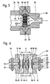
- Figure 3 shows an axial sectional view of a part 1A of an extrusion head (which will be designated by the "extrusion head 1A") in which is incorporated a particularly advantageous characteristic of the invention.
- This extrusion head comprises a body 2 and a wire guide 4 identical to those provided in the head extrusion shown in Figure 1.
- this extrusion head 1A has a die 9A whose shape is slightly different from that of the sector 9 represented in FIG. 1. Indeed, its external surface does not present, besides the lip annular 16, no other roughness, but on the contrary a cylindrical surface 15A of constant diameter and slightly lower than that of passage 3 of the head body extrusion 1A.
- nut 8A serving not only when the 9A sector is immobilized in the pipe 3, but also to the radial adjustment thereof.
- cylindrical skirt 19 of this nut 8A has two radial threaded holes 20, preferably aligned with each other. These holes are intended for receive adjustment screws 21.
- this arrangement makes it possible to tilt the axis of the die 9A relative to that of passage 3 and therefore of the wire guide 1 in acting on the adjusting screws 21.
- This inclination will along with an asymmetric deformation of the lip 16 of the die 9A whose connection area 17 is deformed slightly.
- Part 1B of the extrusion head (which will be hereinafter referred to as "extrusion head” 1B) according to the embodiment of FIG. 4 comprises a body 2B formed of a simple tubular piece. In the pipeline cylindrical 3B of this body 2B is inserted a die holder 23 serving as an intermediate part for mounting a die 9B proper.
- the die holder 23 is a tubular piece on one the ends of which the annular lip is formed 16 of the sealing device according to the invention. To his other end, the die holder 23 is provided with a flange fixing 24 by means of which it is fixed on the body 2B using screws 25 axially oriented. Enter here annular lip 16 and flange 24, this die holder has an outer surface 26 of uniform diameter significantly lower than that of the passage 3B of the body 2B.
- the die holder 23 has a bore whose rear part 27 is conical and extends the inner surface of the lip 16. On this part conical 27 connects to the front a cylindrical part right 28 intended to receive the die 9B.
- This has an internal bore with a tapered rear part 29 which in turn is connected to the conical part 27 of the die holder 23.
- the front part of this bore constitutes the calibrated orifice 13 of the head extrusion.
- the sector has at the front a support flange 30 intended to be applied against a radial shoulder 31 formed in the die holder 23 to height of flange 24. It is threaded internally and receives a fixing nut 32 immobilizing the die 9B in the die holder 23.
- the axis of the die 9B can be inclined relative to that of passage 3B by interposing a shim 33 between the flange 24 and the body 2B at a determined location on the periphery of this flange.
- the sealing device according to the invention according to the embodiment of Figure 5 is used in the junction of two tubular mechanical parts 34 and 35 intended to convey a flow of plastic material from a pipe of a given section to a section pipe equal or lower.
- Each of the flanges also has a shoulder radial 41, 42 against which a plate rests orifices 43 to make the flow profile of the plastic downstream of part 35.
- This plate therefore constitutes by its orifices 43a a second pipeline formed by each of the defined passages by parts 34 and 35 respectively.
- the orifice plate 43 is thus inserted into each of the first pipes 44 and 45 and comprises two annular lips 16 extending respectively axially from its radial faces and supported against the respective interior surfaces of lines 44 and 45 of parts 34 and 35. These are the lips which seal the junction and this with all the more effective as the pressure of the material plastic in the pipes is higher. This pressure also ensures the support of flanges 36 and 37 against the half-collars 38 and 39.
- Figure 6 shows another application of the sealing device according to the invention in which it is to seal between two pieces of connection 46 and 47 forming a junction in two pipes parallel and able to convey plastic material to high temperature and under high pressure.
- Connection pieces 46 and 47 each define first parallel pipes, resp. 48, 49 and 50, 51 and each have a fixing flange 52 provided with holes 53 for the passage of clamping screws 54.
- a centering pin 55 inserted in axial holes 56 correspondents of these connection parts.
- the sealing device in this case comprises two sockets 57 and 58 inserted in pairs respectively of aligned pipes 48, 49 and 50, 51 and defining each a second line 58a and 58b.
- Each of these sockets comprises at each of its ends a annular lip 16 with the same profile as the annular lip shown in Figure 2.
- Each socket 57, 58 is in additionally provided with an annular rib 59 by means of which it is positioned axially, this rib being taken between the opposite faces of the flanges 52 during of the assembly of the assembly.
Landscapes
- Engineering & Computer Science (AREA)
- Mechanical Engineering (AREA)
- Manufacturing & Machinery (AREA)
- Extrusion Moulding Of Plastics Or The Like (AREA)
- Processing And Handling Of Plastics And Other Materials For Molding In General (AREA)
Claims (7)
- Dichtungsvorrichtung zur Sicherstellung einer dichten Verbindung zwischen zwei Rohrleitungen (3 und 11, 13; 3B und 11, 13; 48 bis 51 und 57a, 58a), die dazu bestimmt sind, ein Fluid, insbesondere eine Kunststoffströmung, zu transportieren, wobei diese Vorrichtung ein erstes Teil (2; 2B; 46, 47) mit allgemeiner zylindrischer Form, das wenigstens zum Teil die erste Rohrleitung (3; 3B; 48 bis 51) definiert, und ein zweites Teil (9; 9B, 23; 57, 58), das ebenfalls eine allgemeine zylindrische Form besitzt und wenigstens zum Teil die zweite Rohrleitung (11, 13; 57a, 58a) definiert, umfaßt, wobei das zweite Teil (9; 23, 9B; 57, 58) in die erste Rohrleitung (3; 3B; 48 bis 51) eingeschoben ist und an wenigstens einem seiner Enden eine ringförmige metallische Lippe (16) aufweist, die über ihre äußere zylindrische Fläche vorsteht und eine zylindrische äußere Oberfläche (18) aufweist, die sich an der inneren Oberfläche des ersten Teils (2; 2B; 46, 47) unter einer Vorspannung aufgrund der Abmessungstoleranzen der äußeren Oberfläche (18) der Lippe (16) und der inneren Oberfläche des ersten zylindrischen Teils (2; 2B; 46, 47) abstützt,
dadurch gekennzeichnet, daß
die ringförmige Lippe (16) mit dem Ende des zweiten Teils (9; 23, 9B; 57, 58) durch eine in bezug auf die Lippe (16) und den Körper des zweiten Teils (9; 23, 9B; 57, 58) eingeschnürte ringförmige Zone (17) verbunden ist. - Dichtungsvorrichtung nach Anspruch 1, dadurch gekennzeichnet, daß die innere Oberfläche der Lippe (16) kegelstumpfförmig ist.
- Dichtungsvorrichtung nach Anspruch 2, dadurch gekennzeichnet, daß die kegelstumpfförmige innere Oberfläche der Lippe (16) durch dieselbe kegelstumpfförmige Oberfläche, die an der Verbindungszone (17) bzw. dem zweiten zylindrischen Teil (9; 23, 9B) vorgesehen ist, verlängert ist.
- Dichtungsvorrichtung nach einem der Ansprüche 1 und 2, dadurch gekennzeichnet, daß die zweite Rohrleitung (57a, 58a) in einer Hülse (57, 58) ausgebildet ist, die in die erste Rohrleitung (48 bis 51) eingeschoben ist.
- Dichtungsvorrichtung zur Sicherstellung einer dichten Verbindung zwischen zwei Rohrleitungen (44, 45 und 43a), die dazu bestimmt sind, ein Fluid, insbesondere eine Kunststoffströmung, von einem Rohr mit gegebenem Querschnitt zu einem Rohr mit gleichem oder kleinerem Querschnitt zu transportieren, wobei diese Vorrichtung ein erstes Teil (34, 35) mit im allgemeinen zylindrischer Form, das wenigstens zum Teil die erste Rohrleitung (44, 45) definiert, und ein zweites Teil (43), das ebenfalls eine im allgemeinen zylindrische Form besitzt und wenigstens zum Teil die zweite Rohrleitung (43a) definiert, umfaßt, wobei das zweite Teil in die erste Rohrleitung (44, 45) eingeschoben ist, dadurch gekennzeichnet, daß die zweite Rohrleitung (43a) in einer Platte mit Öffnungen (43) ausgebildet ist, die in der ersten Rohrleitung (44 oder 45) angeordnet sind, wobei die Platte mit Öffnungen zwei ringförmige Lippen (16) aufweist, die sich von ihren radialen Flächen jeweils axial erstrecken und sich an den jeweiligen inneren Oberflächen der Rohrleitungen (44, 45) der Teile (34, 35) abstützen.
- Kunststoff-Extruderkopf, der eine Dichtungsvorrichtung nach einem der Ansprüche 1 bis 3 umfaßt, dadurch gekennzeichnet, daß die erste Rohrleitung (3; 3B) im Körper (2; 2B) des Kopfes (1, 1B) ausgebildet ist und die zweite Rohrleitung im Mundstück dieses Extruderkopfes ausgebildet ist, wobei die Dichtungsvorrichtung zwischen dem Körper und dem Mundstück vorgesehen ist.
- Extruderkopf nach Anspruch 6, dadurch gekennzeichnet, daß er Mittel (8A, 20, 21; 33) umfaßt, um die Öffnung des Mundstücks (9; 9A; 9B) in bezug auf die Achse der ersten Rohrleitung (3; 3B) zu versetzen, wobei die Versetzungsmittel so beschaffen sind, daß sie die Verbindungszone (17) zwischen der Lippe (16) und dem Mundstück verformen.
Applications Claiming Priority (2)
| Application Number | Priority Date | Filing Date | Title |
|---|---|---|---|
| FR9507845A FR2736134B1 (fr) | 1995-06-29 | 1995-06-29 | Dispositif d'etancheite, notamment pour machine de transformation de matiere plastique |
| FR9507845 | 1995-06-29 |
Publications (2)
| Publication Number | Publication Date |
|---|---|
| EP0750977A1 EP0750977A1 (de) | 1997-01-02 |
| EP0750977B1 true EP0750977B1 (de) | 2002-05-29 |
Family
ID=9480519
Family Applications (1)
| Application Number | Title | Priority Date | Filing Date |
|---|---|---|---|
| EP96109808A Expired - Lifetime EP0750977B1 (de) | 1995-06-29 | 1996-06-19 | Dichtungseinrichtung, insbesondere für Kunststoffverarbeitungsmaschine |
Country Status (5)
| Country | Link |
|---|---|
| US (1) | US5690971A (de) |
| EP (1) | EP0750977B1 (de) |
| AT (1) | ATE218093T1 (de) |
| DE (1) | DE69621379T2 (de) |
| FR (1) | FR2736134B1 (de) |
Families Citing this family (13)
| Publication number | Priority date | Publication date | Assignee | Title |
|---|---|---|---|---|
| US5904657A (en) * | 1997-02-26 | 1999-05-18 | Unsworth; John D. | System for guiding devices in body lumens |
| US6382944B1 (en) * | 1998-11-10 | 2002-05-07 | Guill Tool & Engineering Co., Inc. | Universally mounted adjustable die |
| US6902388B2 (en) * | 1998-11-10 | 2005-06-07 | Guill Tool And Engineering Co., Inc. | Pivotally adjustable die |
| JP4089113B2 (ja) * | 1999-12-28 | 2008-05-28 | 株式会社Ihi | 薄膜作成装置 |
| ES2334105T3 (es) * | 2001-12-21 | 2010-03-05 | Prysmian S.P.A. | Procedimiento y cabezal de extrusion para la extrusion de un material polimerico. |
| US6915647B2 (en) * | 2003-05-21 | 2005-07-12 | Hoshizaki Denki Kabushiki Kaisha | Abnormality detecting device of auger-type ice making machine and abnormality detecting method thereof |
| BRPI0520073B1 (pt) | 2005-04-27 | 2017-06-27 | Pirelli Tyre S.P.A | Method and apparatus for extruding a polymeric material in the manufacture of a tire, and method for manufacturing a tire |
| DE102009058361B3 (de) * | 2009-12-15 | 2011-06-01 | Gross, Heinz, Dr.-Ing. | Düse |
| JP5448935B2 (ja) * | 2010-03-01 | 2014-03-19 | Tmtマシナリー株式会社 | 紡糸パック |
| DE102011118719A1 (de) * | 2011-11-16 | 2013-05-16 | Brabender Gmbh & Co.Kg | Vorrichtung zum Extrudieren eines medizinischen Instruments, das in einen menschlichen oder tierischen Körper einführbar ist |
| DE102013109495B3 (de) * | 2013-08-30 | 2014-08-14 | Harald Feuerherm | Extrusionswerkzeug zur Erzeugung schlauchförmiger Vorformlinge |
| IT201600128201A1 (it) * | 2016-12-19 | 2018-06-19 | Lemur S R L | Apparato e metodo per rivestire un'anima filiforme e articolo filiforme cosi' ottenuto |
| US11312055B2 (en) | 2018-10-01 | 2022-04-26 | Homar Cisneros | Method of adjusting a crosshead extruder die retaining assembly |
Family Cites Families (16)
| Publication number | Priority date | Publication date | Assignee | Title |
|---|---|---|---|---|
| US1302778A (en) * | 1918-07-31 | 1919-05-06 | Stone J & Co Ltd | Expansion-joint. |
| US2185701A (en) * | 1937-01-23 | 1940-01-02 | Anaconda Wire & Cable Co | Extruding apparatus |
| US2943351A (en) * | 1956-05-08 | 1960-07-05 | Western Electric Co | Methods of and apparatus for extruding plastic materials |
| US3222721A (en) * | 1962-06-25 | 1965-12-14 | Anaconda Wire & Cable Co | Dual extrusion apparatus |
| US3752614A (en) * | 1971-02-02 | 1973-08-14 | Bremertron Kl Corp | Adjustable extrusion head |
| US3947173A (en) * | 1972-09-13 | 1976-03-30 | Western Electric Company, Inc. | Apparatus for extruding concentric plastic sheaths |
| AT320265B (de) * | 1972-09-26 | 1975-02-10 | Cincinnati Milacron Ges M B H | Spritzkopf zur Herstellung von Schlauchfolien aus thermoplastischem Kunststoff |
| US4260351A (en) * | 1975-11-04 | 1981-04-07 | Hitachi Cables, Ltd. | Apparatus for producing foamed plastic insulated wires |
| NO161142C (no) * | 1978-03-13 | 1989-07-05 | Wavin Bv | Roerdel med en muffeende og et i denne anordnet tetningsorgan som er understoettet av en stoettering. |
| US4473230A (en) * | 1984-02-10 | 1984-09-25 | Gary Tool Company | Tension hanger embodying fire resistant sealing means |
| FR2573341B1 (fr) * | 1984-11-21 | 1987-01-30 | Pirelli Treficable | Tete d'extrusion rotative, notamment pour la fabrication de joncs a rainures helicoidales pour fibres optiques |
| US4641841A (en) * | 1985-08-26 | 1987-02-10 | Hughes Tool Company | Metal seal for a tubular connection |
| US4781053A (en) * | 1986-03-05 | 1988-11-01 | Stewart Charles L | Indirect extrusion process and machinery therefor |
| CH678239A5 (de) * | 1987-05-29 | 1991-08-15 | Maillefer Sa | |
| US5151147A (en) * | 1990-08-17 | 1992-09-29 | Reynolds Metals Company | Coated article production system |
| US5443589A (en) * | 1993-12-30 | 1995-08-22 | Brandon; Ronald E. | Steam turbine bell seals |
-
1995
- 1995-06-29 FR FR9507845A patent/FR2736134B1/fr not_active Expired - Fee Related
-
1996
- 1996-06-19 EP EP96109808A patent/EP0750977B1/de not_active Expired - Lifetime
- 1996-06-19 AT AT96109808T patent/ATE218093T1/de not_active IP Right Cessation
- 1996-06-19 DE DE69621379T patent/DE69621379T2/de not_active Expired - Fee Related
- 1996-06-26 US US08/670,431 patent/US5690971A/en not_active Expired - Lifetime
Also Published As
| Publication number | Publication date |
|---|---|
| FR2736134B1 (fr) | 1997-08-22 |
| FR2736134A1 (fr) | 1997-01-03 |
| ATE218093T1 (de) | 2002-06-15 |
| DE69621379D1 (de) | 2002-07-04 |
| DE69621379T2 (de) | 2003-02-13 |
| US5690971A (en) | 1997-11-25 |
| EP0750977A1 (de) | 1997-01-02 |
Similar Documents
| Publication | Publication Date | Title |
|---|---|---|
| EP0750977B1 (de) | Dichtungseinrichtung, insbesondere für Kunststoffverarbeitungsmaschine | |
| EP0139712B1 (de) | Verfahren zum verbinden mehrerer teile, insbesondere teilen von rohrverbindungsstücken | |
| FR2769067A1 (fr) | Assemblage visse avec anneau de support | |
| FR2616862A1 (fr) | Dispositif d'accouplement debrayable a serrage hydraulique | |
| FR2781274A1 (fr) | Raccord pour tubes, comprenant un troncon de raccordement conforme a une extremite d'un tube | |
| KR20200031138A (ko) | 접합 연결부를 구비한 파이프 장치 | |
| FR2789610A1 (fr) | Procede de fabrication d'une rampe commune | |
| FR2800151A1 (fr) | Raccord a tubes comportant un troncon de raccord forme sur le tube | |
| EP0360690B1 (de) | Kupplungs- und Dichtvorrichtung mit Metallippe | |
| FR2690966A3 (fr) | Outil destiné à désaérer des systèmes hydrauliques. | |
| FR2568327A1 (fr) | Dispositif de fixation sur une paroi du conduit de gainage d'une commande a cable | |
| EP0187608B1 (de) | Schnellverbindung für unter Druck stehende Flüssigkeitssysteme in denen der Druck 150 bar erreichen kann | |
| FR2677688A1 (fr) | Tube de raccordement pour cuvette de toilettes. | |
| FR2775753A1 (fr) | Collier de serrage pour tubes a connecter, en particulier tubes d'echappement | |
| EP0581678B1 (de) | Schlauch mit radialer Spannvorrichtung zum Verbinden mit einem Rohrende; Schlauchverbindung mit diesem Schlauch | |
| BE1015282A3 (fr) | Vanne de distribution pour installations de chauffage avec corps en matiere plastique. | |
| EP0469999B1 (de) | Verfahren zur dichten Verbindung und entsprechende dichte Verbindung | |
| EP0233827B1 (de) | Vorrichtung zum Befestigen eines Ventils an einem Rohr und Verfahren zu dessen Montage | |
| FR2489472A1 (fr) | Dispositif de securite pour empecher le deplacement axial de liaisons par manchon de conduits tubulaires en matiere synthetique | |
| FR2888307A1 (fr) | Raccord pour robinetterie. | |
| EP0440566B1 (de) | Muffenrohr aus Kunststoff sowie Herstellungsverfahren dafür | |
| EP1070902A2 (de) | Abzweigrohr und Verfahren zu dessen Herstellung | |
| EP0766034A1 (de) | Vorrichtung zum Verbinden von rohrförmigen Elementen mit Ventilgehäusen | |
| FR2785359A1 (fr) | Collier de prise en charge a bague anti-fluage de joint et procede de fabrication | |
| FR2878306A1 (fr) | Procede de fabrication d'un element d'etancheite, element d'etancheite et embase de raccordement correspondants |
Legal Events
| Date | Code | Title | Description |
|---|---|---|---|
| PUAI | Public reference made under article 153(3) epc to a published international application that has entered the european phase |
Free format text: ORIGINAL CODE: 0009012 |
|
| AK | Designated contracting states |
Kind code of ref document: A1 Designated state(s): AT CH DE FI IT LI |
|
| 17P | Request for examination filed |
Effective date: 19970702 |
|
| 17Q | First examination report despatched |
Effective date: 19980623 |
|
| GRAG | Despatch of communication of intention to grant |
Free format text: ORIGINAL CODE: EPIDOS AGRA |
|
| GRAG | Despatch of communication of intention to grant |
Free format text: ORIGINAL CODE: EPIDOS AGRA |
|
| GRAH | Despatch of communication of intention to grant a patent |
Free format text: ORIGINAL CODE: EPIDOS IGRA |
|
| RAP1 | Party data changed (applicant data changed or rights of an application transferred) |
Owner name: SWISSCAB S.A. |
|
| GRAH | Despatch of communication of intention to grant a patent |
Free format text: ORIGINAL CODE: EPIDOS IGRA |
|
| GRAA | (expected) grant |
Free format text: ORIGINAL CODE: 0009210 |
|
| AK | Designated contracting states |
Kind code of ref document: B1 Designated state(s): AT CH DE FI IT LI |
|
| PG25 | Lapsed in a contracting state [announced via postgrant information from national office to epo] |
Ref country code: IT Free format text: LAPSE BECAUSE OF FAILURE TO SUBMIT A TRANSLATION OF THE DESCRIPTION OR TO PAY THE FEE WITHIN THE PRESCRIBED TIME-LIMIT;WARNING: LAPSES OF ITALIAN PATENTS WITH EFFECTIVE DATE BEFORE 2007 MAY HAVE OCCURRED AT ANY TIME BEFORE 2007. THE CORRECT EFFECTIVE DATE MAY BE DIFFERENT FROM THE ONE RECORDED. Effective date: 20020529 Ref country code: FI Free format text: LAPSE BECAUSE OF FAILURE TO SUBMIT A TRANSLATION OF THE DESCRIPTION OR TO PAY THE FEE WITHIN THE PRESCRIBED TIME-LIMIT Effective date: 20020529 |
|
| REF | Corresponds to: |
Ref document number: 218093 Country of ref document: AT Date of ref document: 20020615 Kind code of ref document: T |
|
| REG | Reference to a national code |
Ref country code: CH Ref legal event code: EP |
|
| REF | Corresponds to: |
Ref document number: 69621379 Country of ref document: DE Date of ref document: 20020704 |
|
| PLBE | No opposition filed within time limit |
Free format text: ORIGINAL CODE: 0009261 |
|
| STAA | Information on the status of an ep patent application or granted ep patent |
Free format text: STATUS: NO OPPOSITION FILED WITHIN TIME LIMIT |
|
| REG | Reference to a national code |
Ref country code: CH Ref legal event code: PUE Owner name: APSWISS TECH S.A. Free format text: SWISSCAB S.A.#RUE DE L'INDUSTRIE 5 ET CHEMIN DE LA PETITE AMERIQUE 2#1462 YVONAND (CH) -TRANSFER TO- APSWISS TECH S.A.#5, RUE DE L'INDUSTRIE#1462 YVONAND (CH) Ref country code: CH Ref legal event code: NV Representative=s name: CABINET ROLAND NITHARDT CONSEILS EN PROPRIETE INDU |
|
| 26N | No opposition filed |
Effective date: 20030303 |
|
| PGFP | Annual fee paid to national office [announced via postgrant information from national office to epo] |
Ref country code: AT Payment date: 20090629 Year of fee payment: 14 |
|
| PGFP | Annual fee paid to national office [announced via postgrant information from national office to epo] |
Ref country code: DE Payment date: 20090824 Year of fee payment: 14 Ref country code: CH Payment date: 20090917 Year of fee payment: 14 |
|
| REG | Reference to a national code |
Ref country code: CH Ref legal event code: PL |
|
| PG25 | Lapsed in a contracting state [announced via postgrant information from national office to epo] |
Ref country code: DE Free format text: LAPSE BECAUSE OF NON-PAYMENT OF DUE FEES Effective date: 20110101 Ref country code: LI Free format text: LAPSE BECAUSE OF NON-PAYMENT OF DUE FEES Effective date: 20100630 Ref country code: CH Free format text: LAPSE BECAUSE OF NON-PAYMENT OF DUE FEES Effective date: 20100630 |
|
| PG25 | Lapsed in a contracting state [announced via postgrant information from national office to epo] |
Ref country code: AT Free format text: LAPSE BECAUSE OF NON-PAYMENT OF DUE FEES Effective date: 20100619 |