EP0751004A1 - Mechanismus zur Befestigung einer Bandkassette für einen Drucker - Google Patents
Mechanismus zur Befestigung einer Bandkassette für einen Drucker Download PDFInfo
- Publication number
- EP0751004A1 EP0751004A1 EP96110531A EP96110531A EP0751004A1 EP 0751004 A1 EP0751004 A1 EP 0751004A1 EP 96110531 A EP96110531 A EP 96110531A EP 96110531 A EP96110531 A EP 96110531A EP 0751004 A1 EP0751004 A1 EP 0751004A1
- Authority
- EP
- European Patent Office
- Prior art keywords
- engaging
- ribbon cassette
- engaging pin
- hooks
- carrier frame
- Prior art date
- Legal status (The legal status is an assumption and is not a legal conclusion. Google has not performed a legal analysis and makes no representation as to the accuracy of the status listed.)
- Withdrawn
Links
- 230000004048 modification Effects 0.000 description 1
- 238000012986 modification Methods 0.000 description 1
Images




Classifications
-
- B—PERFORMING OPERATIONS; TRANSPORTING
- B41—PRINTING; LINING MACHINES; TYPEWRITERS; STAMPS
- B41J—TYPEWRITERS; SELECTIVE PRINTING MECHANISMS, i.e. MECHANISMS PRINTING OTHERWISE THAN FROM A FORME; CORRECTION OF TYPOGRAPHICAL ERRORS
- B41J35/00—Other apparatus or arrangements associated with, or incorporated in, ink-ribbon mechanisms
- B41J35/28—Detachable carriers or holders for ink-ribbon mechanisms
Definitions
- the present invention relates to a ribbon cassette attaching/detaching mechanism of a printer.
- an engaging hook 3a is formed on a carrier frame 3, and this engaging hook 3a engages with an engaging pin 7a of a ribbon cassette 7, as shown in Fig. 7A.
- the ribbon cassette 7 When disengaging the ribbon cassette 7, as shown in Figs. 7B and 7C, the ribbon cassette 7 is rotated clockwise about its engaging pin 7a as the center, is moved to the left, and is pulled upward, thereby removing the ribbon cassette 7. However, before the engaging pin 7a is not disengaged from the engaging hook 3a of the carrier frame 3, if the ribbon cassette 7 is forcively lifted upward or is further rotated clockwise from the state shown in Fig. 7D, the engaging pin 7a or the engaging hook 3a may be broken.
- a ribbon cassette attaching/detaching mechanism comprising a carrier frame having engaging hooks, a ribbon cassette having an engaging pin, the ribbon cassette being fixed to the carrier frame when the engaging pin engages with the engaging hooks, and being removed from the carrier frame when the ribbon cassette is pivoted about the engaging pin as a center from a state of being fixed to the carrier frame to disengage the engaging pin from the engaging hooks, and projecting members which come into contact with an end portion of the ribbon cassette on an engaging pin side, when the ribbon cassette is pivoted through a predetermined angle about the engaging pin as the center, thereby moving the engaging pin away from the engaging hooks.
- Fig. 1 shows an ink ribbon cassette attaching/detaching mechanism according to the first embodiment of the present invention.
- a platen 101 opposes a print head 102 through a recording sheet.
- the print head 102 performs printing on the recording sheet on the platen 101 with an impact generated by a wire in the head 102 through an ink ribbon.
- the print head 102 is fixed to a carrier frame 103.
- the carrier frame 103 is supported by a guide shaft 104 and a main stay 105 and can be slid by a timing belt 106 in the longitudinal direction of the guide shaft 104.
- a ribbon cassette 107 is detachably mounted on the carrier frame 103.
- a pair of opposing projecting segments 107b are formed on the rear end of the ribbon cassette 107 on the main stay 105 side, and an engaging pin 107a parallel to the main stay 105 is provided between the distal end portions of the projecting segments 107b.
- Curved surfaces 107c of the distal ends of the projecting segments 107b form arcuated surfaces each having a predetermined diameter.
- Fig. 2 shows the engaging portion of the ribbon cassette 107 and the carrier frame 103.
- a pair of engaging hooks 103a are integrally formed on the carrier frame 103 to correspond to the engaging pin 107a of the ribbon cassette 107 such that they oppose the ribbon cassette 107.
- the engaging hooks 103a hook the engaging pin 107a serving as the pivot shaft.
- inclined projections 103b are formed integrally with the engaging hooks 103a.
- Each inclined projection 103b is formed to be sharply lowered toward the engaging portion of the engaging pin 107a and the corresponding engaging hook 103a.
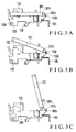
- Fig. 3A shows a state wherein the ribbon cassette 107 is completely mounted on the carrier frame 103
- Fig. 4A shows part of Fig. 3A.
- the ribbon cassette 107 is pivoted clockwise about the engaging pin 107a as the center to obtain a state shown in Fig. 3B.
- a state shown in Fig. 4C is obtained through a state shown in Fig. 4B.
- the curved surfaces 107c of the distal ends of the ribbon cassette 107 come into contact with the inclined projections 103b.
- the curved surfaces 107c of the distal ends of the projecting segments 107b slide on the inclined surfaces of the inclined projections 103b to move the engaging pin 107a supported by the projecting segments 107b.
- the inclined surface of each inclined projection 103b is formed to be sharply lowered toward the engaging portion of the engaging pin 107a and the corresponding engaging hook 103a
- the engaging pin 107a smoothly slides on the curved surfaces 107c of the distal ends of the projecting segments 107b along the inclined surfaces of the inclined projections 103b to naturally disengage from the engaging hooks 103a as it is pushed outward.
- FIG. 3C shows a state wherein the ribbon cassette 107 is kept disengaged from the carrier frame 103.
- the engaging pin 107a can be naturally disengaged from the engaging hooks 103a only by pivoting the ribbon cassette 107 through almost 90°. Even if the ribbon cassette 107 is rotated through more than 90°, as the engaging pin 107a has already been disengaged from the engaging hooks 103a, an excessive force will not act on the engaging pin 107a or the engaging hooks 103a, so that they will not be broken.
- Fig. 5 shows the second embodiment of the present invention.
- the engaging hooks 103a are arranged between (on the inner sides of) the projecting segments 107b.
- engaging hooks 203a of a carrier frame 203 are arranged on the outer sides of projecting segments 207b of a ribbon cassette 207.
- Engaging pins 207a which are to be hooked by the engaging hooks 203a are cantilevered to project to the outer sides of the projecting segments 207b.
- Reference numeral 201 denotes a platen; 202, a printer head; 204, a guide shaft; 205, a main stay; and 206, a timing belt, respectively.
- Inclined projections 203b are formed integrally with the carrier frame 203 on sides opposite to the positions of the inclined projections 103b of Fig. 1, i.e., on the inner sides of the engaging hooks 203a to correspond to curved surfaces 207c of the distal ends of the projecting segments 207b.
- cylindrical projections 303b integrally formed on engaging hooks 303a may be used in place of the inclined projections. More specifically, as far as the projections have inclined surfaces (cylindrical surfaces if the projections are cylindrical projections) which are sharply lowered toward the engaging pin engaging with the engaging hooks, the rear end portion of the ribbon cassette slides on these inclined surfaces, so that the engaging pin can be removed smoothly.
- the projections such as inclined projections or cylindrical projections may not be formed on the engaging hooks but be fixed on the carrier frame directly.
- the carrier frame can be prevented from being broken, and the ribbon cassette can be removed easily.
Landscapes
- Impression-Transfer Materials And Handling Thereof (AREA)
Applications Claiming Priority (2)
| Application Number | Priority Date | Filing Date | Title |
|---|---|---|---|
| JP163234/95 | 1995-06-29 | ||
| JP7163234A JP2708020B2 (ja) | 1995-06-29 | 1995-06-29 | リボンカセット着脱機構 |
Publications (1)
| Publication Number | Publication Date |
|---|---|
| EP0751004A1 true EP0751004A1 (de) | 1997-01-02 |
Family
ID=15769889
Family Applications (1)
| Application Number | Title | Priority Date | Filing Date |
|---|---|---|---|
| EP96110531A Withdrawn EP0751004A1 (de) | 1995-06-29 | 1996-06-28 | Mechanismus zur Befestigung einer Bandkassette für einen Drucker |
Country Status (2)
| Country | Link |
|---|---|
| EP (1) | EP0751004A1 (de) |
| JP (1) | JP2708020B2 (de) |
Cited By (1)
| Publication number | Priority date | Publication date | Assignee | Title |
|---|---|---|---|---|
| FR2778141A1 (fr) * | 1998-04-30 | 1999-11-05 | Sagem | Dispositif d'impression thermique et cartouches de consommable pour ledit dispositif |
Citations (5)
| Publication number | Priority date | Publication date | Assignee | Title |
|---|---|---|---|---|
| DE3201258A1 (de) * | 1981-01-22 | 1982-08-05 | SCM Corp., 10017 New York, N.Y. | Farbband-kassetten-handhabungsvorrichtung |
| DE3723507A1 (de) * | 1987-07-16 | 1989-01-26 | Olympia Aeg | Schreib- oder aehnliche bueromaschine mit einem druckwerkswagen |
| JPH01195089A (ja) * | 1988-01-29 | 1989-08-04 | Matsushita Electric Ind Co Ltd | リボンカセットおよびそれを用いた印字装置 |
| EP0434199A2 (de) * | 1989-12-21 | 1991-06-26 | Ing. C. Olivetti & C., S.p.A. | Schreibbandkassette für Schreibmaschinen |
| EP0499103A1 (de) * | 1991-02-13 | 1992-08-19 | Oki Electric Industry Co., Ltd. | Farbbandkassette |
-
1995
- 1995-06-29 JP JP7163234A patent/JP2708020B2/ja not_active Expired - Fee Related
-
1996
- 1996-06-28 EP EP96110531A patent/EP0751004A1/de not_active Withdrawn
Patent Citations (5)
| Publication number | Priority date | Publication date | Assignee | Title |
|---|---|---|---|---|
| DE3201258A1 (de) * | 1981-01-22 | 1982-08-05 | SCM Corp., 10017 New York, N.Y. | Farbband-kassetten-handhabungsvorrichtung |
| DE3723507A1 (de) * | 1987-07-16 | 1989-01-26 | Olympia Aeg | Schreib- oder aehnliche bueromaschine mit einem druckwerkswagen |
| JPH01195089A (ja) * | 1988-01-29 | 1989-08-04 | Matsushita Electric Ind Co Ltd | リボンカセットおよびそれを用いた印字装置 |
| EP0434199A2 (de) * | 1989-12-21 | 1991-06-26 | Ing. C. Olivetti & C., S.p.A. | Schreibbandkassette für Schreibmaschinen |
| EP0499103A1 (de) * | 1991-02-13 | 1992-08-19 | Oki Electric Industry Co., Ltd. | Farbbandkassette |
Non-Patent Citations (1)
| Title |
|---|
| PATENT ABSTRACTS OF JAPAN vol. 13, no. 489 (M - 888)<3837> 7 November 1989 (1989-11-07) * |
Cited By (1)
| Publication number | Priority date | Publication date | Assignee | Title |
|---|---|---|---|---|
| FR2778141A1 (fr) * | 1998-04-30 | 1999-11-05 | Sagem | Dispositif d'impression thermique et cartouches de consommable pour ledit dispositif |
Also Published As
| Publication number | Publication date |
|---|---|
| JPH0911593A (ja) | 1997-01-14 |
| JP2708020B2 (ja) | 1998-02-04 |
Similar Documents
| Publication | Publication Date | Title |
|---|---|---|
| US6168328B1 (en) | Thermal transfer printer with a plurality of cassette holder plates | |
| KR100857408B1 (ko) | 프린터 | |
| US5014135A (en) | Facsimile apparatus having a thermal image recording head retractable from a recording position | |
| JPH07256977A (ja) | サーマルプリンタ装置 | |
| US20020154203A1 (en) | Ink jet printer | |
| EP0409153A2 (de) | Apparat zur manuellen Zufuhr eines Blattes | |
| US5141342A (en) | Mounting mechanism for ribbon cassette | |
| KR0132862B1 (ko) | 프린터의 기록지 가이드장치 및 방법 | |
| EP0530555B1 (de) | Wärmeübertragungsdrucker | |
| GB2168930A (en) | Thermal printing device | |
| JP2523355B2 (ja) | 転写紙カ―トリッジ | |
| US5166705A (en) | Apparatus for holding a paper in a video printer | |
| JP2708020B2 (ja) | リボンカセット着脱機構 | |
| JPS61125871A (ja) | 記録ヘツド駆動機構 | |
| JP2005096161A (ja) | リール台及び該リール台を用いた記録装置 | |
| JPH08300750A (ja) | 印字装置及びこれに用いる印字カセット | |
| CN100361882C (zh) | 用纸托盘 | |
| JPH01301351A (ja) | 画像プリンタのインクシートカセット収納装置 | |
| JP3017397B2 (ja) | サーマルプリンタ | |
| JP4256129B2 (ja) | 熱転写プリンタ | |
| JP2644897B2 (ja) | ネガ袋挿入機 | |
| JP4091229B2 (ja) | 2連式サーマルプリンタ | |
| JP3077896B2 (ja) | 給紙カセット | |
| JPH074929Y2 (ja) | 紙ガイド機構 | |
| JP2602093Y2 (ja) | 記録材収納カセット |
Legal Events
| Date | Code | Title | Description |
|---|---|---|---|
| PUAI | Public reference made under article 153(3) epc to a published international application that has entered the european phase |
Free format text: ORIGINAL CODE: 0009012 |
|
| AK | Designated contracting states |
Kind code of ref document: A1 Designated state(s): DE FR GB |
|
| 17P | Request for examination filed |
Effective date: 19970324 |
|
| 17Q | First examination report despatched |
Effective date: 19980623 |
|
| STAA | Information on the status of an ep patent application or granted ep patent |
Free format text: STATUS: THE APPLICATION IS DEEMED TO BE WITHDRAWN |
|
| 18D | Application deemed to be withdrawn |
Effective date: 19981104 |