EP0751028A2 - Schaltdrehmomentsteuerung - Google Patents
Schaltdrehmomentsteuerung Download PDFInfo
- Publication number
- EP0751028A2 EP0751028A2 EP96201473A EP96201473A EP0751028A2 EP 0751028 A2 EP0751028 A2 EP 0751028A2 EP 96201473 A EP96201473 A EP 96201473A EP 96201473 A EP96201473 A EP 96201473A EP 0751028 A2 EP0751028 A2 EP 0751028A2
- Authority
- EP
- European Patent Office
- Prior art keywords
- torque
- shift
- engine
- reduction
- ratio
- Prior art date
- Legal status (The legal status is an assumption and is not a legal conclusion. Google has not performed a legal analysis and makes no representation as to the accuracy of the status listed.)
- Withdrawn
Links
- 230000005540 biological transmission Effects 0.000 claims abstract description 30
- 230000008859 change Effects 0.000 claims abstract description 21
- 230000009467 reduction Effects 0.000 claims description 60
- 238000000034 method Methods 0.000 claims description 9
- 230000006870 function Effects 0.000 abstract description 16
- 239000000470 constituent Substances 0.000 abstract description 8
- 238000002485 combustion reaction Methods 0.000 abstract description 4
- 238000010586 diagram Methods 0.000 description 8
- 239000012530 fluid Substances 0.000 description 5
- 238000007726 management method Methods 0.000 description 5
- 230000000977 initiatory effect Effects 0.000 description 4
- 239000000203 mixture Substances 0.000 description 4
- 239000000446 fuel Substances 0.000 description 3
- 239000007787 solid Substances 0.000 description 3
- 239000007789 gas Substances 0.000 description 2
- 230000004044 response Effects 0.000 description 2
- 230000001133 acceleration Effects 0.000 description 1
- 239000002826 coolant Substances 0.000 description 1
- 230000008878 coupling Effects 0.000 description 1
- 238000010168 coupling process Methods 0.000 description 1
- 238000005859 coupling reaction Methods 0.000 description 1
- 230000007423 decrease Effects 0.000 description 1
- 230000000694 effects Effects 0.000 description 1
- 230000037406 food intake Effects 0.000 description 1
- 238000002347 injection Methods 0.000 description 1
- 239000007924 injection Substances 0.000 description 1
- 230000004048 modification Effects 0.000 description 1
- 238000012986 modification Methods 0.000 description 1
- 238000005086 pumping Methods 0.000 description 1
- 238000012358 sourcing Methods 0.000 description 1
Images


Classifications
-
- B—PERFORMING OPERATIONS; TRANSPORTING
- B60—VEHICLES IN GENERAL
- B60W—CONJOINT CONTROL OF VEHICLE SUB-UNITS OF DIFFERENT TYPE OR DIFFERENT FUNCTION; CONTROL SYSTEMS SPECIALLY ADAPTED FOR HYBRID VEHICLES; ROAD VEHICLE DRIVE CONTROL SYSTEMS FOR PURPOSES NOT RELATED TO THE CONTROL OF A PARTICULAR SUB-UNIT
- B60W10/00—Conjoint control of vehicle sub-units of different type or different function
- B60W10/10—Conjoint control of vehicle sub-units of different type or different function including control of change-speed gearings
- B60W10/11—Stepped gearings
-
- B—PERFORMING OPERATIONS; TRANSPORTING
- B60—VEHICLES IN GENERAL
- B60W—CONJOINT CONTROL OF VEHICLE SUB-UNITS OF DIFFERENT TYPE OR DIFFERENT FUNCTION; CONTROL SYSTEMS SPECIALLY ADAPTED FOR HYBRID VEHICLES; ROAD VEHICLE DRIVE CONTROL SYSTEMS FOR PURPOSES NOT RELATED TO THE CONTROL OF A PARTICULAR SUB-UNIT
- B60W10/00—Conjoint control of vehicle sub-units of different type or different function
- B60W10/04—Conjoint control of vehicle sub-units of different type or different function including control of propulsion units
- B60W10/06—Conjoint control of vehicle sub-units of different type or different function including control of propulsion units including control of combustion engines
-
- B—PERFORMING OPERATIONS; TRANSPORTING
- B60—VEHICLES IN GENERAL
- B60W—CONJOINT CONTROL OF VEHICLE SUB-UNITS OF DIFFERENT TYPE OR DIFFERENT FUNCTION; CONTROL SYSTEMS SPECIALLY ADAPTED FOR HYBRID VEHICLES; ROAD VEHICLE DRIVE CONTROL SYSTEMS FOR PURPOSES NOT RELATED TO THE CONTROL OF A PARTICULAR SUB-UNIT
- B60W30/00—Purposes of road vehicle drive control systems not related to the control of a particular sub-unit, e.g. of systems using conjoint control of vehicle sub-units
- B60W30/18—Propelling the vehicle
- B60W30/1819—Propulsion control with control means using analogue circuits, relays or mechanical links
-
- B—PERFORMING OPERATIONS; TRANSPORTING
- B60—VEHICLES IN GENERAL
- B60W—CONJOINT CONTROL OF VEHICLE SUB-UNITS OF DIFFERENT TYPE OR DIFFERENT FUNCTION; CONTROL SYSTEMS SPECIALLY ADAPTED FOR HYBRID VEHICLES; ROAD VEHICLE DRIVE CONTROL SYSTEMS FOR PURPOSES NOT RELATED TO THE CONTROL OF A PARTICULAR SUB-UNIT
- B60W30/00—Purposes of road vehicle drive control systems not related to the control of a particular sub-unit, e.g. of systems using conjoint control of vehicle sub-units
- B60W30/18—Propelling the vehicle
- B60W30/19—Improvement of gear change, e.g. by synchronisation or smoothing gear shift
-
- F—MECHANICAL ENGINEERING; LIGHTING; HEATING; WEAPONS; BLASTING
- F16—ENGINEERING ELEMENTS AND UNITS; GENERAL MEASURES FOR PRODUCING AND MAINTAINING EFFECTIVE FUNCTIONING OF MACHINES OR INSTALLATIONS; THERMAL INSULATION IN GENERAL
- F16H—GEARING
- F16H63/00—Control outputs from the control unit to change-speed- or reversing-gearings for conveying rotary motion or to other devices than the final output mechanism
- F16H63/40—Control outputs from the control unit to change-speed- or reversing-gearings for conveying rotary motion or to other devices than the final output mechanism comprising signals other than signals for actuating the final output mechanisms
- F16H63/50—Signals to an engine or motor
- F16H63/502—Signals to an engine or motor for smoothing gear shifts
-
- B—PERFORMING OPERATIONS; TRANSPORTING
- B60—VEHICLES IN GENERAL
- B60W—CONJOINT CONTROL OF VEHICLE SUB-UNITS OF DIFFERENT TYPE OR DIFFERENT FUNCTION; CONTROL SYSTEMS SPECIALLY ADAPTED FOR HYBRID VEHICLES; ROAD VEHICLE DRIVE CONTROL SYSTEMS FOR PURPOSES NOT RELATED TO THE CONTROL OF A PARTICULAR SUB-UNIT
- B60W2510/00—Input parameters relating to a particular sub-units
- B60W2510/06—Combustion engines, Gas turbines
- B60W2510/0657—Engine torque
-
- B—PERFORMING OPERATIONS; TRANSPORTING
- B60—VEHICLES IN GENERAL
- B60W—CONJOINT CONTROL OF VEHICLE SUB-UNITS OF DIFFERENT TYPE OR DIFFERENT FUNCTION; CONTROL SYSTEMS SPECIALLY ADAPTED FOR HYBRID VEHICLES; ROAD VEHICLE DRIVE CONTROL SYSTEMS FOR PURPOSES NOT RELATED TO THE CONTROL OF A PARTICULAR SUB-UNIT
- B60W2710/00—Output or target parameters relating to a particular sub-units
- B60W2710/06—Combustion engines, Gas turbines
- B60W2710/0666—Engine torque
-
- F—MECHANICAL ENGINEERING; LIGHTING; HEATING; WEAPONS; BLASTING
- F16—ENGINEERING ELEMENTS AND UNITS; GENERAL MEASURES FOR PRODUCING AND MAINTAINING EFFECTIVE FUNCTIONING OF MACHINES OR INSTALLATIONS; THERMAL INSULATION IN GENERAL
- F16H—GEARING
- F16H59/00—Control inputs to control units of change-speed- or reversing-gearings for conveying rotary motion
- F16H59/36—Inputs being a function of speed
- F16H59/46—Inputs being a function of speed dependent on a comparison between speeds
- F16H2059/465—Detecting slip, e.g. clutch slip ratio
- F16H2059/467—Detecting slip, e.g. clutch slip ratio of torque converter
-
- F—MECHANICAL ENGINEERING; LIGHTING; HEATING; WEAPONS; BLASTING
- F16—ENGINEERING ELEMENTS AND UNITS; GENERAL MEASURES FOR PRODUCING AND MAINTAINING EFFECTIVE FUNCTIONING OF MACHINES OR INSTALLATIONS; THERMAL INSULATION IN GENERAL
- F16H—GEARING
- F16H59/00—Control inputs to control units of change-speed- or reversing-gearings for conveying rotary motion
- F16H59/68—Inputs being a function of gearing status
- F16H2059/6807—Status of gear-change operation, e.g. clutch fully engaged
-
- F—MECHANICAL ENGINEERING; LIGHTING; HEATING; WEAPONS; BLASTING
- F16—ENGINEERING ELEMENTS AND UNITS; GENERAL MEASURES FOR PRODUCING AND MAINTAINING EFFECTIVE FUNCTIONING OF MACHINES OR INSTALLATIONS; THERMAL INSULATION IN GENERAL
- F16H—GEARING
- F16H59/00—Control inputs to control units of change-speed- or reversing-gearings for conveying rotary motion
- F16H59/14—Inputs being a function of torque or torque demand
- F16H59/26—Inputs being a function of torque or torque demand dependent on pressure
- F16H59/30—Intake manifold vacuum
-
- F—MECHANICAL ENGINEERING; LIGHTING; HEATING; WEAPONS; BLASTING
- F16—ENGINEERING ELEMENTS AND UNITS; GENERAL MEASURES FOR PRODUCING AND MAINTAINING EFFECTIVE FUNCTIONING OF MACHINES OR INSTALLATIONS; THERMAL INSULATION IN GENERAL
- F16H—GEARING
- F16H59/00—Control inputs to control units of change-speed- or reversing-gearings for conveying rotary motion
- F16H59/60—Inputs being a function of ambient conditions
- F16H59/64—Atmospheric temperature
-
- F—MECHANICAL ENGINEERING; LIGHTING; HEATING; WEAPONS; BLASTING
- F16—ENGINEERING ELEMENTS AND UNITS; GENERAL MEASURES FOR PRODUCING AND MAINTAINING EFFECTIVE FUNCTIONING OF MACHINES OR INSTALLATIONS; THERMAL INSULATION IN GENERAL
- F16H—GEARING
- F16H61/00—Control functions within control units of change-speed- or reversing-gearings for conveying rotary motion ; Control of exclusively fluid gearing, friction gearing, gearings with endless flexible members or other particular types of gearing
- F16H61/0021—Generation or control of line pressure
-
- F—MECHANICAL ENGINEERING; LIGHTING; HEATING; WEAPONS; BLASTING
- F16—ENGINEERING ELEMENTS AND UNITS; GENERAL MEASURES FOR PRODUCING AND MAINTAINING EFFECTIVE FUNCTIONING OF MACHINES OR INSTALLATIONS; THERMAL INSULATION IN GENERAL
- F16H—GEARING
- F16H61/00—Control functions within control units of change-speed- or reversing-gearings for conveying rotary motion ; Control of exclusively fluid gearing, friction gearing, gearings with endless flexible members or other particular types of gearing
- F16H61/04—Smoothing ratio shift
- F16H61/06—Smoothing ratio shift by controlling rate of change of fluid pressure
- F16H61/061—Smoothing ratio shift by controlling rate of change of fluid pressure using electric control means
-
- F—MECHANICAL ENGINEERING; LIGHTING; HEATING; WEAPONS; BLASTING
- F16—ENGINEERING ELEMENTS AND UNITS; GENERAL MEASURES FOR PRODUCING AND MAINTAINING EFFECTIVE FUNCTIONING OF MACHINES OR INSTALLATIONS; THERMAL INSULATION IN GENERAL
- F16H—GEARING
- F16H63/00—Control outputs from the control unit to change-speed- or reversing-gearings for conveying rotary motion or to other devices than the final output mechanism
- F16H63/40—Control outputs from the control unit to change-speed- or reversing-gearings for conveying rotary motion or to other devices than the final output mechanism comprising signals other than signals for actuating the final output mechanisms
- F16H63/50—Signals to an engine or motor
Definitions
- This invention is related to automotive powertrain systems including computer control of various engine and automatic transmission functions. More specifically, the invention is concerned with control of torque during ratio changes of the automatic transmission.
- shift duration is the torque at the friction device being applied (shift torque) which may vary significantly in accordance with such performance demands as acceleration and vehicle loading due to concomitant increases in engine torque.
- shift torque the torque at the friction device being applied
- Known powertrain control systems seek to equalize the diverse shift torques to a target shift torque during ratio changes at these various performance demands by reducing the engine torque to a predetermined level. The resultant shift torque is utilized to set the shift pressure for use during the shift, which pressure in turn establishes the shift duration.
- the present invention seeks to address the potential variability in shift torque at diverse operating conditions by determining -- for the present operating conditions, and regardless of the proportional balance of torque constituents comprising shift torque -- the amount of engine torque reduction necessary to effectuate a predetermined target shift torque, and reducing the engine torque by that amount during the ratio change. This may be accomplished by calculating the transmission input torque and inertia torque at a time substantially contemporaneous with the start of a shift, which torques comprise the torque constituents of the present shift torque. Next, an amount of shift torque reduction is determined -- either as a value representing torque or as a percentage of the shift torque -- that will result in a predetermined target shift torque.
- the reference numeral 10 generally designates a motor vehicle drivetrain comprising a spark ignition internal combustion engine (ENGINE) 12, a fluidic torque converter (TC) 14 and a conventional hydraulic automatic transmission (TRANS) 16.
- ENGINE spark ignition internal combustion engine
- TC fluidic torque converter
- TRANS conventional hydraulic automatic transmission
- the engine output shaft 18 drives the input member (impeller) of torque converter 14
- the output member (turbine) of torque converter 14 drives the transmission input shaft 20
- the transmission output shaft 22 drives the vehicle wheels for propelling the vehicle.
- a throttle 24 controls the ingestion of combustion air through the engine intake manifold, schematically designated by the reference numeral 26.
- the throttle 24 is positioned in a conventional manner by an operator manipulated accelerator pedal 28, as indicated.
- An exhaust gas recirculation (EGR) actuator 30 additionally returns a controlled amount of the exhaust gases to the manifold 26 in accordance with an EGR control signal on line 32.
- Engine fueling is controlled by a conventional fuel injection apparatus generally designated by the reference numeral 34 in accordance with a fuel pulse width signal on line 36.
- the engine ignition function is carried out with a conventional spark ignition system (not illustrated) which cooperates with a conventional electronic spark timing (EST) unit 38 to initiate combustion in the various engine cylinders in accordance with a predetermined schedule.
- the EST unit 38 typically schedules the spark timing as a predetermined function of engine speed and manifold absolute pressure (MAP), and modifies the scheduled timing in accordance with spark retard commands, if any, present on line 40.
- MAP manifold absolute pressure
- the EGR control signal, the fuel pulse width signal, and the spark timing signal are generated by a computer based powertrain control unit 42 in a predetermined manner in accordance with various operating parameters of the drivetrain 10. Such parameters are sensed with conventional transducers and provided as inputs to control unit 42 via lines 44-56.
- the sensed parameters include the outside air temperature (OAT) on line 44, the manifold absolute pressure (MAP) on line 46, the manifold air temperature (MAT) on line 48, the engine speed (Ne) on line 50, the torque converter output (turbine) speed (Nt) on line 52, the transmission output shaft (No) on line 54, and the engine coolant temperature (Ct) on line 56.
- the control unit 42 may be mechanized with a conventional state-of-the-art microcomputer controller, including a central processing unit, memory and input/output devices.
- Transmission 16 has a plurality of conventional fluid operated friction devices for engaging various gear elements to provide for a variety of ratios generally characterized by the ratio of the turbine speed Nt to transmission output shaft speed No, or Nt/No.
- a controlled shift pressure for sourcing pressurized fluid to the various friction devices is typically established by a solenoid controlled fluid valve (force motor) in accordance with a pulse width signal. The same force motor is typically responsible for establishing the line pressure level also. References to establishing line pressure and shift pressure, therefor, may be interchangeably used herein.
- Fluid pressures for the various friction devices are typically established by solenoid controlled fluid valves (shift valves) in accordance with the supplied shift pressure and other hydraulic devices such as accumulators and restrictors.
- the various solenoid control signals are also generated by the powertrain control unit 42 in a predetermined manner in accordance with various operating parameters of the drivetrain 10.
- a desired shift time is defined by the duration between start time t s and finish time t f1 .
- Shift start time and finish time are defined by respective event based thresholds such as predetermined ratio thresholds or timer thresholds.
- start time t s corresponds to the ratio Nt/No having reached a first predetermined value related to the first ratio RAT(x), for example a value equivalent to 90% of RAT(x).
- start time t s may correspond to the expiration of a predetermined amount of time from shift initiation.
- Both traces 201 and 203 represent an upshift which at the time of initiation are characterized by equivalent shift torques.
- the shift progresses until the ratio Nt/No reaches a second predetermined value related to the second ratio RAT(y), for example a value equivalent to 110% of RAT(y), whereafter further reduction of ETQ cease and the final ratio RAT(y) is achieved.
- This point corresponds to the shift finish time labeled t f2 .
- the shift time corresponding to the shift represented by trace 203 (t f through t f2 ) is undesirably of lesser duration than the desired shift time (t s through t f1 ).
- the conventional engine torque reduction control applies the same reduction (207) regardless of the proportional mix of input torque and inertia torque.
- the percent engine torque reduction results in a resultant shift torque less than a target shift torque, which desired shift torque would result in a shift of desired duration.
- the shift pressure being scheduled off of the shift torque existing at the start of the shift, while appropriate for the target shift torque is disproportionate for the resultant shift torque and results in the shortened shift time.
- the control of the present invention is responsive to the proportional constitution of shift torque STQ and appropriately adjusts the engine torque reduction to provide a resultant shift torque consistent with the target shift torque.
- the solid traces 201 and 205 represent a shift performed under the present control, it is seen that the shift progresses from start time t s through finish time t f1 -- the desired shift duration. This is accomplished by weighting the uncorrected percentage reduction of ETQ which is based upon the shift torque STQ to account for variations in the shift torque constitution. This is exemplified in the engine torque reduction trace 205 which is obviously less than the uncorrected engine torque reduction exemplified by trace 207.
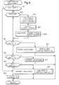
- Block 301 represents program instructions executed at the beginning of each period of vehicle operation for initializing various tables, timers, pointers etc. used in carrying out the control functions of the invention.
- instruction blocks 303-325 are repeatedly executed as designated by the flow diagram.
- Block 303 reads and conditions various input signals applied to the powertrain control unit 42 via lines 46-56.
- Block 305 performs various calibration table look-ups including the engine torque gain TQRAT and ITQ.
- TQRAT is determined as a function of the speed ratio across the torque converter (i.e. Nt/Ne).
- ITQ is determined as a function of Nt and is a signed variable meaning its contribution to the shift torque may be in either direction.
- Block 307 next calculates engine torque ETQ and shift torque TQ as previously described.
- Block 309 determines the desired ratio, Rdes, in a conventional manner such as by vehicle speed versus throttle position tables. In transmission control, this is commonly referred to as shift pattern generation. If the actual ratio Ract is equal to Rdes, as determined at block 311, block 313 is executed to determine the desired line pressure LPdes for steady state operation of the vehicle. If Ract is not equal to Rdes, shifting is indicated and block 315 is executed to determine the appropriate engine torque reduction as described in detail with reference to figure 4. Blocks 317-321 are next executed to determine the desired line pressure LPdes in accordance with the shift torque STQ immediately prior to shift initiation for shifting as well as the timing of the required solenoid state changes. In any case, block 323 is then executed to convert the desired line pressure LPdes to a solenoid duty cycles LP(DC), and to output the duty cycle and discrete solenoid states to the shift valves on lines 57 as conventionally practiced in the art.
- block 313 is executed to determine the desired line pressure LPdes for steady state operation of the vehicle.
- Block 325 is finally executed to develop a spark retard signals on line 40 for EST unit 38 for engine torque management and shift timing control during shifting. This may be accomplished for example by referencing a calibration table of percent engine torque reduction versus spark retard signal and outputting the spark retard signal on line 40.
- a preferred shift torque management flow diagram generally referred to in the main loop instruction block 315 of figure 3 is set forth in detailed steps 401-423.
- the following description is given with respect to a ratio change from one ratio to a lower ratio (upshift); however, it is to be understood that the method embodied in the flow diagram is applicable to downshifts as well with appropriate modification of the various variables, parameters and operations detailed below.
- decision block 401 is first encountered whereat a determination is made as to whether the ratio change has begun. As earlier described, the actual ratio Nt/No as represented in Ract is compared to a threshold value related to the first ratio RAT(x).
- a calibrated constant KRAT(x) such as 90% of the ratio RAT(x) provides a threshold through which as the ratio change progresses invokes steps 403-423 for engine torque reduction. Until Ract reaches the value KRAT(x), engine torque reduction steps are bypassed and block 423 is executed to set an engine torque reduction term ETQRED to zero.
- Step 405 stores various quantities into torque management working variables (TMx).
- TMx torque management shift torque
- TMSTQ torque management shift torque
- ETQ and TQRAT are saved in torque management values TMETQ and TMTQRAT, respectively.
- Block 407 performs a look-up from a calibration table of a predetermined target shift torque reduction (STQRED) as a function of the shift torque present at the initiation of the ratio change.
- STQRED preferably is in the form of a percentage of the shift torque; however, STQRED alternatively may be in the form of a torque value.
- Block 409 now performs the critical steps of accounting for the proportional constituents of the shift torque in calculating the percent engine torque reduction.
- the calculation is set up to return a maximum engine torque reduction expressed as a percent of engine torque (MAXETQRED). This may be accomplished in a couple alternative ways depending upon the form that STQRED takes (i.e. percent of shift torque or torque value).
- STQRED is expressed as a percent of shift torque
- STQRED is multiplied by the ratio of total shift torque (TMSTQ) to input torque (TMETQ*TMTQRAT).
- TMSTQ total shift torque
- TMETQ*TMTQRAT input torque
- Blocks 411-423 are next executed after block 409 establishes MAXETQRED and in all subsequent passes through the present flow diagram for the present ratio change by virtue of a negative response at block 403.
- This portion of the flow diagram effectuate the ramp in and ramp out of the engine torque reduction as previously discussed.
- Blocks 415-417 maintain the engine torque reduction at the maximum engine torque reduction during the portions of the ratio change therebetween.
- Block 411 determines if Ract is within a range of ratio progression appropriate for continued ramping and if so executes block 413.
- the range in the present embodiment is bounded by the calibrated constant KRAT(x) previously described and a calibrated constant KRAT(x+a) corresponding to a ratio forward of KRAT(x) in the shift progression .
- Block 413 establishes the engine torque reduction ETQRED in proportion to the ratio change progression through the range KRAT(x) to KRAT(x+a) by multiplication of MAXETQRED with a fractional completion term shown in brackets.
- the completion term progresses from zero to one as the Ract progresses from KRAT(x) to KRAT(x+a). Thereafter Ract reaching KRAT(x+a), block 411 is answered negatively and processing passes to block 415.
- Block 415 determines if Ract is within a range of ratio progression appropriate for full application of the maximum engine torque reduction MAXETQRED and if so executes block 417.
- the range in the present embodiment is bounded by the calibrated constant KRAT(x+a) previously described and a calibrated constant KRAT(y-b) corresponding to a ratio prior to the end of the shift at which ramping out of the engine torque reduction is appropriate.
- Block 417 establishes the engine torque reduction ETQRED as MAXETQRED through the range KRAT(x+a) to KRAT(x-b). Thereafter Ract reaching KRAT(x-b), block 415 is answered negatively and processing passes to block 419.
- Block 419 determines if Ract is within a range of ratio progression appropriate for ramping out of the engine torque reduction and if so executes block 421.
- the range in the present embodiment is bounded by the calibrated constant KRAT(y-b) previously described and a calibrated constant KRAT(y) such as 110% of the ratio RAT(y).
- Block 421 establishes the engine torque reduction ETQRED in proportion to the ratio change progression through the range KRAT(y-b) to KRAT(y) by multiplication of MAXETQRED with a fractional completion term shown in brackets that progresses from one to zero as the Ract progresses from KRAT(y-b) to KRAT(y). Thereafter Ract reaching KRAT(y), block 419 is answered negatively and processing passes to block 423 whereat the engine torque reduction is set to zero for the remainder of the shift.
Landscapes
- Engineering & Computer Science (AREA)
- Chemical & Material Sciences (AREA)
- Combustion & Propulsion (AREA)
- Mechanical Engineering (AREA)
- Transportation (AREA)
- Automation & Control Theory (AREA)
- General Engineering & Computer Science (AREA)
- Control Of Transmission Device (AREA)
Applications Claiming Priority (2)
| Application Number | Priority Date | Filing Date | Title |
|---|---|---|---|
| US497167 | 1974-08-12 | ||
| US08/497,167 US5562567A (en) | 1995-06-30 | 1995-06-30 | Shift torque management |
Publications (2)
| Publication Number | Publication Date |
|---|---|
| EP0751028A2 true EP0751028A2 (de) | 1997-01-02 |
| EP0751028A3 EP0751028A3 (de) | 1998-04-01 |
Family
ID=23975736
Family Applications (1)
| Application Number | Title | Priority Date | Filing Date |
|---|---|---|---|
| EP96201473A Withdrawn EP0751028A3 (de) | 1995-06-30 | 1996-05-28 | Schaltdrehmomentsteuerung |
Country Status (2)
| Country | Link |
|---|---|
| US (1) | US5562567A (de) |
| EP (1) | EP0751028A3 (de) |
Cited By (2)
| Publication number | Priority date | Publication date | Assignee | Title |
|---|---|---|---|---|
| EP1431622A4 (de) * | 2001-09-28 | 2007-07-04 | Jatco Ltd | Gangschaltdrehmomentverminderungssteuerungs-vorrichtung für automatisches getriebe |
| CN103423432B (zh) * | 2012-05-15 | 2017-04-12 | 宝马股份公司 | 用于实施降挡过程的方法 |
Families Citing this family (11)
| Publication number | Priority date | Publication date | Assignee | Title |
|---|---|---|---|---|
| KR100298250B1 (ko) * | 1992-09-16 | 2001-10-24 | 가나이 쓰도무 | 차량용구동력제어장치 |
| US5984830A (en) * | 1997-07-03 | 1999-11-16 | Caterpillar Inc. | Apparatus and method for shifting into a lower gear of a manual transmission |
| DE19856320A1 (de) | 1998-12-07 | 2000-06-08 | Zahnradfabrik Friedrichshafen | Verfahren zum Steuern eines Automatgetriebes |
| US6254509B1 (en) * | 1999-11-29 | 2001-07-03 | Deere & Company | Engine throttle control for improved shifting |
| US6520889B1 (en) * | 2000-11-01 | 2003-02-18 | Eaton Corporation | Adaptive engine control for shifting to neutral |
| JP3872783B2 (ja) * | 2003-09-03 | 2007-01-24 | 日産自動車株式会社 | 自動変速機の変速ショック軽減装置 |
| US8011274B2 (en) * | 2006-08-28 | 2011-09-06 | Vladimir Abramov | Gear box apparatus |
| US7349754B1 (en) * | 2006-09-05 | 2008-03-25 | Ford Global Technologies, Llc | Providing component-specific performance characterization data for an assembly or subsystem |
| KR20080023038A (ko) * | 2006-09-08 | 2008-03-12 | 현대자동차주식회사 | 자동변속기의 스킵 다운 변속 제어방법 |
| US9523341B2 (en) | 2014-09-04 | 2016-12-20 | Ford Global Technologies, Llc | Methods and system for improving hybrid transmission gear shifting |
| US12187305B2 (en) | 2022-06-08 | 2025-01-07 | Ford Global Technologies, Llc | Powertrain torque control during shift to four-wheel drive in automated-driving mode |
Family Cites Families (12)
| Publication number | Priority date | Publication date | Assignee | Title |
|---|---|---|---|---|
| DE59005971D1 (de) * | 1990-03-06 | 1994-07-07 | Siemens Ag | Steuerung für einen kraftfahrzeugantrieb. |
| JP2949156B2 (ja) * | 1990-03-26 | 1999-09-13 | トヨタ自動車株式会社 | 自動変速機のダウンシフト制御装置 |
| JPH03292446A (ja) * | 1990-04-06 | 1991-12-24 | Japan Electron Control Syst Co Ltd | 自動変速機の変速作動油圧制御装置 |
| JP2600982B2 (ja) * | 1990-06-08 | 1997-04-16 | 日産自動車株式会社 | 自動変速機とエンジンの総合制御システム |
| DE4037092A1 (de) * | 1990-11-22 | 1992-05-27 | Zahnradfabrik Friedrichshafen | Verfahren zur steuerung des drehmoments einer brennkraftmaschine |
| US5295415A (en) * | 1991-03-29 | 1994-03-22 | Mazda Motor Corporation | Torque control apparatus for engine and automatic transmission |
| US5305213A (en) * | 1991-05-09 | 1994-04-19 | Eaton Corporation | Driveline torque limit control strategy-using SAE J1922 type engine control |
| JP3312918B2 (ja) * | 1991-10-09 | 2002-08-12 | マツダ株式会社 | エンジン及び自動変速機の制御装置 |
| JPH0672187A (ja) * | 1992-05-28 | 1994-03-15 | Mitsubishi Electric Corp | 自動変速機付車両用エンジン制御装置及びその制御方法 |
| KR100298250B1 (ko) * | 1992-09-16 | 2001-10-24 | 가나이 쓰도무 | 차량용구동력제어장치 |
| JP3445291B2 (ja) * | 1992-10-13 | 2003-09-08 | 株式会社日立製作所 | 駆動トルク制御装置 |
| US5608626A (en) * | 1993-03-26 | 1997-03-04 | Hitachi, Ltd. | Drive shaft torque controlling apparatus for use in a vehicle having a power transmission mechanism and method therefor |
-
1995
- 1995-06-30 US US08/497,167 patent/US5562567A/en not_active Expired - Lifetime
-
1996
- 1996-05-28 EP EP96201473A patent/EP0751028A3/de not_active Withdrawn
Cited By (2)
| Publication number | Priority date | Publication date | Assignee | Title |
|---|---|---|---|---|
| EP1431622A4 (de) * | 2001-09-28 | 2007-07-04 | Jatco Ltd | Gangschaltdrehmomentverminderungssteuerungs-vorrichtung für automatisches getriebe |
| CN103423432B (zh) * | 2012-05-15 | 2017-04-12 | 宝马股份公司 | 用于实施降挡过程的方法 |
Also Published As
| Publication number | Publication date |
|---|---|
| EP0751028A3 (de) | 1998-04-01 |
| US5562567A (en) | 1996-10-08 |
Similar Documents
| Publication | Publication Date | Title |
|---|---|---|
| US7393305B2 (en) | Controller for automatic transmission | |
| KR100298250B1 (ko) | 차량용구동력제어장치 | |
| US6701246B2 (en) | Engine torque determination for powertrain with torque converter | |
| US5188005A (en) | Method and system for improving smoothness of shifts in an automatic transmission | |
| EP1586885B1 (de) | Fahrzeugeschwindigkeits-Regelungssystem für einen Fahrzeugprüfstand mit Dynamometer | |
| US5282401A (en) | Adaptive electronic control of power-on upshifting in an automatic transmission | |
| US5785627A (en) | Torque feedback shift control device and method | |
| US5562567A (en) | Shift torque management | |
| EP2105634B1 (de) | Automatische Übertragungssteuerung und automatisches Übertragungssteuerungsverfahren | |
| EP0751323B1 (de) | Hochtemperaturmodus für Automatikgetriebe | |
| US5201250A (en) | Fuel cut-off inhibit for a power-off upshift | |
| US7314428B2 (en) | Downshift control for automotive automatic transmission | |
| US5484353A (en) | Method for reducing driveline disturbances by controlling torque converter clutch application | |
| EP0649999B1 (de) | Steuerung einer Drehmomentwandler-Überbrückungskupplung eines automatischen Getriebes | |
| EP0512596B1 (de) | Verfahren zum Regeln der Gangänderungskennlinien für das automatische Getriebe eines Kraftfahrzeuges | |
| EP0647802B1 (de) | Steuerung der Gangwechsel in einem automatischen Getriebe | |
| CA1303189C (en) | Performance control of a motor vehicle engine for consistent high quality transmission shifting | |
| US5720696A (en) | Method of shift control using moment of inertia estimation | |
| JP3312918B2 (ja) | エンジン及び自動変速機の制御装置 | |
| JP3323976B2 (ja) | 変速ショック低減装置 | |
| US5050082A (en) | System for controlling automotive automatic transmission | |
| JPH05248528A (ja) | 自動変速機の変速制御装置 | |
| JP3430275B2 (ja) | 自動変速機の変速終了時点判別装置およびそれを用いたパワートレーンの変速ショック軽減用総合制御装置 | |
| JPH0727211A (ja) | 自動変速機の変速制御装置 | |
| JP2000118267A (ja) | 車速制御装置 |
Legal Events
| Date | Code | Title | Description |
|---|---|---|---|
| PUAI | Public reference made under article 153(3) epc to a published international application that has entered the european phase |
Free format text: ORIGINAL CODE: 0009012 |
|
| AK | Designated contracting states |
Kind code of ref document: A2 Designated state(s): DE FR GB IT |
|
| PUAL | Search report despatched |
Free format text: ORIGINAL CODE: 0009013 |
|
| AK | Designated contracting states |
Kind code of ref document: A3 Designated state(s): DE FR GB IT |
|
| 17P | Request for examination filed |
Effective date: 19981001 |
|
| 17Q | First examination report despatched |
Effective date: 19990713 |
|
| STAA | Information on the status of an ep patent application or granted ep patent |
Free format text: STATUS: THE APPLICATION IS DEEMED TO BE WITHDRAWN |
|
| 18D | Application deemed to be withdrawn |
Effective date: 20010116 |